iPhone 4 Tutorial: Replace Standby Sensor Cable
Duration: 75 min.
Steps: 39 Steps
Welcome to your go-to guide for swapping out the standby/sensor cable on your iPhone 4! If your standby button has gone on strike or feels like a soggy noodle, this repair is just what the doctor ordered. Even if your screen refuses to dim during phone calls or your microphone is playing hard to get during videos or FaceTime, fear not! Replacing this cable will get things back to normal. Let’s dive into the steps and get your iPhone back in action!
Step 1

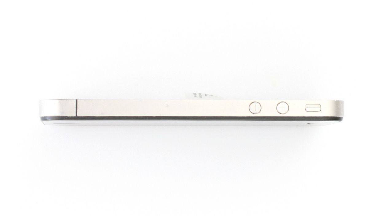
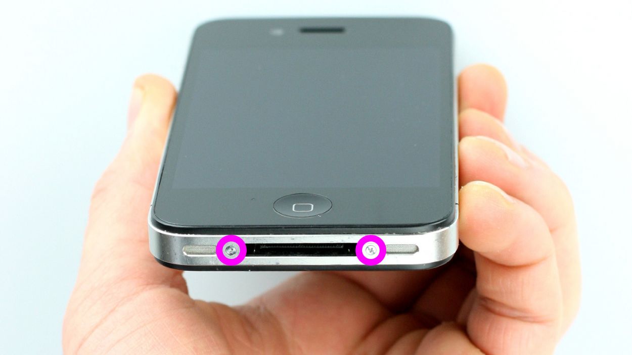
– Depending on your iPhone’s birthdate, you’ll want to grab either a Phillips screwdriver or a pentalobe screwdriver to get that phone open and ready for action!
– These little screws are hanging out to the right and left of the dock connector, just waiting for you. Make sure to keep them cozy in the same compartment of your organizer tray. You’ll need 2 x 3.6 mm pentalobe/Phillips screws for this step!
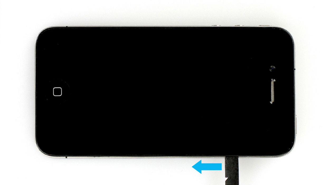
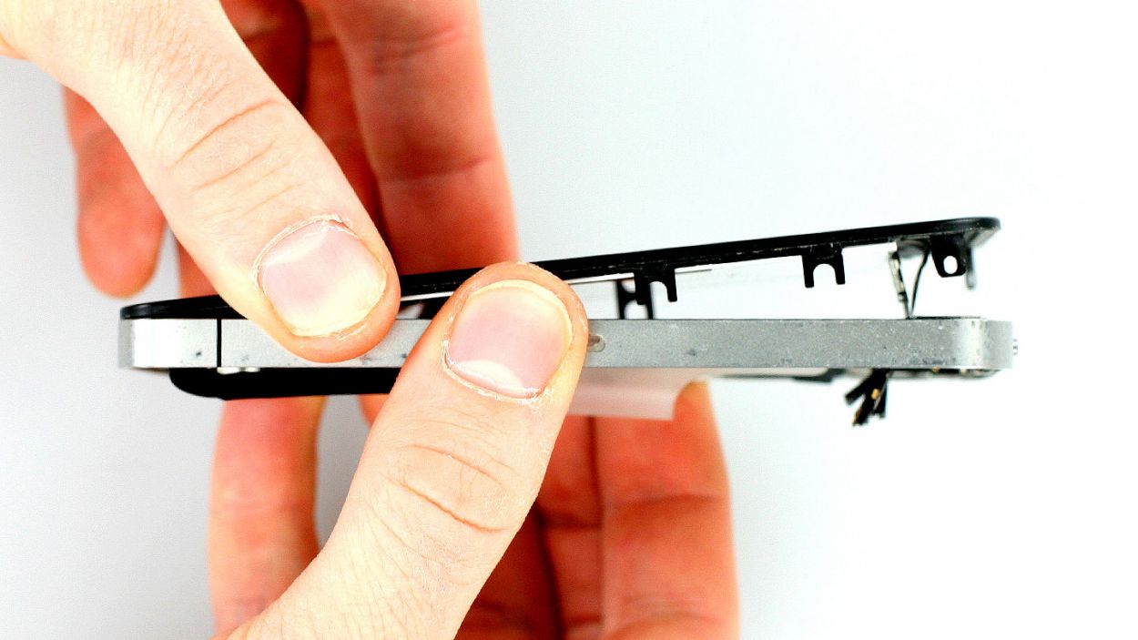
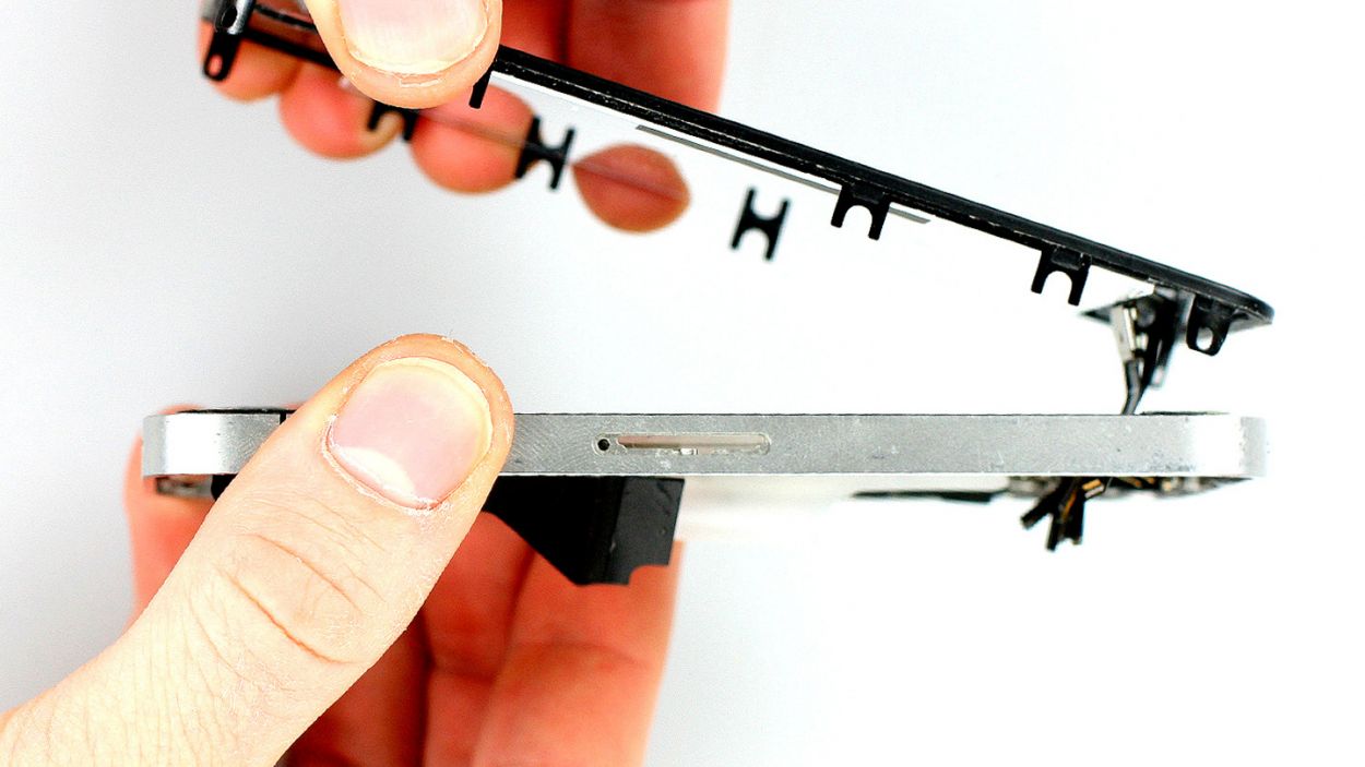
Step 2

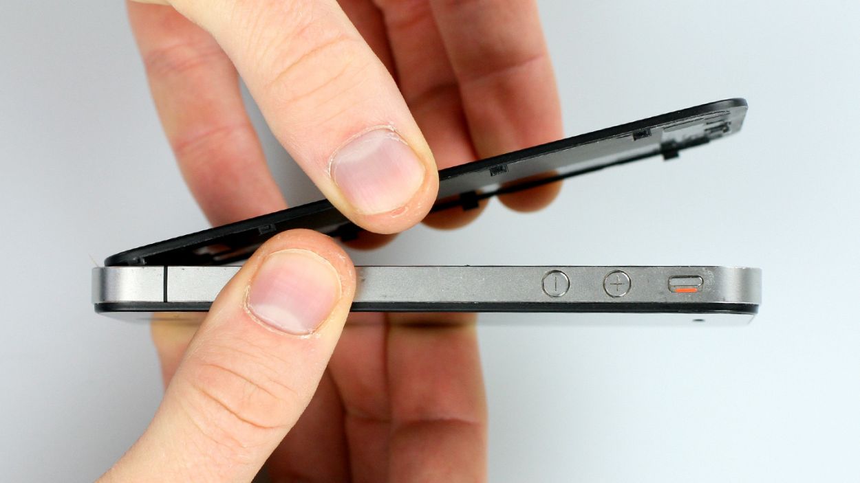
– Give your iPhone’s back cover a gentle nudge with your thumbs or the palm of your hand, pushing it about 4 mm away from the bottom where the dock connector is hanging out (check out figure 1).
– Once you’ve done that, feel free to lift the back cover from the end that’s now peeking out past the phone (see figure 2).
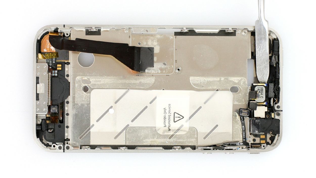
Step 3

Heads up! The battery contact point on the logic board might decide to take a little vacation. If it breaks off but the soldering points are still hanging in there, you can just solder it back on like a pro!
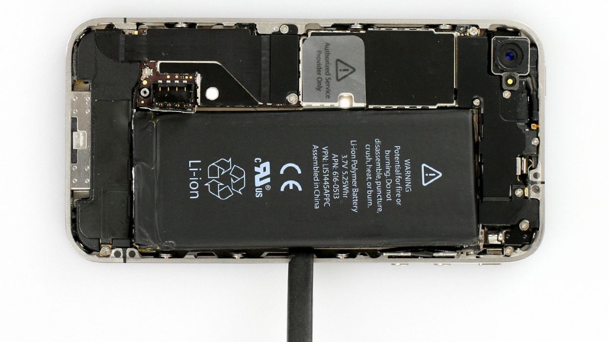
– If your iPhone is still awake, it’s time to send it to sleep! Just hold down the standby button for about five seconds and follow the friendly prompt that pops up on your screen.
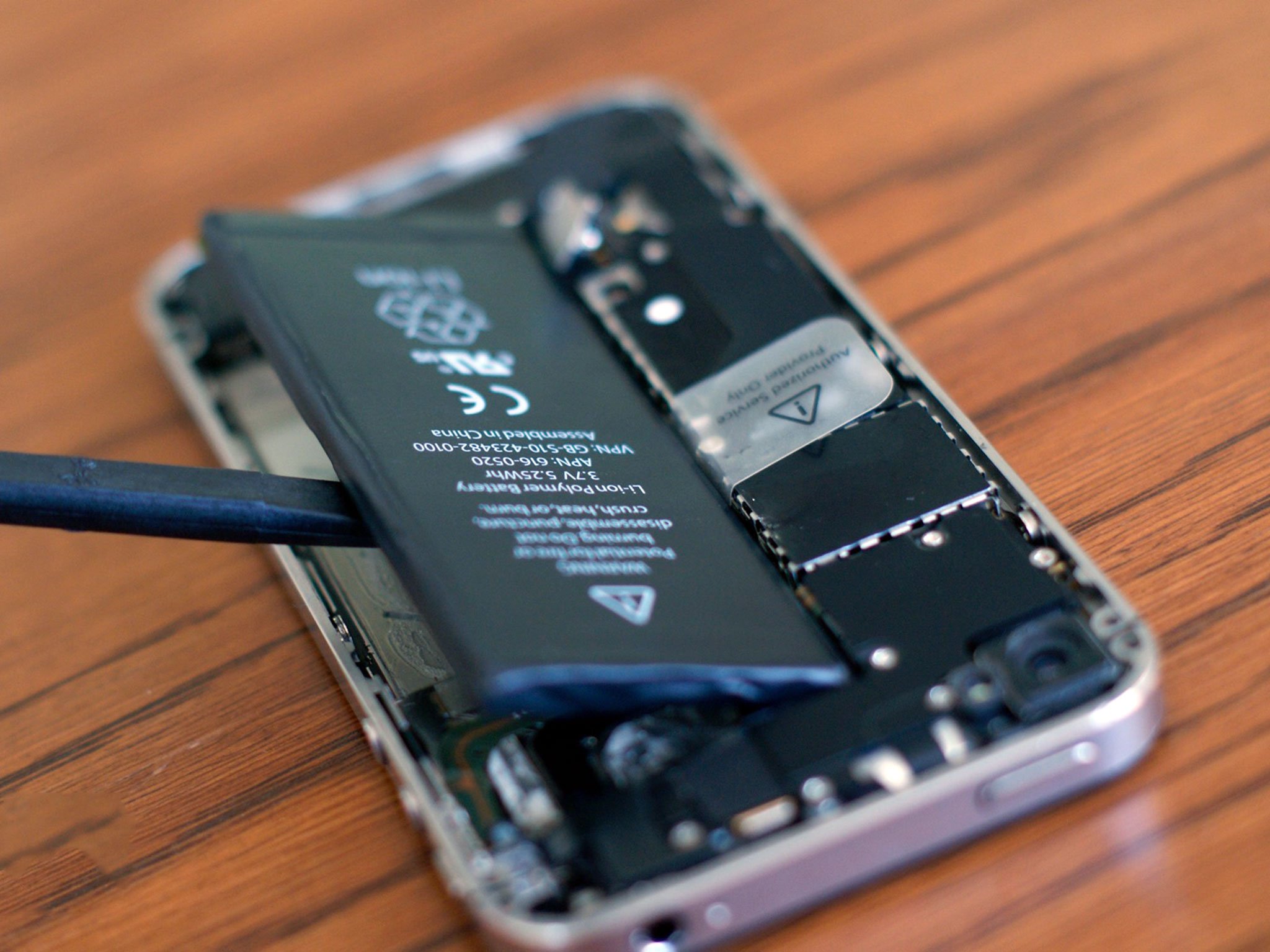
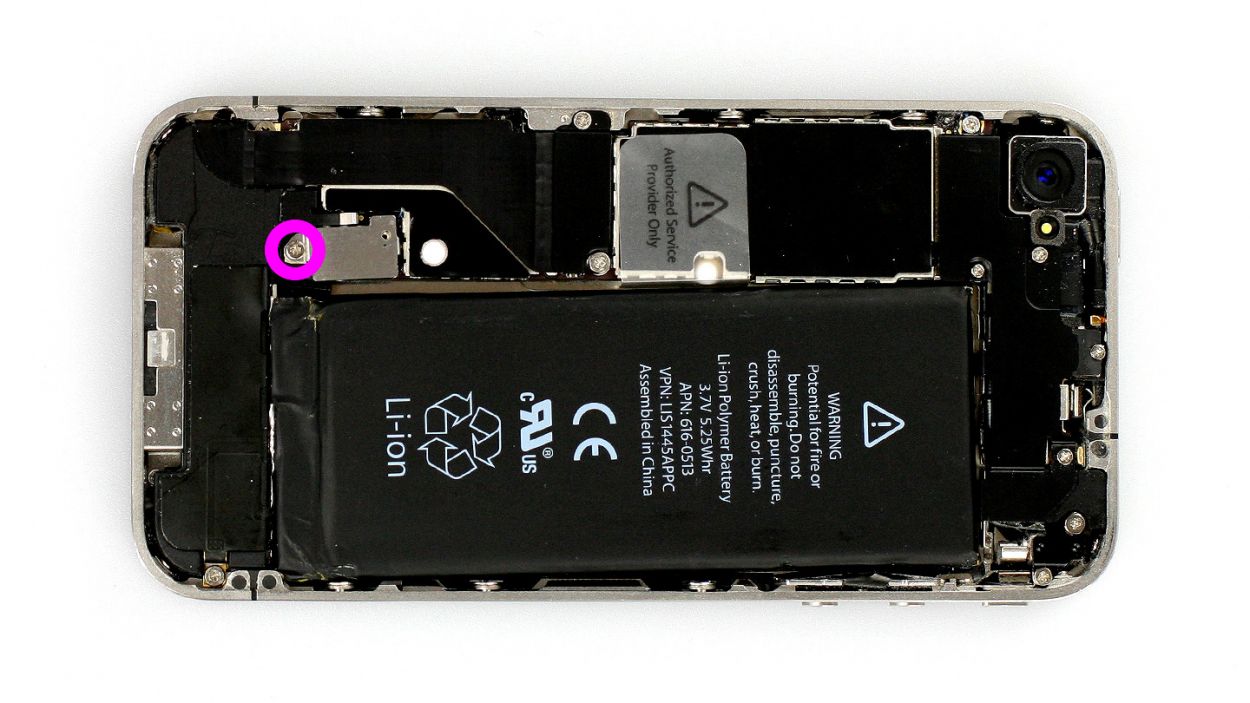
– Next up, grab your trusty Phillips screwdriver and remove the screw from the battery connector (check out figure 1 for a visual). Make sure to keep that little screw safe in a cozy compartment of your organizer tray. Remember, it’s a 1 x 2.6 mm Phillips screw. Just a heads up: the battery contact point on the logic board might decide to take a little vacation. If it does break off but the soldering points are still holding strong, you can totally solder it back on yourself!
– Now, let’s gently lift off the battery connector. Use the pointed ESD spudger and slide it in just below the silver cover plate (figure 2 will guide you). No spudger? No worries! Your fingernail can step in as a backup.
– For the rest of this repair adventure, you can also opt for a metal laboratory spatula instead of the spudger if that suits you better. It might make some steps a breeze! However, we still think the ESD spudger is the star of the show for precision electronics.
Step 4

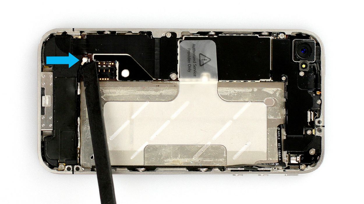
– The antenna cover is hiding under the battery connector. Pop it off and place it in the same cozy spot in your organizer tray as that Phillips screw you just liberated (check out figure 1 for a visual!).
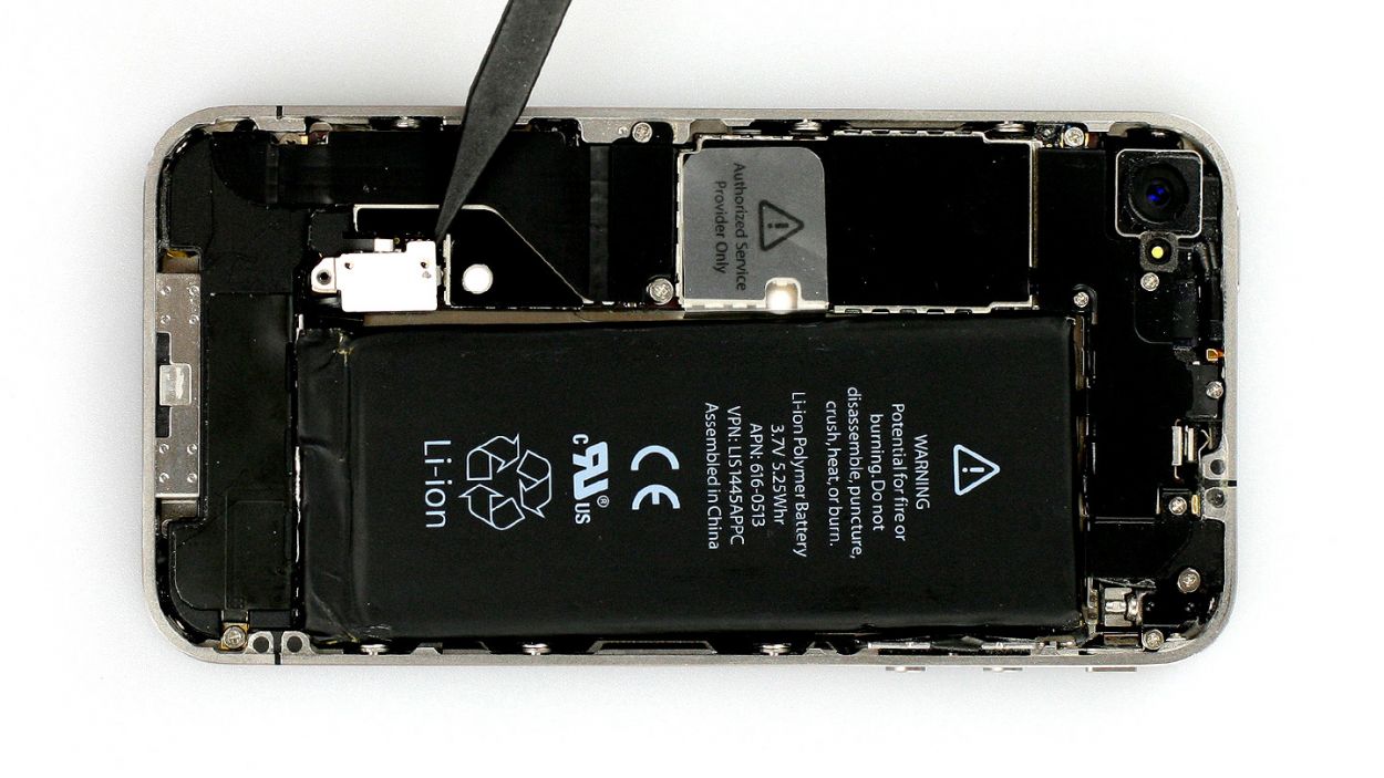
– Now, let’s tackle that battery! It might be glued down tighter than a stubborn lid on a jar. Gently slide the flat end of the spudger into the gap (about 1 cm to the left of the volume down button) between the battery and the outer frame, and slowly lift it out (see figure 2). If it’s really putting up a fight, try prying it off from other leverage points to the right and left. And if all else fails, a little warmth from a heat gun can help soften that glue!
– And while you’re at it, don’t forget to disconnect the antenna connector. Just give it a gentle tug with the spudger to pull it off the plug head (see figure 3).
Step 5
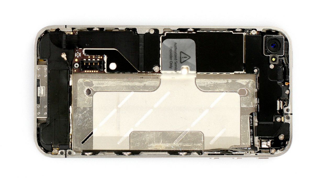
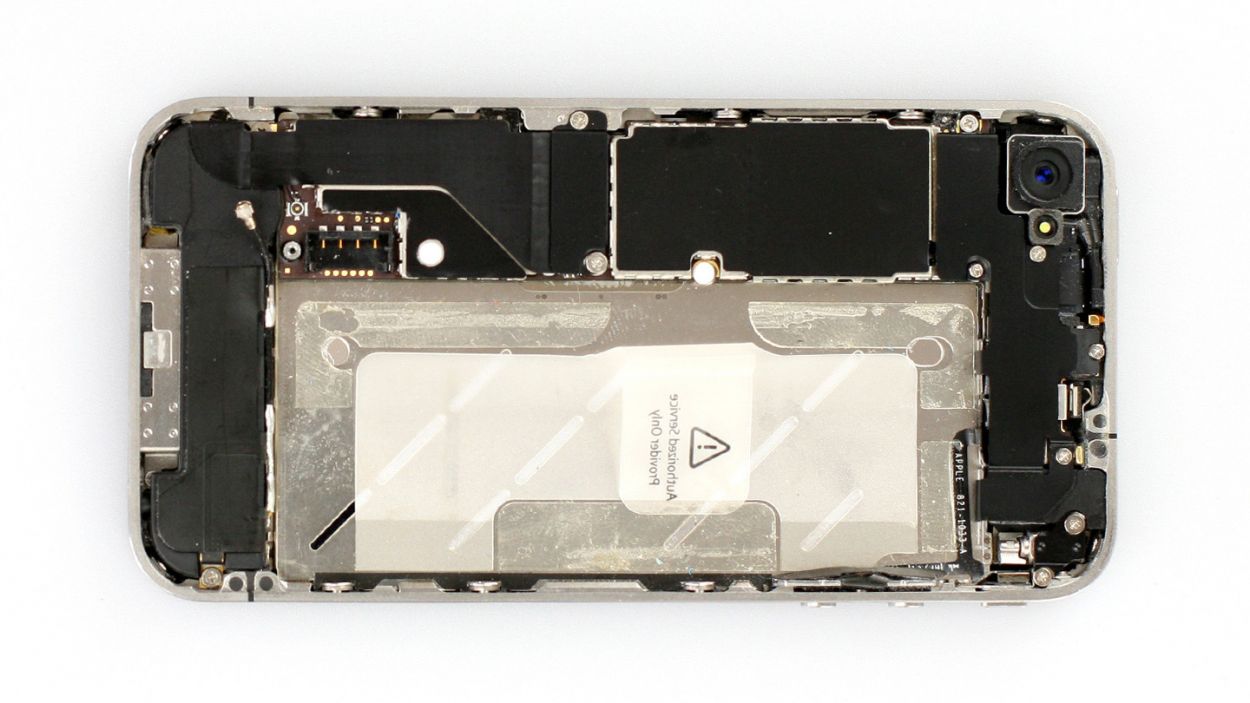
– Fold that cheeky plastic tab with the warning over and give it a good press onto the lower adhesive strip. This way, it won’t be a pesky distraction while you’re working your repair magic!
– Of course, if you’re feeling a bit rebellious, you can totally just ditch the plastic tab.
Step 6

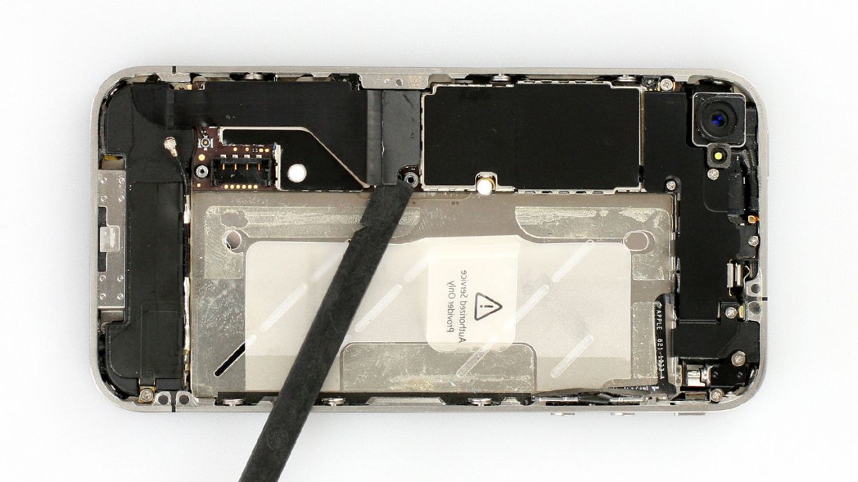
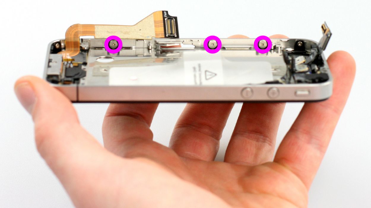
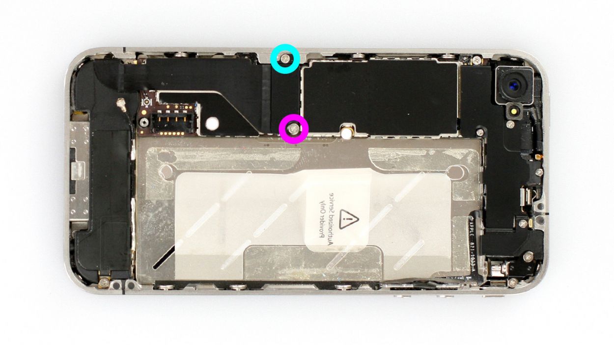
– First, let’s take out those two Phillips screws from the dock connection cable, and then remove the black (or silver if you’ve got a newer model) cover (check out figure 1 for a visual!). You’ll need 1 x 1.6 mm Phillips screw and 1 x 1.2 mm Phillips screw for this step!
– Make sure to keep those screws and the cover in the same cozy compartment of your organizer tray. Trust me, it’ll make things a lot easier later on!
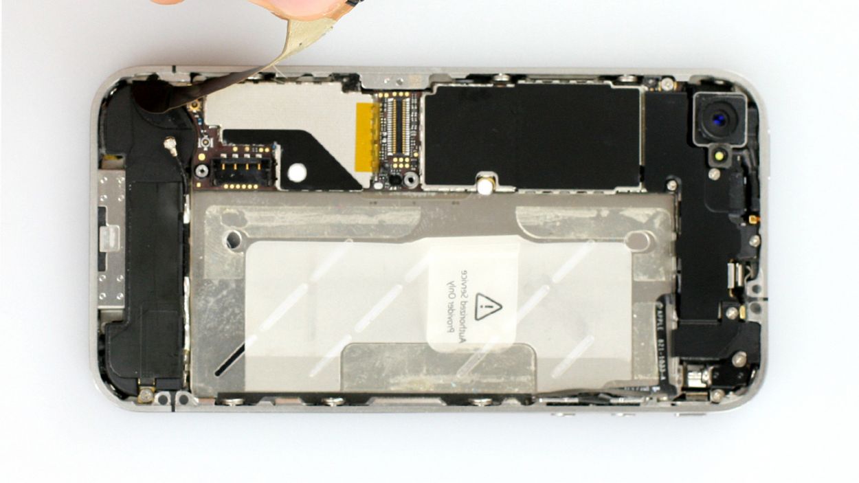
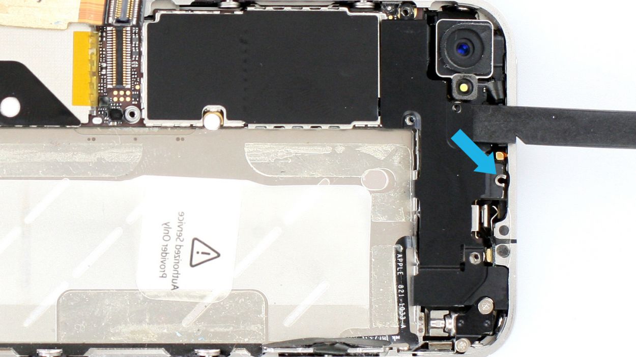
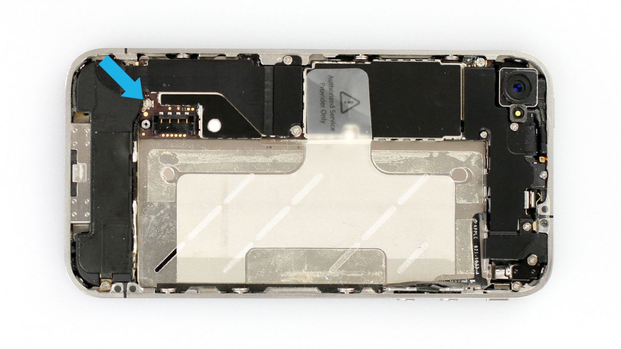
– Now it’s time to gently detach the connector. Grab your trusty spudger and use the flat end to lift it off. If you’re feeling a bit daring, your fingernail can do the trick too (see figure 2).
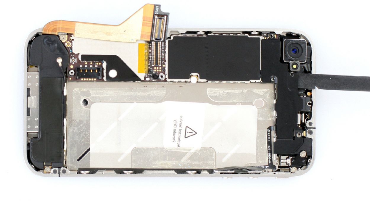
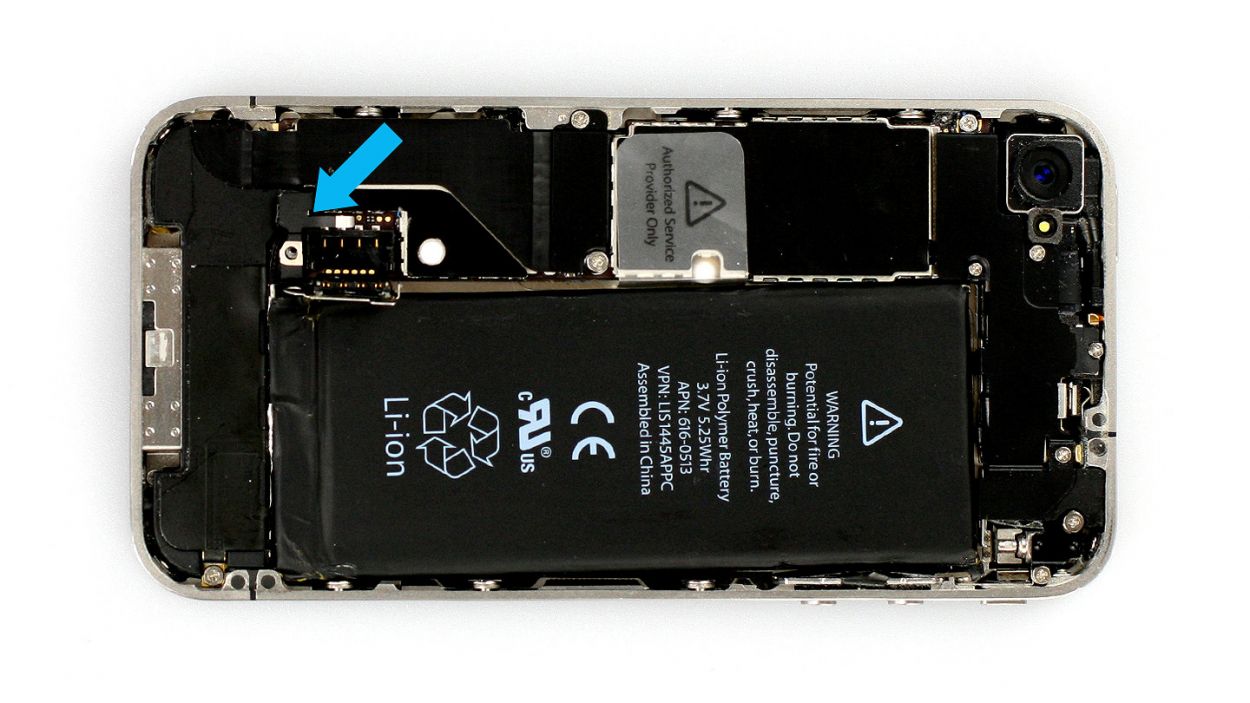
– Carefully pull the flat cable that’s lightly glued to the logic board and bend it gently over the frame (take a peek at figure 3 for guidance).
Step 7

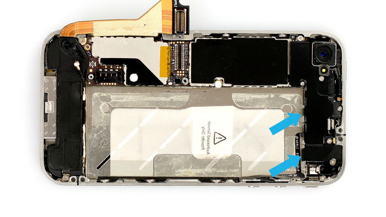
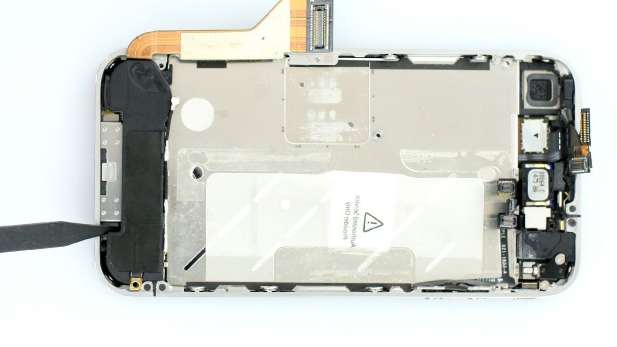
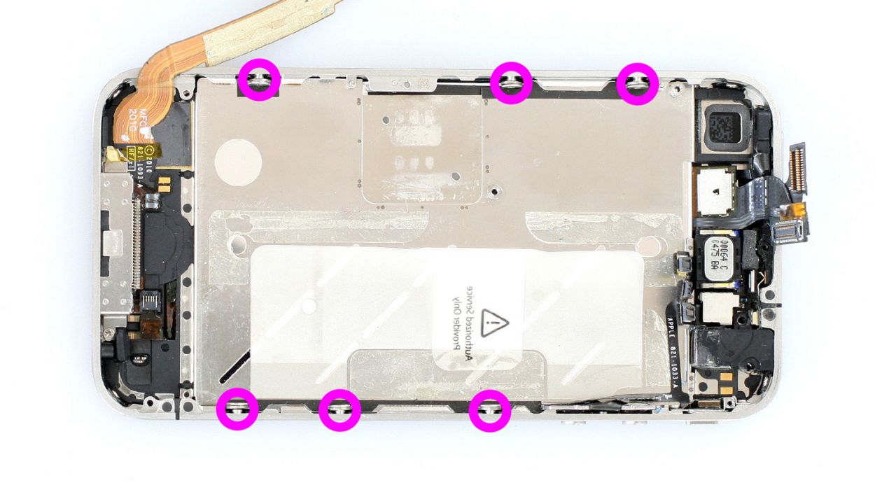
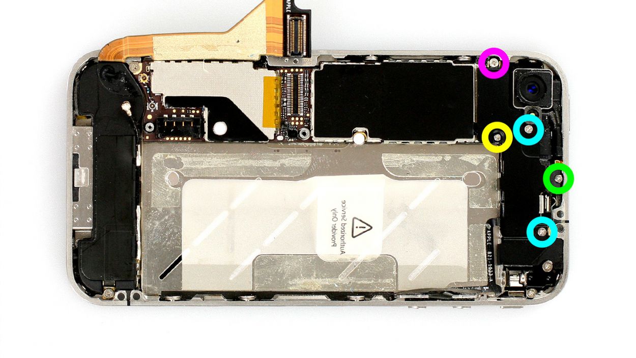
– Time to get those five Phillips screws out of hiding! Grab your trusty screwdriver and tackle them one by one. (Check out figure 1 for a little visual help!) You’ll need: 1 x 2.3 mm Phillips screw, 2 x 1.6 mm Phillips screws, 1 x 4.8 mm Phillips Wi-Fi screw, and 1 x 1.3 mm Phillips screw.
– Once you’ve got those screws out, it’s spudger time! Use the flat end to gently detach the cover. (Figure 2 is your guide here.)
– Now, lift that cover right out of the phone. Just a heads-up: it’s hooked on in two spots, so be a little gentle as you wiggle it free! (See figure 3 for a sneak peek.)
Step 8
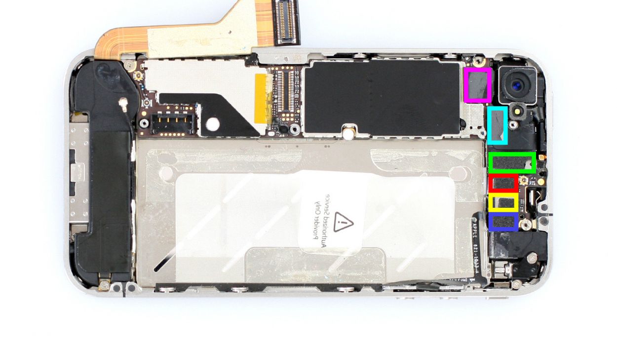
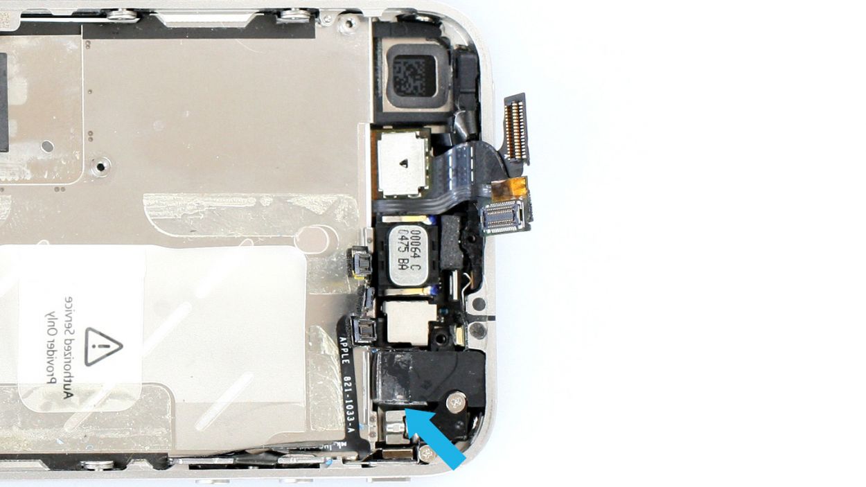
Be particularly careful with the headphone output connection. There’s a little resistor there that you need in order for the front camera to work.Don’t break it off (see figure 3).
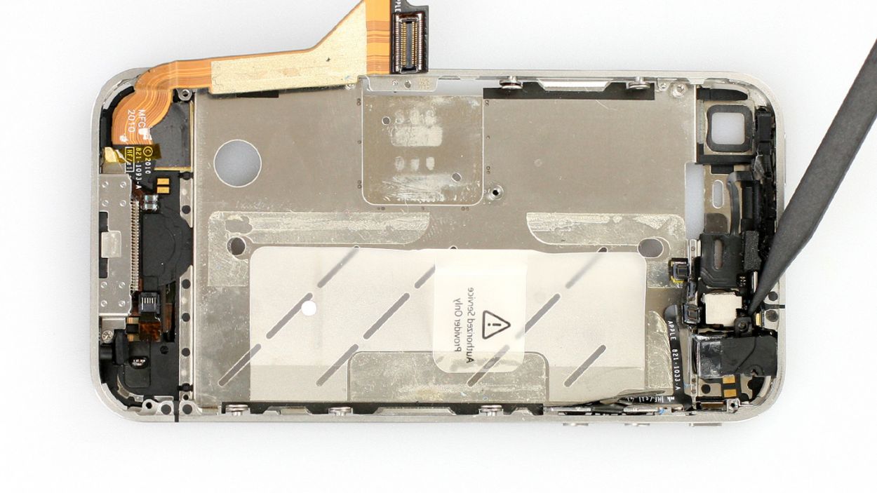
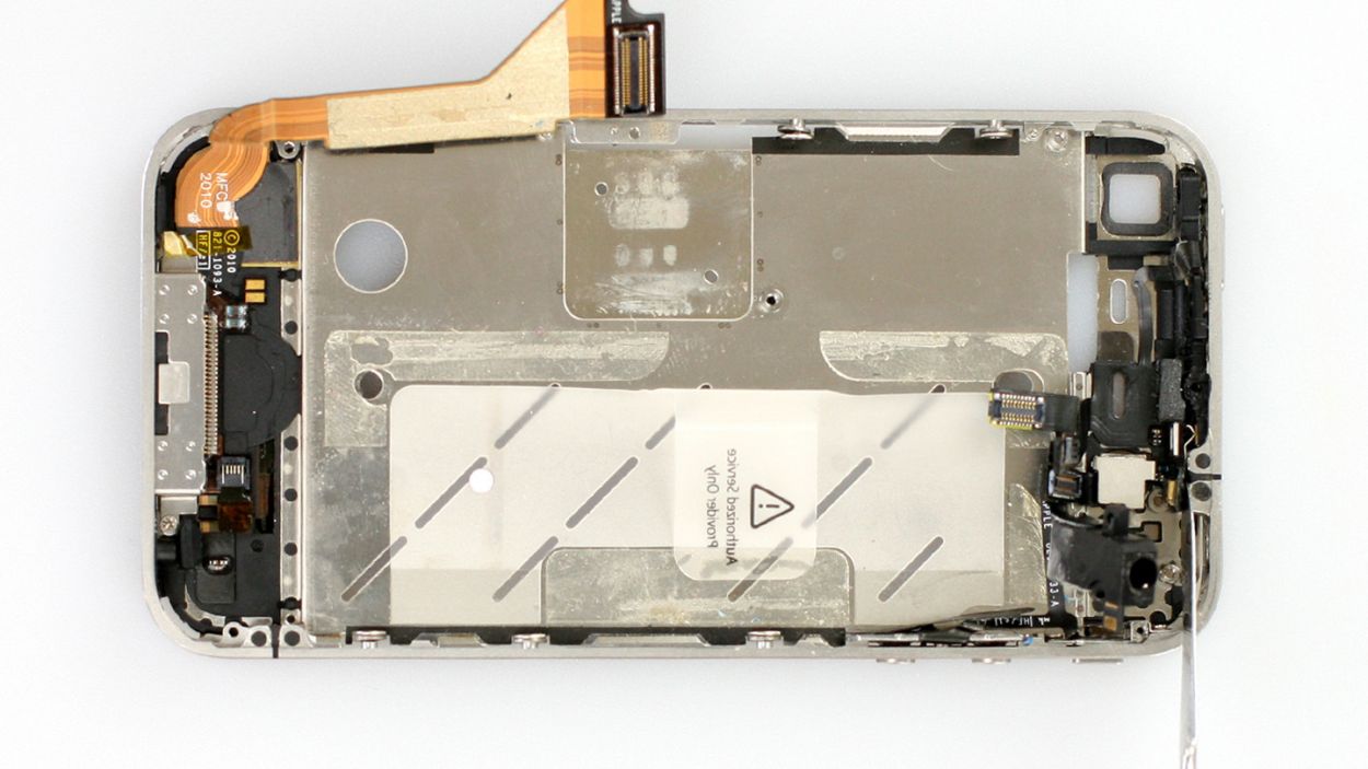
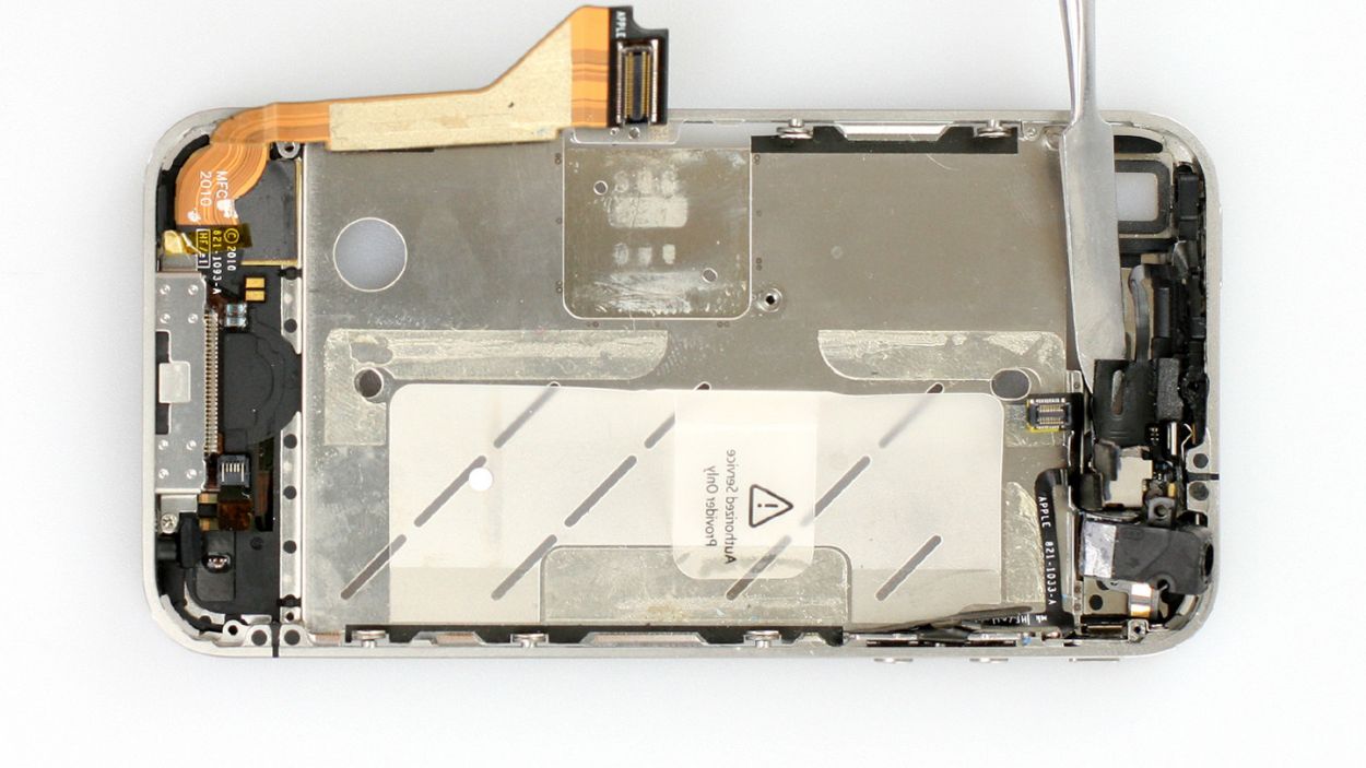
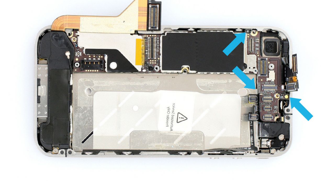
– Alright, it’s time to disconnect five connectors! But hey, let’s take it slow and steady, alright? (Check out figure 1 for a visual guide!) Here’s the lineup: Touchscreen, LCD, Front camera, Headphone output/volume controller, and the Standby/proximity sensor. Oh, and don’t forget the Camera, which we’ll tackle in the next step. Just a friendly reminder: be super gentle with that headphone output connection. There’s a tiny resistor that’s crucial for the front camera’s operation. We definitely don’t want that little guy to break off (see figure 3)!
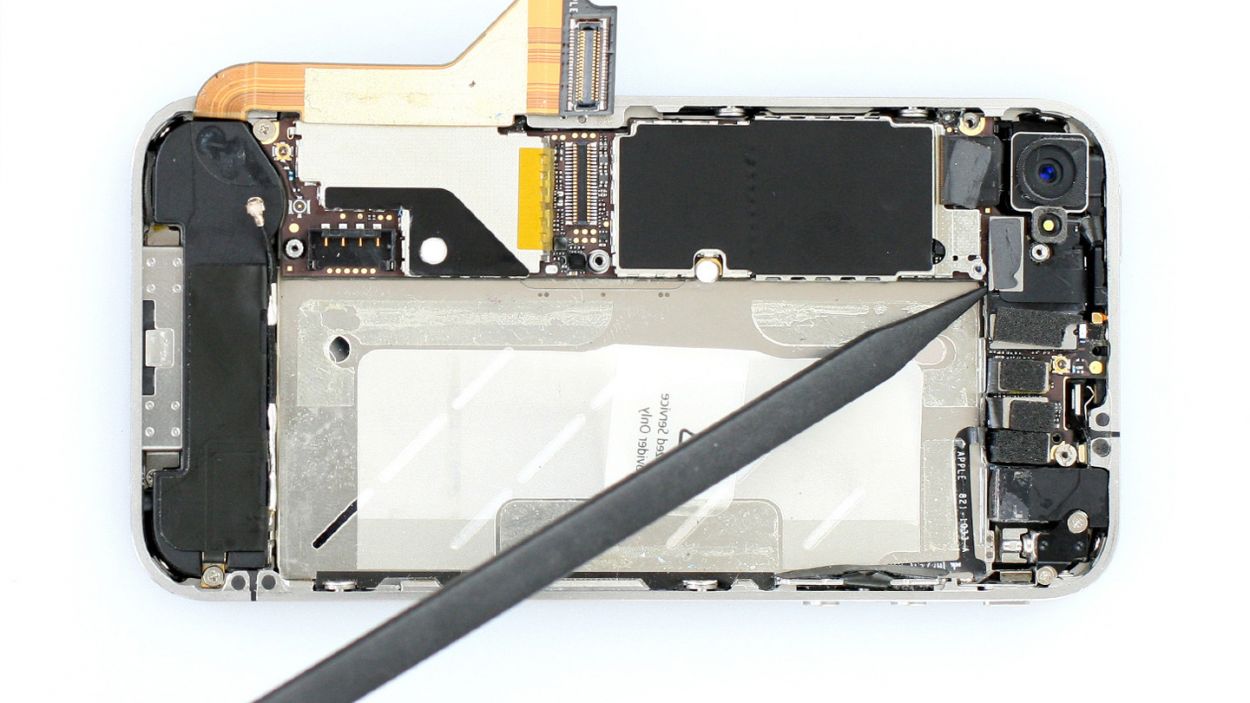
– Now, grab your trusty spudger and slide the pointed tip just below the contact, giving it a gentle lift (figure 2 will show you how). Remember to be cautious and avoid breaking off any resistors that are soldered onto the logic board. You’ve got this!
Step 9
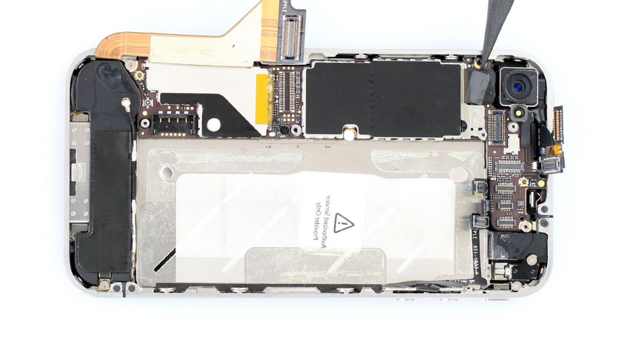
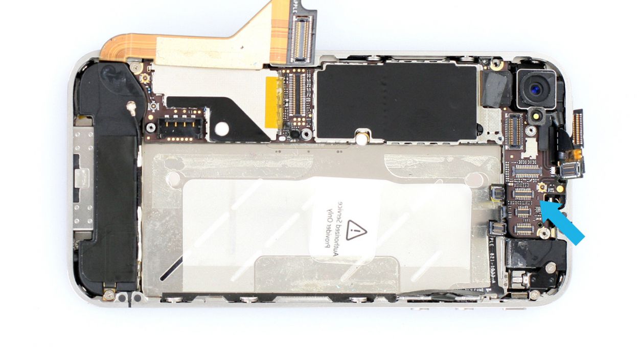
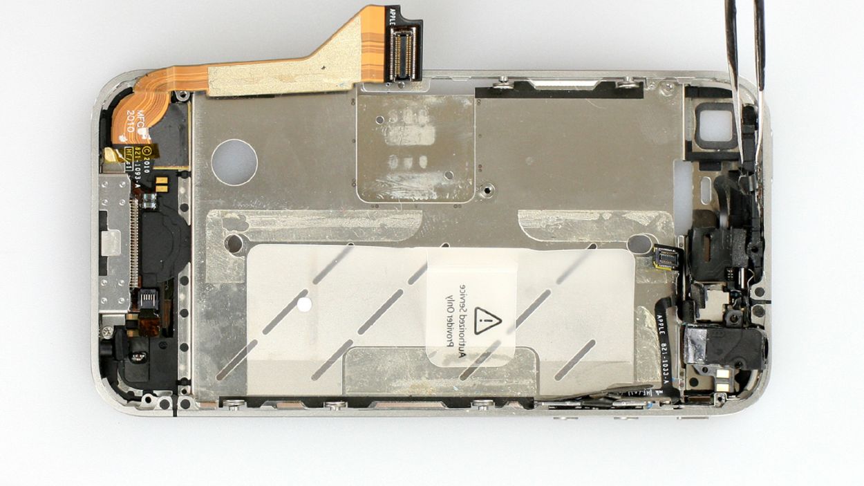
– Gently lift the camera connector just like you did with the other connectors, and then pop that camera out with ease!
Step 10

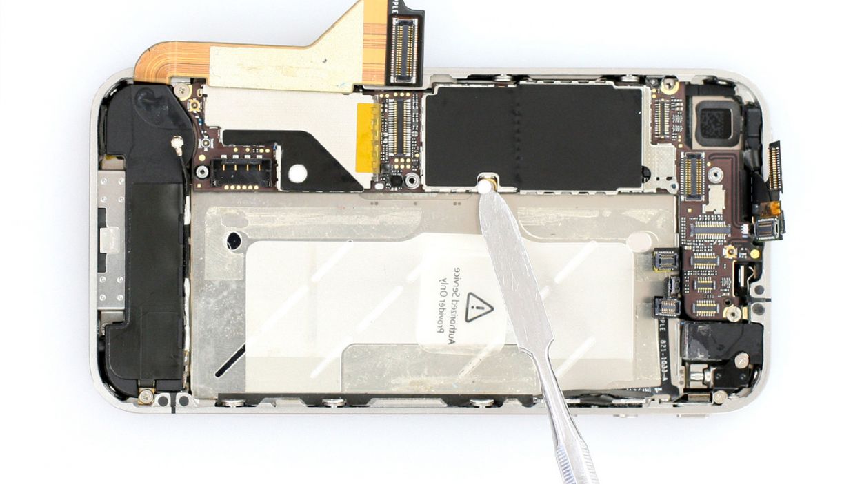
– Peel off that sneaky white water indicator sticker! Grab your tweezers or a lab spatula to help out. If it’s playing hard to get, a little hot air can work wonders.
– Underneath, you’ll find a Phillips screw waiting for you.
– To keep things tidy, stick that sticker on the plastic tab so it doesn’t wander off.
Step 11
– Grab your trusty SIM Tool or a simple paperclip to pop that SIM card tray out. Just press the SIM Tool into the tiny hole on the tray, and voilà, it’s out!
Step 12

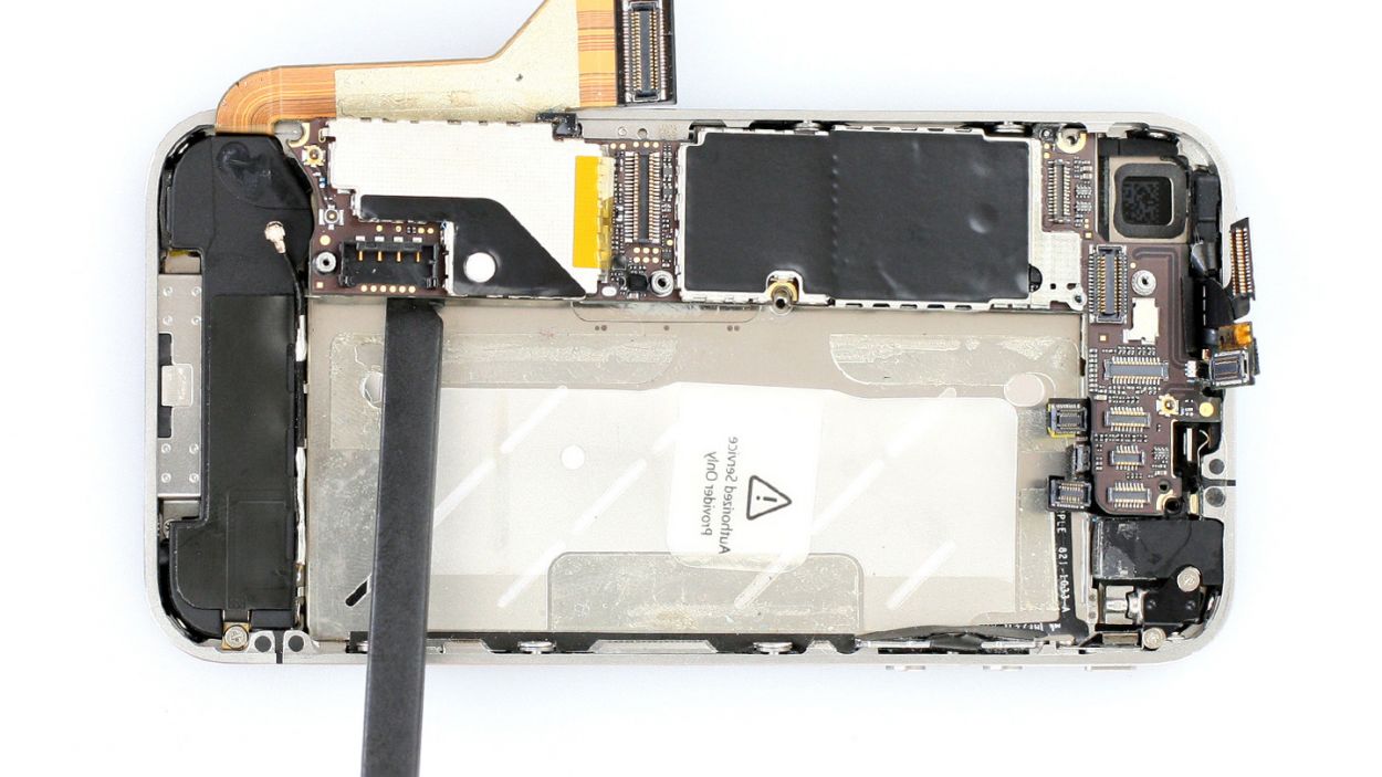

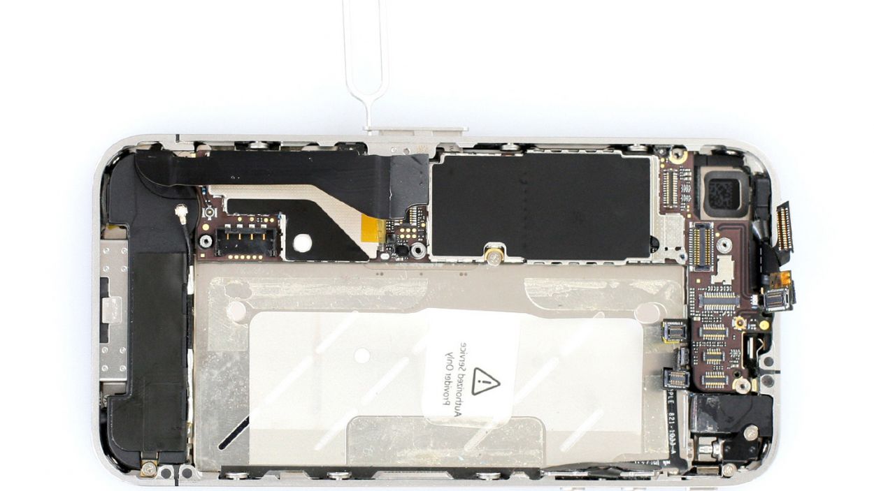
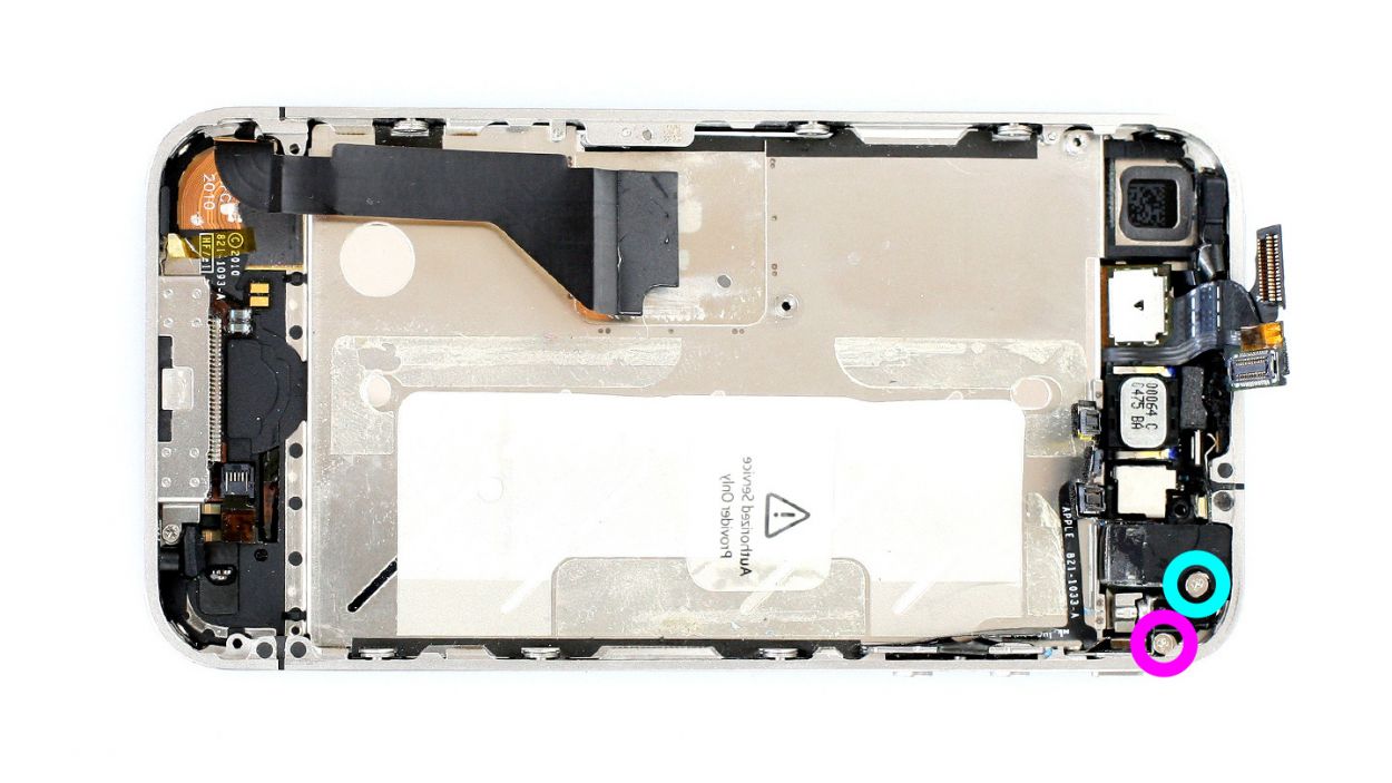
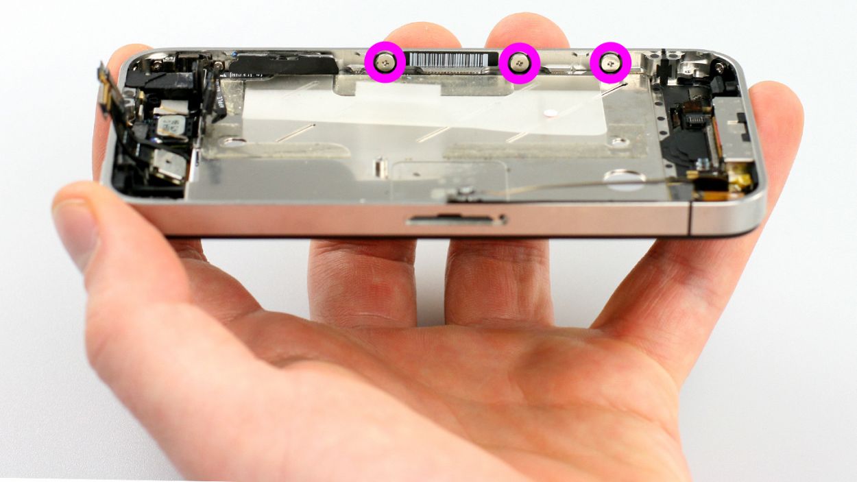
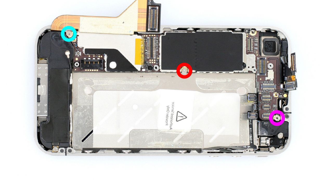
– First, let’s get those three screws that are keeping the logic board snug in its spot. Unscrew them with care!
– You’ll want to grab your trusty Phillips screwdriver and either a flathead screwdriver or a lab spatula (check out figure 1 for a visual). Keep those screws safe in the same compartment of your organizer tray. They’re a mixed bag, so it’ll be easy to identify them: 1 x 4.8 mm Phillips/flathead screw, 1 x 2.4 mm Phillips screw, and 1 x 2.0 mm Phillips screw.
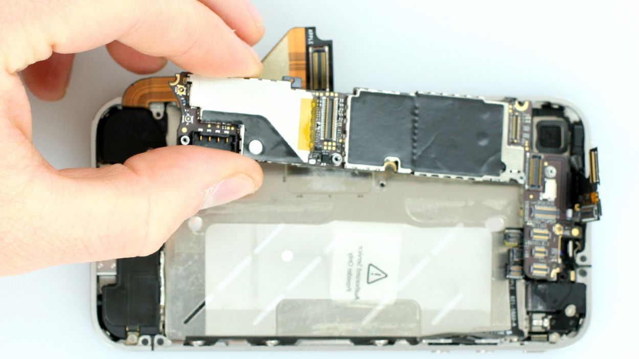
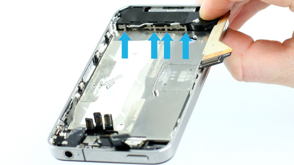
– Now, gently lift the logic board from below the battery connection using the spudger (see figure 2), and carefully remove it by hand (see figure 3).
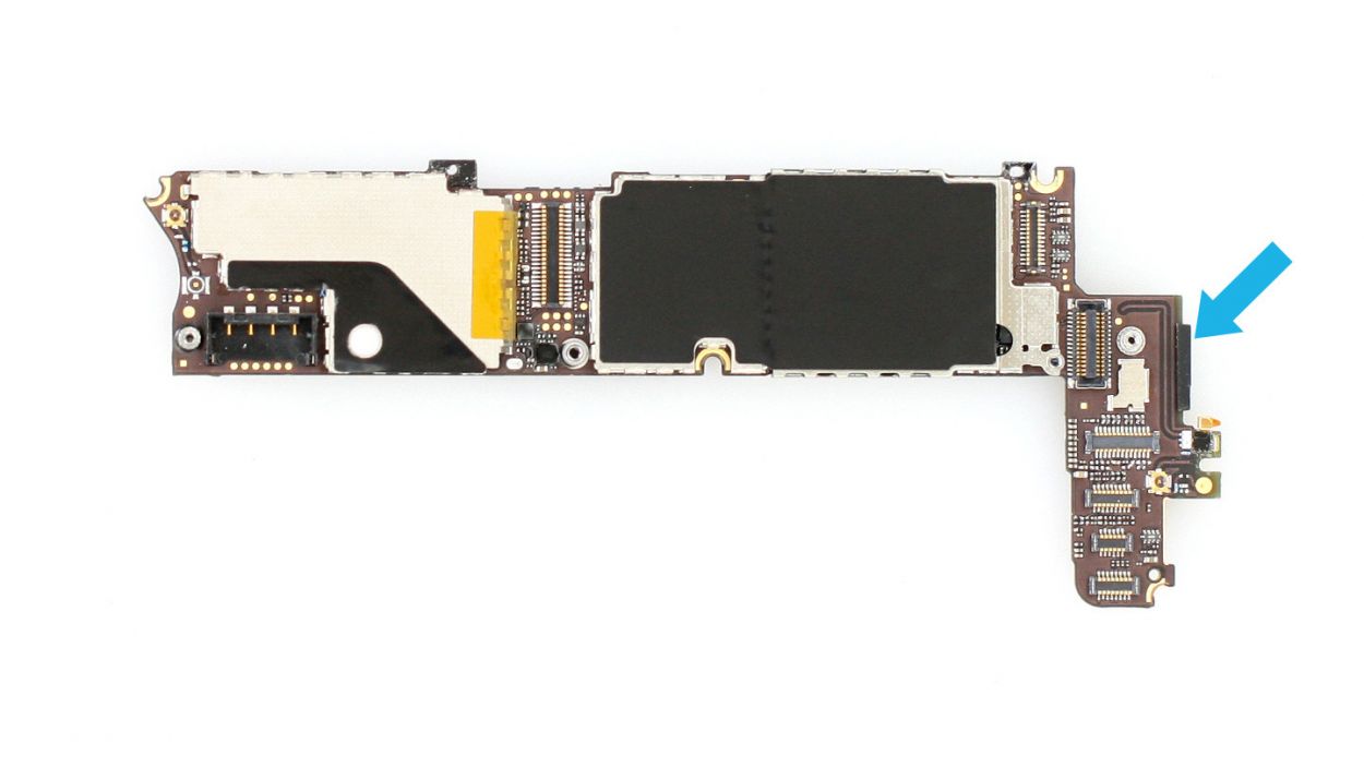
– Oh, and don’t forget about that little black rubber protector on the right side of the logic board (see figure 4). It comes off without a fuss! Just keep it with the screws from this step so it doesn’t wander off.
Step 13
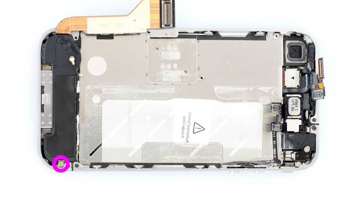
– Unscrew the remaining Phillips screw on the speaker (see figure 1) and use the spudger to remove it (see figure 2). Put the screw in a separate compartment of your organizer tray.
Step 14
– Time to say goodbye to that vibration motor! First, grab your Phillips screwdriver and unscrew those two screws holding it in place. Make sure to keep those little screws snug in the same compartment of your organizer tray. You’ll need 1 x 6.0 mm Phillips screw and 1 x 1.3 mm Phillips screw for this step!
Step 15

– Now, with a gentle touch, loosen those six identical Phillips screws (three on each side) just a couple of turns. Remember, we’re talking about 6 x 1.5 mm Phillips screws here!
– No need to take them out completely; just a little wiggle will do. This way, putting your phone back together will be a breeze later on!
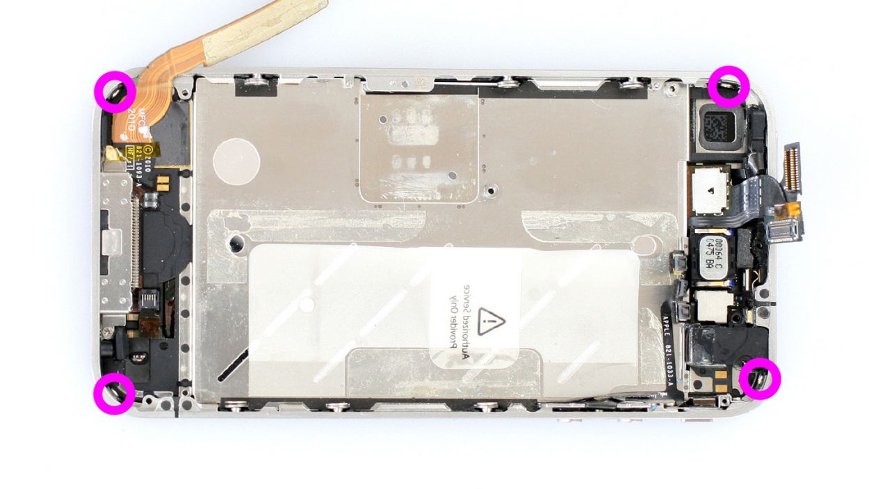
Step 16


– The identical Phillips screws in the four corners of your iPhone are still holding the display in place. Time to give them the boot! Remove those screws completely and tuck them away in the same cozy compartment of your organizer tray. You’ve got 4 x 1.6 mm Phillips screws to deal with here!
Step 17
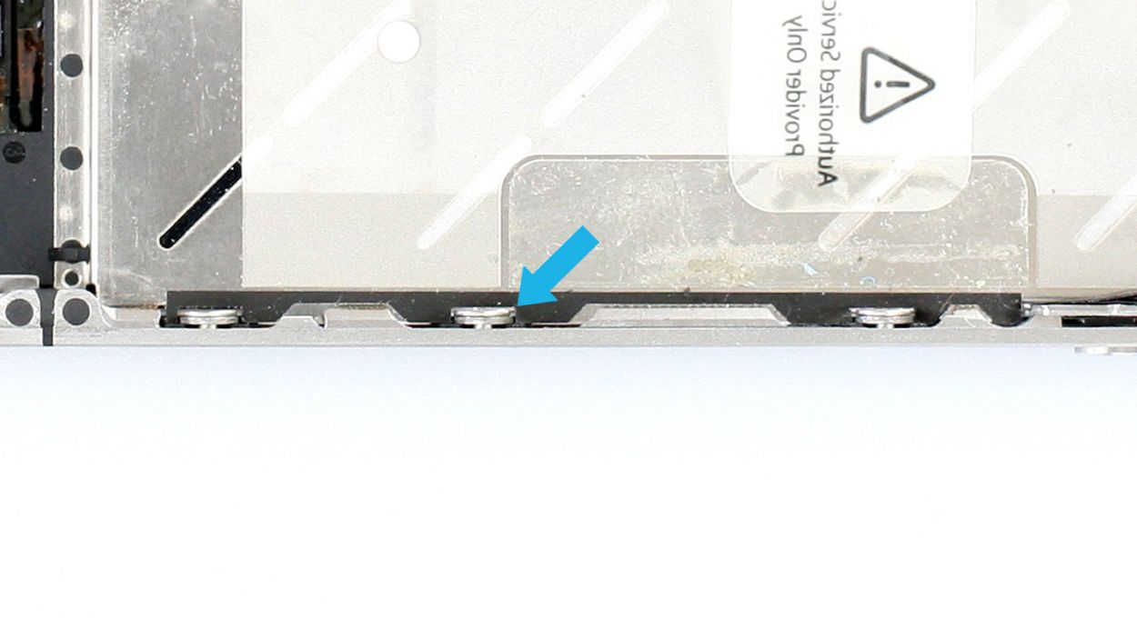
– To get things rolling, warming up the front of the display at the top and bottom with a heat gun or hair dryer can really help soften that stubborn glue (check out figure 1 for a visual!).
– Next, take the flat end of your trusty spudger and gently slide it about 2 to 3 mm between the display assembly and the silver frame, lifting the screen slowly. If you’re using a different tool, just be careful not to scratch the front panel from the inside. This is super important if you’re swapping out the Home button’s flexible flat cable since you’ll be using the same screen.
– Start your mission between the headphone output and the standby button (see figure 2). As soon as you see a little gap, go ahead and try to lift off the display with your fingers. Remember, the glue’s strength can be a bit unpredictable.
– Using that spudger, make your way around the entire frame once (see figure 3). If the display is still playing hard to get, don’t hesitate to apply a bit more hot air.
– Keep warming it up until you can easily lift the display assembly (check out figure 4) and it’s no longer stuck. Just a friendly reminder: the display’s connection cables are located on the side with the standby button.
Step 19
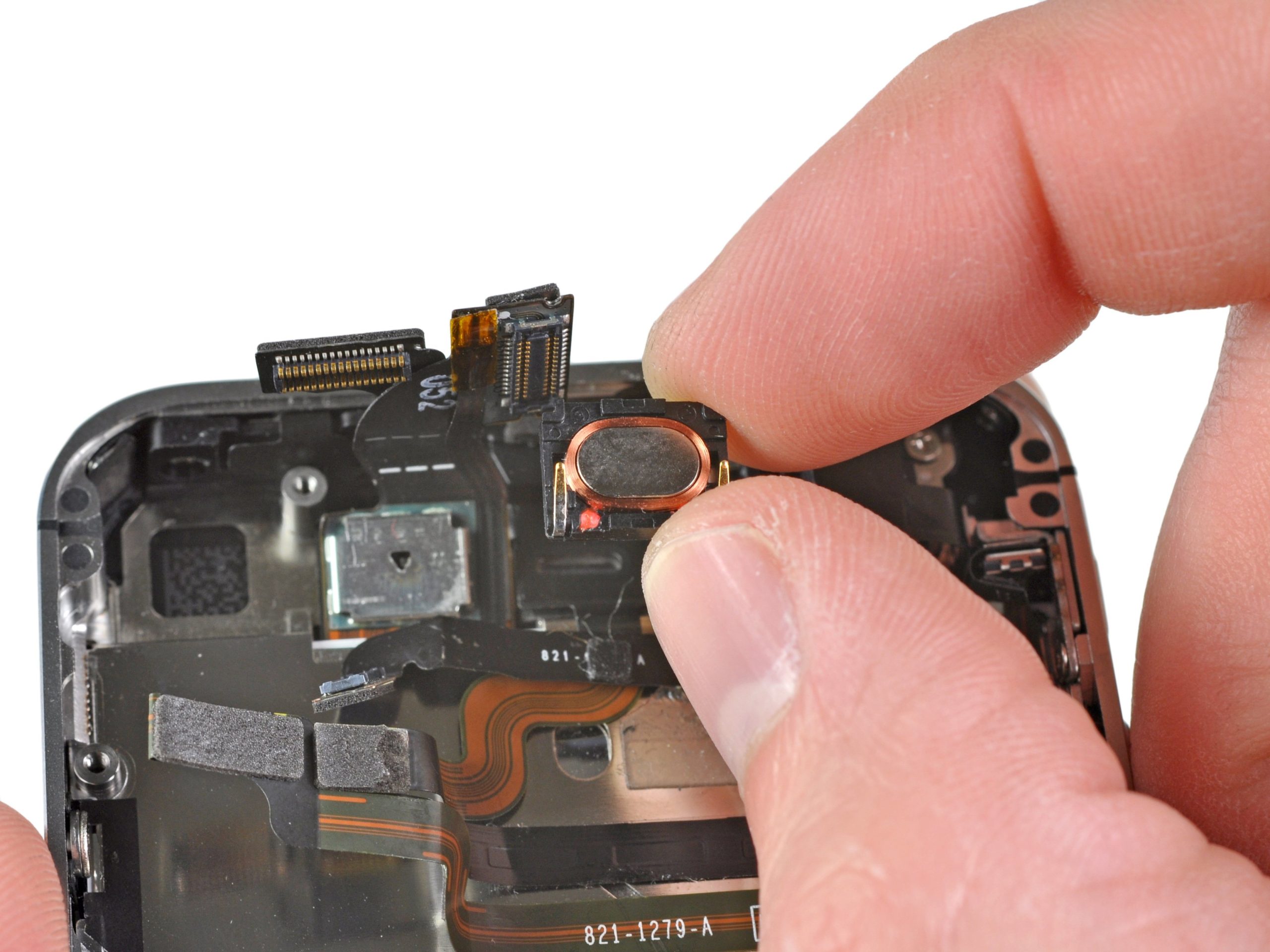
– Slide that trusty laboratory spatula under the sticky adhesive film hugging the earpiece’s foam ring. Just a friendly reminder: steer clear of the cable set while you’re at it!
– Now, give that earpiece a gentle wiggle until it’s ready to make its grand exit!
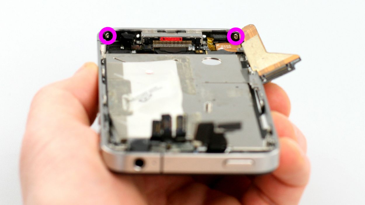
Step 20

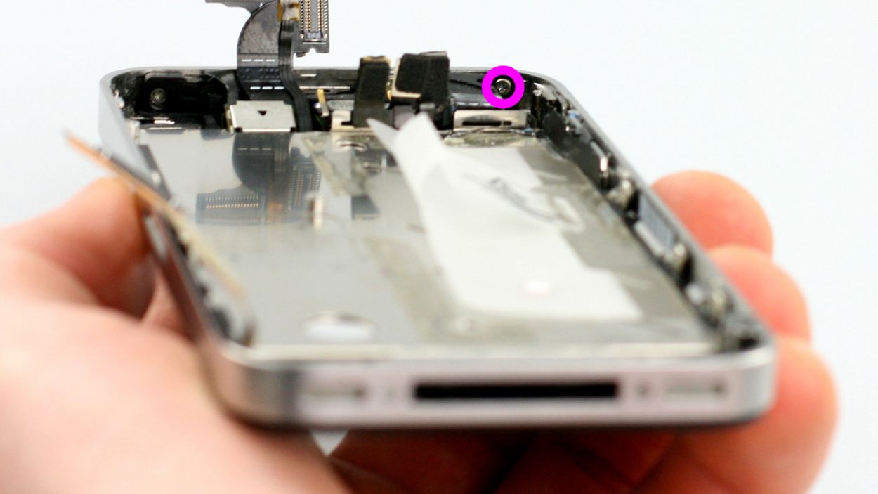
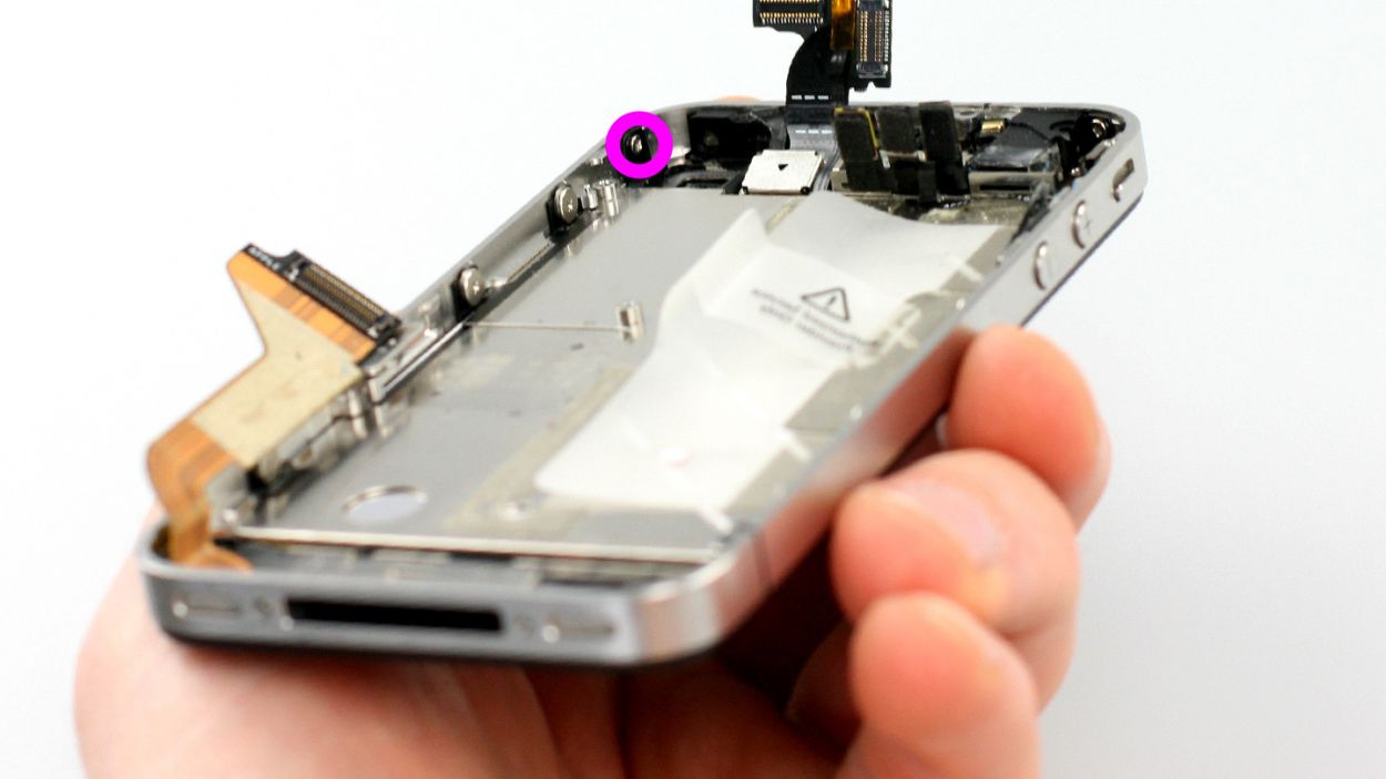
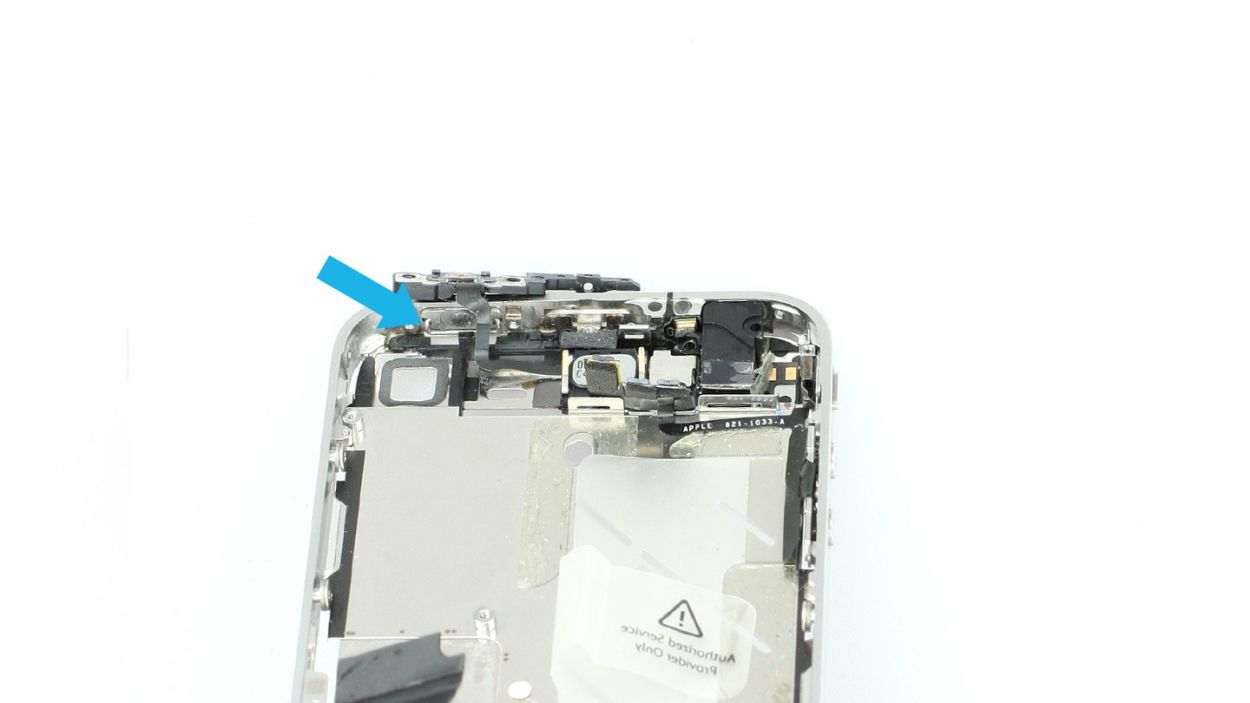
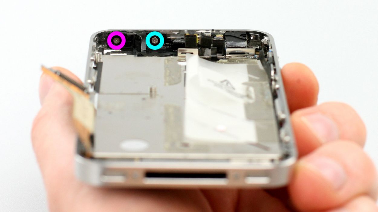
– Unscrew those two Phillips screws that are keeping the standby support frame snug against the standby button. Don’t forget to toss them into the same cozy compartment of your organizer tray! You’ll need a 1 x 1.4 mm Phillips screw and a 1 x 1.0 mm Phillips screw for this step.
Step 21
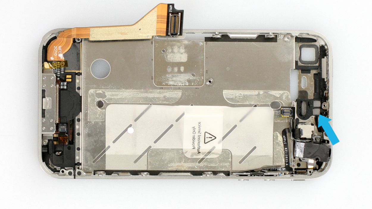
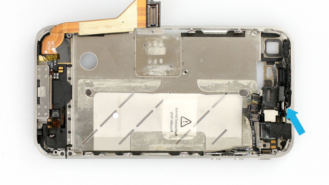
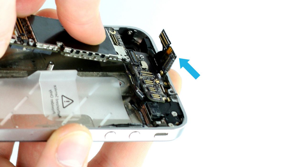
– First, let’s free up that headphone output so we can easily access the ambient microphone (check out figure 1).
– Now, grab your trusty laboratory spatula and gently pry the ambient microphone off the frame. It’s got a bit of glue holding it down (see figure 2).
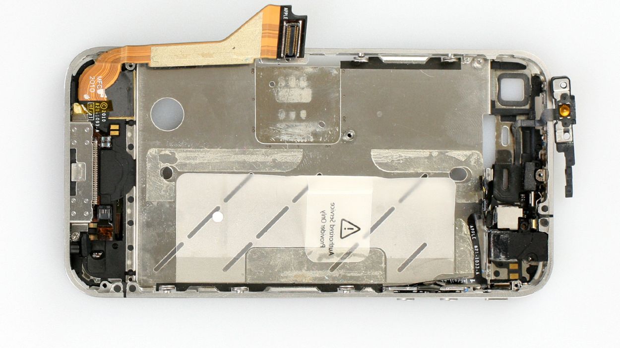
– Next, use the spatula to detach the remaining cable set (figure 3 will guide you).
– Finally, use your fingers or tweezers to carefully remove the cable set from its cozy spot (see figure 4).
Step 22
– Time to gather up some parts for the mission ahead!
Step 23
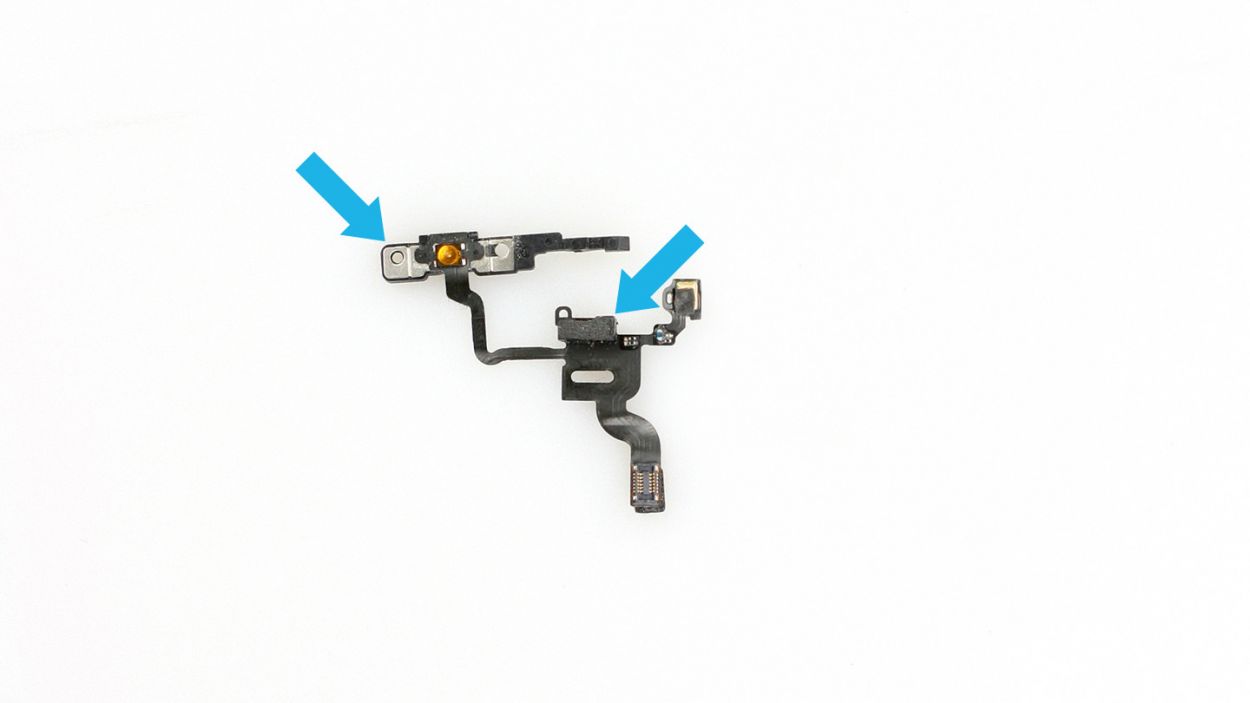
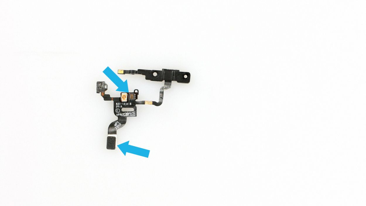
– Gently place the cable set in such a way that the two sensors nestle into their cozy recesses (check out figure 1 for guidance!).
– Pop the ambient microphone back into its original spot and slide in the headphone output (see figure 2 for a visual).
– Make sure the rocker frame for the standby button is facing downwards (figure 3 is your friend here). Now, it’s time to put the standby support frame back in place so you can secure it with screws. The end with the copper plate should be positioned behind the metal rocker switch (figure 4 will show you how).
Step 24
– Alright, it’s time to secure those two Phillips screws back in their cozy spots! You’ll need 1 x 1.4 mm Phillips screw and 1 x 1.0 mm Phillips screw for this step. Let’s make sure everything is snug and ready to go!
Step 25

– Once you’ve got that assembly snugly on the frame, give the Home button a little tap. It should respond just like it always does! And don’t forget to check that the display is sitting pretty on the frame (take a peek at figure 3).
– Now, let’s ensure those washers for the six identical Phillips screws are in their right spots (see figure 4). Remember, the display’s clips should be cozy between the washer and the frame!
Step 26


– Time to screw in all four of those equally sized Phillips screws again. You’ve got 4 x 1.6 mm Phillips screws ready to go!
Step 27


– Now you have to tighten the six identical Phillips screws (three on each side).6 x 1.5 mm Phillips screws
Step 28

– First, gently place that vibration motor back where it belongs and secure it with the screws (check out figure 1 for a visual!). You’ll need 1 x 6.0 mm Phillips screw and 1 x 1.3 mm Phillips screw for this step.
– Just a friendly reminder: make sure the adhesive film on the headphone output doesn’t get too cozy with the vibration motor’s head. If they end up in a sticky situation, the motor won’t be able to dance freely (see figure 2 for guidance).
Step 29

– To kick things off, give that Phillips screw on the speaker a gentle snugging (check out figure 1 for a peek). You’ll be using a 1 x 2.4 mm Phillips screw for this step!
– Next up, make sure the speaker’s clips are snugly against the speaker, just behind the higher level of the middle cover (see figure 2). It’s a breeze if you’ve only lightly tightened the speaker screw, allowing it to wiggle a bit.
– Once everything is lined up just right with the clips, go ahead and tighten that screw like a pro!
Step 30

– First, let’s get that rubber protector back on the sharp edge of the logic board. Make sure the thicker side is facing down (check out figure 1 for a visual!).
– Next up, gently place the logic board back in its cozy spot as shown in the picture. It should click into place when everything’s lined up just right (see figure 2). Don’t worry if it takes a few tries! Use figure 3 to double-check that your logic board is snug and make sure that antenna cable from the speaker isn’t hiding beneath it.
– Finally, it’s time to secure the logic board! Grab your Phillips screwdriver and fasten all three screws to keep everything in place (see figure 4). You’ll need: 1 x 4.8 mm Phillips/flathead screw, 1 x 2.4 mm Phillips screw, and 1 x 2.0 mm Phillips screw.
Step 31
– Pop that cheeky white water indicator sticker back onto the Phillips screw like it’s meant to be there!
Step 32

– First, connect the camera and then plug in the other connectors to their matching spots. Just give them a gentle press with your finger until you hear that satisfying click! No need to go all Hulk on them—just enough pressure to get them settled in nicely.
– If you find that the LCD/touchscreen cable is feeling a bit short, it might be because you forgot to pull it snugly through the midframe slot. No worries, just give it a little tug!
Step 33
– Place the cover back onto the logic board and ensure it’s snugly hooked on—no loose ends here!
– Next, secure it with five Phillips screws (check out figure 1 for a visual). Here’s the screw lineup: 1 x 2.3 mm Phillips screw, 2 x 1.6 mm Phillips screws, 1 x 4.8 mm Phillips Wi-Fi screw, and 1 x 1.3 mm Phillips screw.
– If you notice any Wi-Fi signal hiccups later on, double-check that the Wi-Fi screw is tightened correctly. Also, make sure the Wi-Fi contact point is properly seated on the cover (see figure 2 for a handy reference).
Step 34
– Reconnect that dock connection cable and give it a stylish black or silver cover to keep it cozy.
– Now, let’s tighten up those two Phillips screws once more. You’ll need 1 x 1.2 mm Phillips screw and 1 x 1.6 mm Phillips screw to make it all snug again!
Step 35

– Give that cheeky plastic tab with the warning a little tug to detach it, or if you’re feeling nostalgic, just pop it back in if you pulled it out. It’s all about keeping things tidy while you work your repair magic!
Step 36
– First, reconnect that antenna connector like a pro (check out figure 1 for a little visual cue).
– Next up, gently slide the battery back into its cozy home inside the iPhone.
– Now, let’s get that antenna cover back on (see figure 2 for guidance).
– Finally, snap the battery connector back into place and secure it with a screw (figure 3 will show you the way). You’ll need a 1 x 2.6 mm Phillips screw for this step!
Step 37

– Carefully place the back cover back on your iPhone and give it a gentle push the last few millimeters towards the dock connector. You’ve got this!
Step 38
– Now, let’s get those two screws at the bottom of the enclosure all snugged up! You’ll need 2 x 3.6 mm pentalobe/Phillips screws for this step. Easy peasy!
– Next, just give the SIM card tray a gentle push to pop it back in. You’re almost there!
Step 39

Heads up! When you take out the battery, your iPhone might decide to throw a little time party and reset to 1:00 a.m. on 1/1/1970. If that happens, you might find yourself struggling to connect to the cellular network until you set the time right. So, let’s get that clock back on track!
– Sync up your iPhone with iTunes or hop onto a WLAN network and chill until the time is all set.
– Take out the SIM tray with the SIM card and pop it back in.
– Turn on airplane mode for a sec, then turn it off again. Easy peasy!