iPhone 4s – Replacing the screen
Duration: 90 min.
Steps: 35 Steps
In this guide, we show you how to replace your iPhone 4s’ defective display unit. You need this repair if the glass is cracked, the touchscreen no longer responds to touch, or the LCD remains black or flickers. In this guide, we show you how to replace your iPhone 4s’ defective display unit. You need this repair if the glass is cracked, the touchscreen no longer responds to touch, or the LCD remains black or flickers.
Step 1
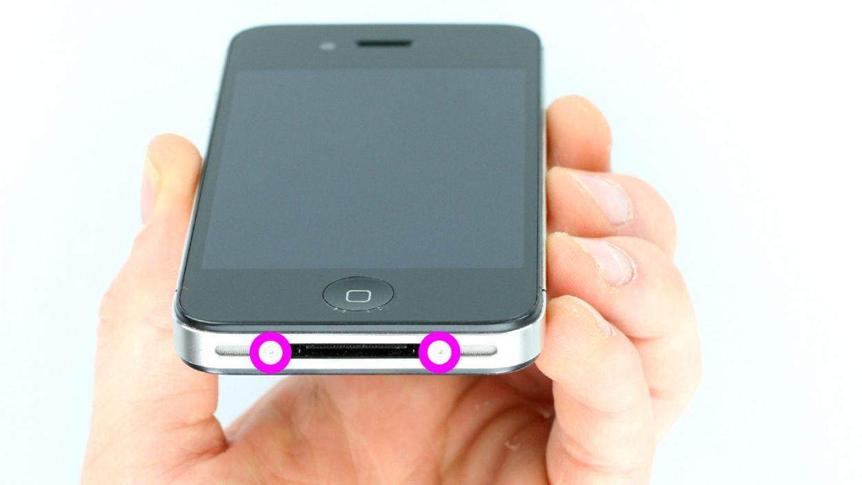
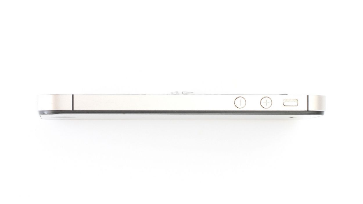
– You need a pentalobe screwdriver to open your phone.
– Remove the two pentalobe screws at the bottom of the enclosure. They are located to the right and left of the dock connector. Put the screws in the same compartment of your organizer tray.2 x 3.6 mm pentalobe screws
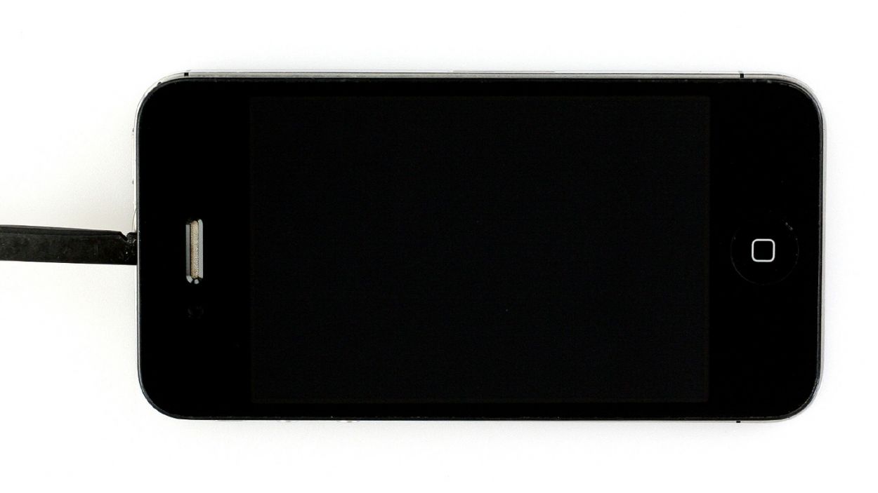
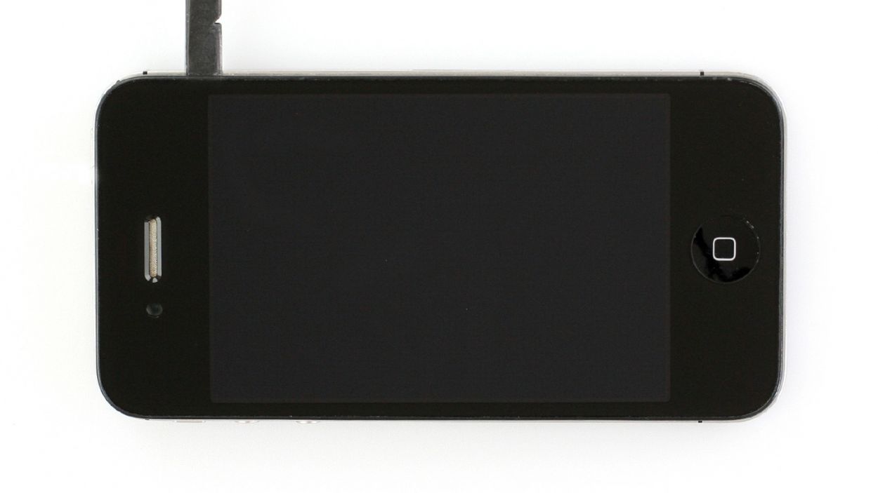
Step 2
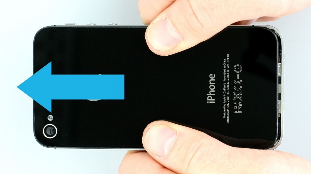
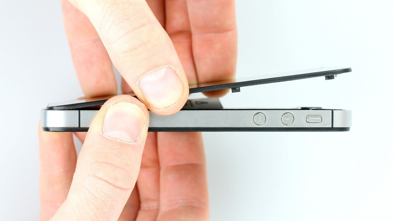
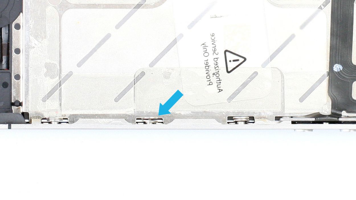
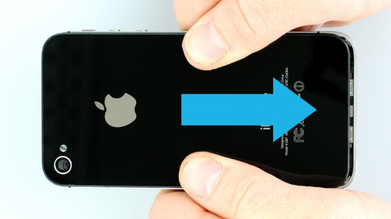
– Use your thumbs or the palm of your hand to push the back cover of your iPhone about 4 mm away from the bottom of the phone where the dock connector is (see figure 1).
– Then you can lift the back cover at the end that’s sticking out past the phone (see figure 2).
Step 3

The contact point on the logic board could come off. If the contact point breaks off but the soldering points are still intact, you can solder the contact point back on.
– First things first, if your iPhone is still awake, give it a little nap! Hold down that standby button for about five seconds and follow the friendly prompts on the screen.
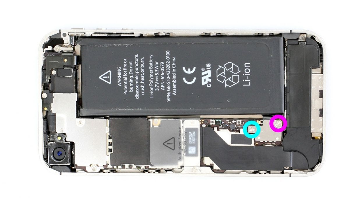
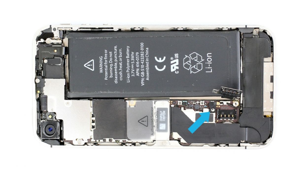
– Next up, grab your trusty Phillips screwdriver and remove the two Phillips screws from the battery connector (check out figure 1 for guidance). Make sure to place those screws in the same compartment of your organizer tray. Just a heads-up, one screw is 1 x 1.5 mm and the other is 1 x 1.3 mm. Oh, and be careful—if the contact point on the logic board decides to take a vacation, you can always solder it back if the soldering points are still intact.
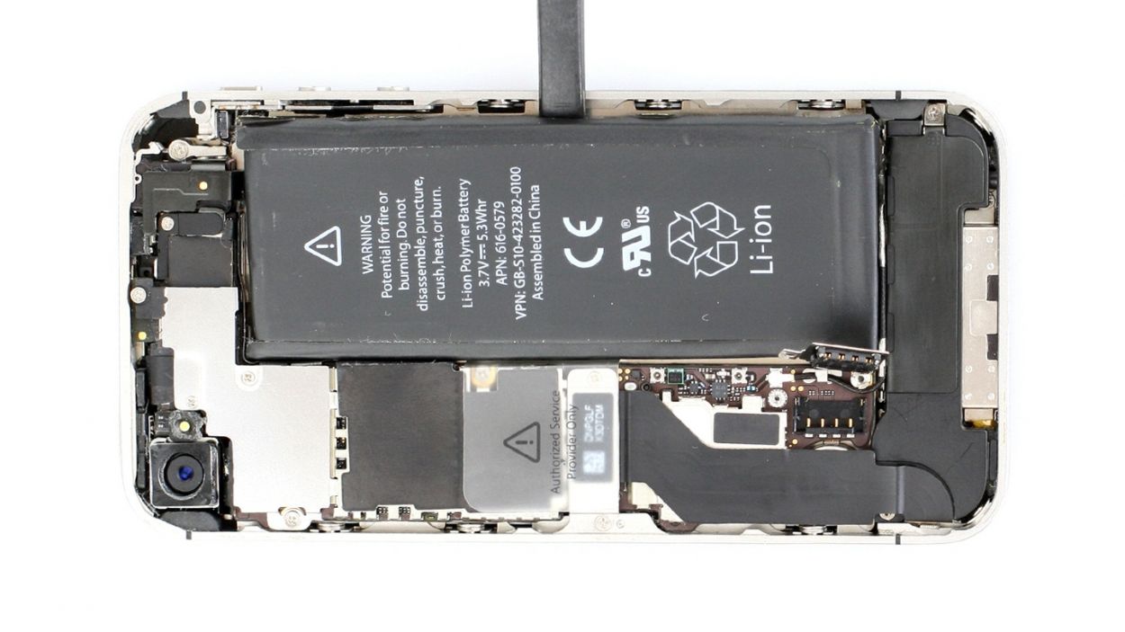
– Now, it’s time to gently lift off that battery connector! Use the pointed ESD spudger and slide it just below the silver cover plate (figure 2 will help you out). If you don’t have a spudger handy, your fingernail can do the trick too—just be gentle!
– For the remainder of your repair adventure, feel free to swap in a metal laboratory spatula instead of the spudger. It might make some steps a bit easier. But hey, we really recommend sticking with the ESD spudger designed for precision electronics—it’s the superstar of the repair world!
Step 4

– The antenna cover is under the battery connector. Remove the cover and put it in the same compartment of your organizer tray as the Phillips screws you removed before (see figure 1).
– Now remove the battery. It’s sometimes glued firmly in place. Insert the flat end of the spudger into the space (about 1 cm to the left of the volume down button) between the battery and the outer frame, and slowly lift the battery (see figure 2). If the battery’s really stuck on, use other leverage points to the right and left of the original spot to pry it off. If you still can’t detach the battery, you can use a heat gun to warm it slightly from the outside and soften the glue.
– Now you can also disconnect the antenna connector by carefully pulling it off the plug head using the spudger (see figure 3).
Step 5


– Fold the plastic tab with the warning over and press it firmly onto the lower adhesive strip. This way, it won’t get in the way during your repair.
– Of course, you can also remove the plastic tab.
Step 6


– Remove the two Phillips screws from the dock connection cable and remove the silver cover (see figure 1).1 x 1.1 mm Phillips screw1 x 1.4 mm Phillips screw
– Put the screws and cover in the same compartment of your organizer tray. It’s easy to tell them apart.
– Now you can carefully detach the connector by using the pointed tip of the spudger to lift the connector. Alternatively, you can also use your fingernail again (see figure 2).
– Pull the flat cable that’s lightly glued in place off of the logic board and bend it carefully over the frame (see figure 3).
Step 7


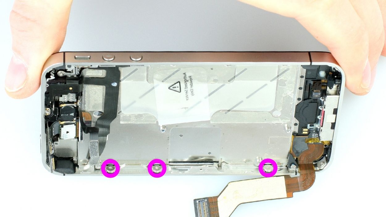
– Remove the four Phillips screws from the cover (see figure 1). Put the screws in the same compartment of your organizer tray. It’s easy to tell them apart.1 x 2.6 mm Phillips screw2 x 1.2 mm Phillips screws1 x 2.7 mm Phillips screw (thin thread)
– The cover is slightly clamped in place on the midframe (see figure 2). In order to remove the cover, use the spudger to push it slightly to the left, toward the dock connector (see figure 3).
Step 8


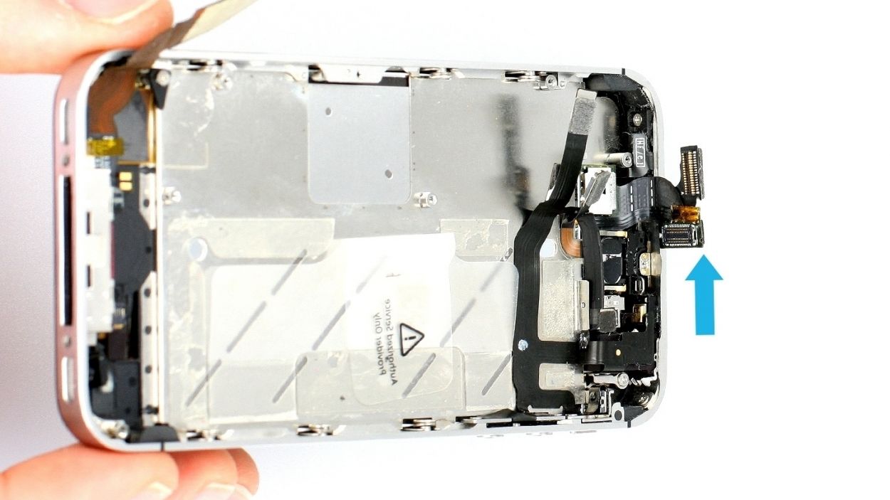
– Use the spudger to lift off the camera connector and remove the camera (see figure 1).
– Use a pair of tweezers or the laboratory spatula to remove the black sticker below the flash (see figure 2).
– There’s a Phillips screw below that. Remove it (see figure 3).1 x 2.6 mm Phillips screw
– Now remove the copper contact (see figure 4).
– Put all the parts in the same compartment of your organizer tray.
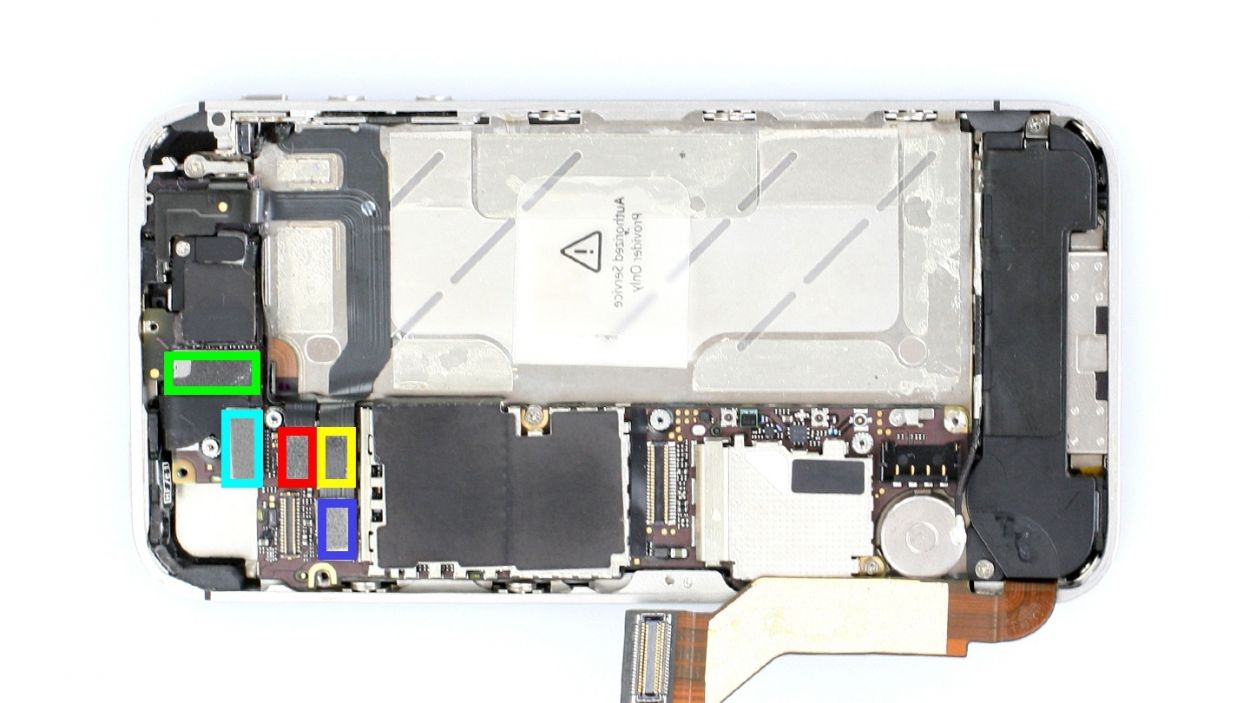
Step 9

Make sure you don’t break off the resistors that are soldered onto the logic board.
– Now you can disconnect the following five connectors. Be very careful.
– Place the pointed tip of the spudger very slightly below the contact and lift it up.
– Start with theconnector. There’s a secondconnector below it.
– Test the new display.Temporarily connect the new display assembly.Connect the dock connector, the connectors you disconnected previously and then the battery.Start the iPhone and check whether the LCD and touchscreen work properly. Make sure the connectors are securely plugged in to the connections.
– Temporarily connect the new display assembly.
– Connect the dock connector, the connectors you disconnected previously and then the battery.
– Start the iPhone and check whether the LCD and touchscreen work properly. Make sure the connectors are securely plugged in to the connections.
Step 10

– Remove the Phillips screw on the antenna cover (see figure 1). Put the screw in a separate compartment of your organizer tray.1 x 1.5 mm Phillips screw
– Now you can remove the cover of the antenna cable (see figure 2).Put it with the screw you removed before.
– Disconnect the antenna connector below it using the spudger (see figure 3).
Step 11

– You can use the SIM Tool or a paperclip to remove the SIM card tray. Press the SIM Tool into the small hole in the SIM card tray to remove it.
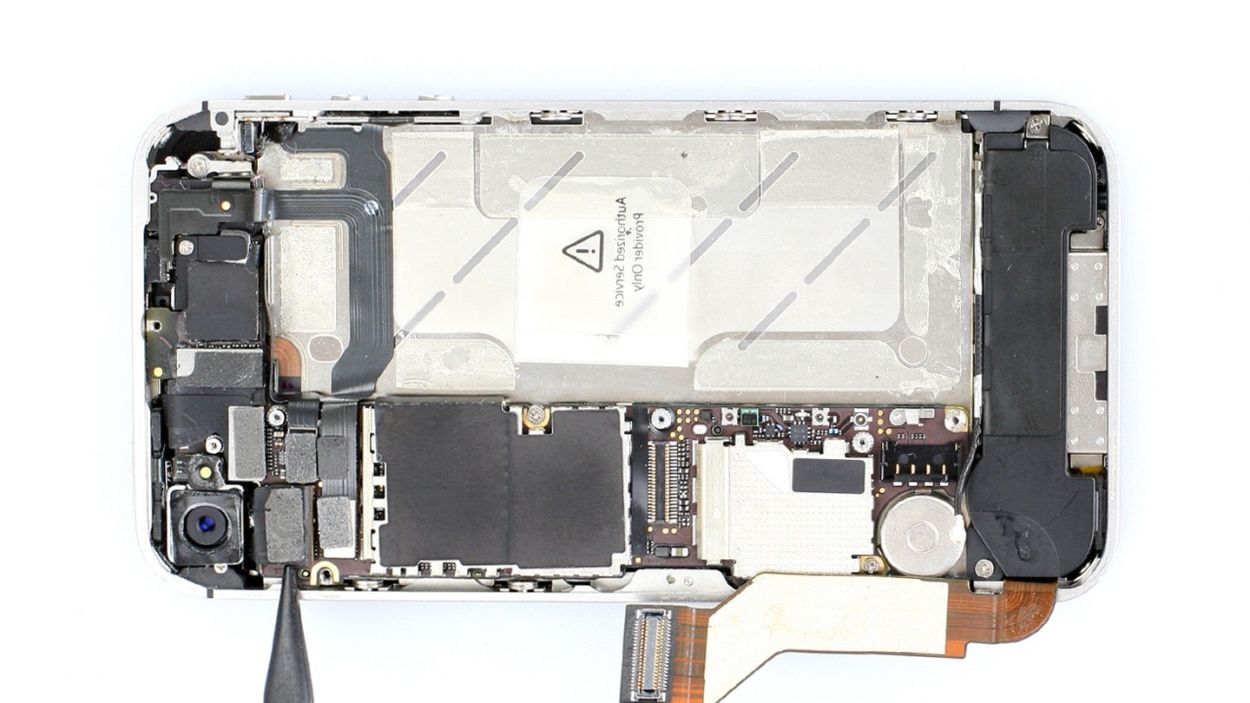
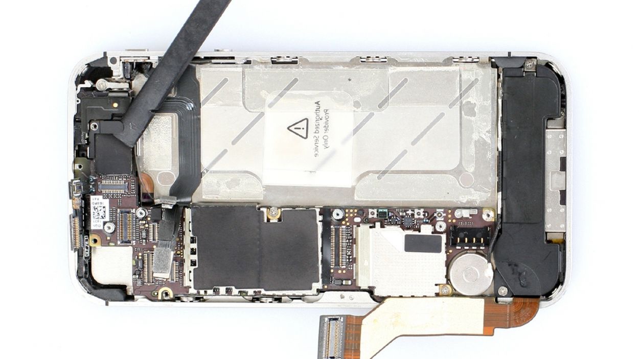
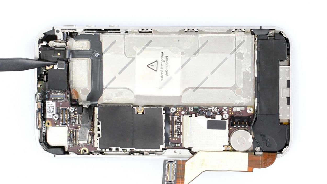
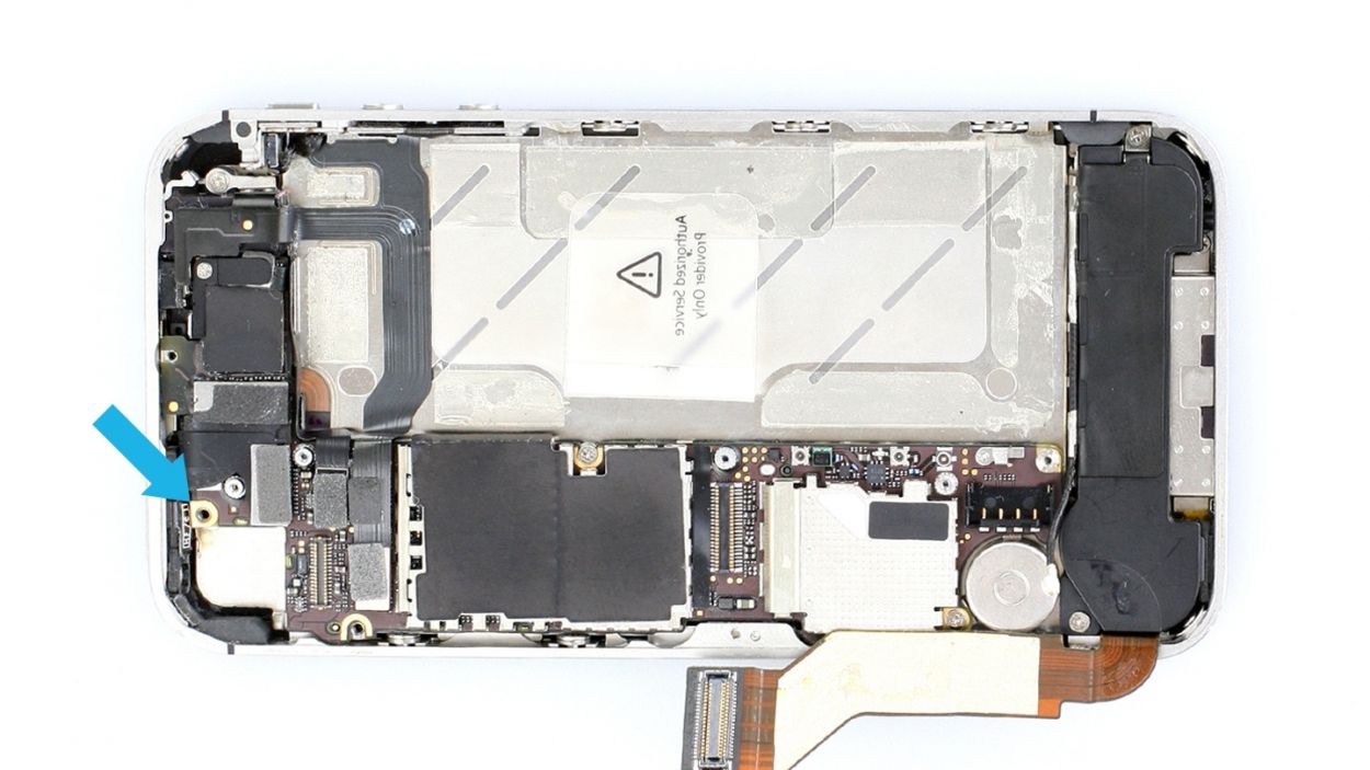
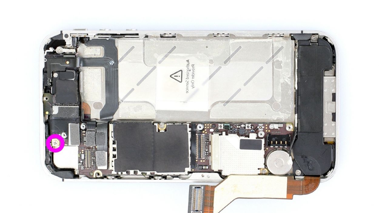
Step 12

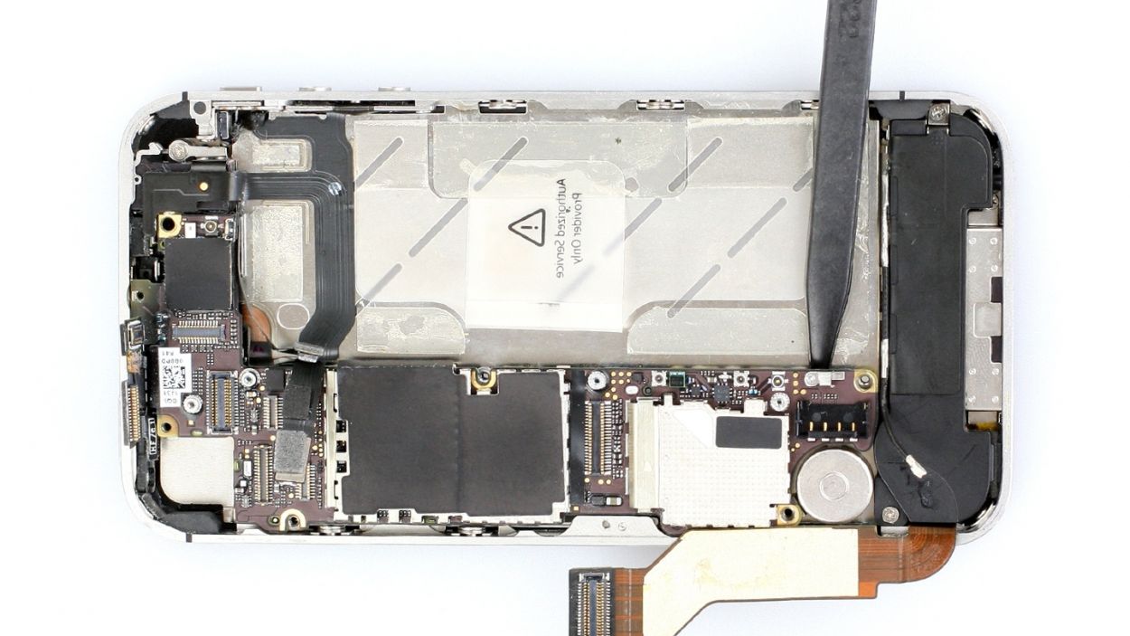


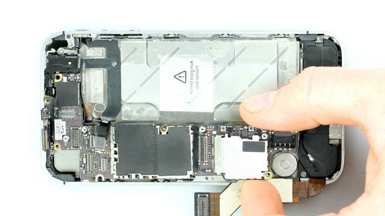
– Now unscrew all four screws that hold the logic board in place (see figure 1) and sort them as follows./and/in two different compartments of your organizer tray.
– You’ll need both the Phillips screwdriver and a flathead screwdriver or the laboratory spatula.1 x 4.9 mm Phillips/flathead screw1 x 2.4 mm Phillips screw1 x 2.6 mm Phillips screw1 x 3.7 mm Phillips/flathead screw
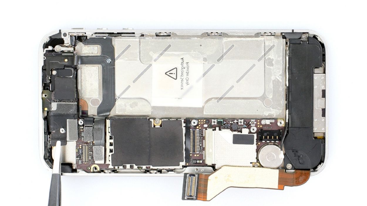
– Now you can carefully lift the logic board below the battery connection using the spudger (see figure 2) and remove it by hand (see figure 3).
– There’s a little black rubber protector on the upper end of the logic board (see figure 4). It comes off easily. Put it with the screws from this step so it doesn’t get lost.
Step 13
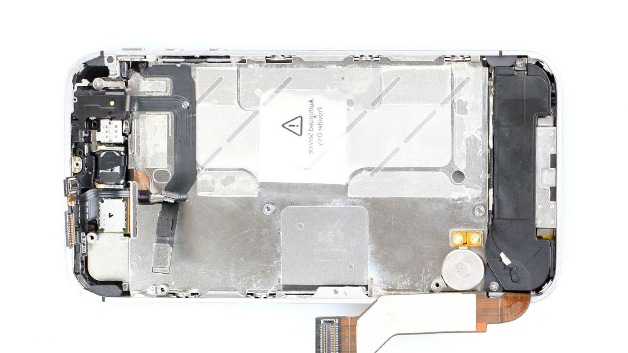
– Now remove the vibration motor.
– It’s glued firmly in place. It may help if you warm it up with a heat gun to soften the glue.
– Insert the spatula or spudger below the vibration motor and carefully lift it out.
Step 14

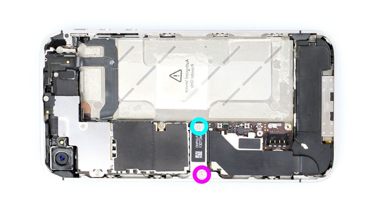
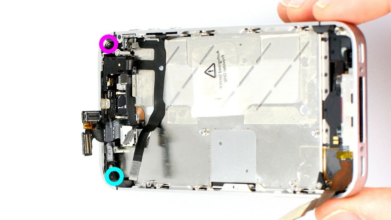
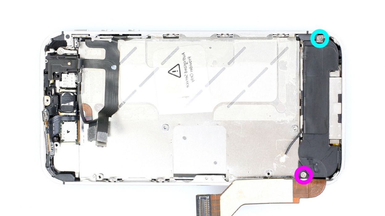
– Loosen the two Phillips screws on the speaker but only remove the one in the turquoise circle (see figure 1). This way, you won’t have to struggle to get the little black triangle back in later. Put the screw in a separate compartment of your organizer tray.1 x 2.5 mm Phillips screw (just loosen)1 x 2.5 mm Phillips screw
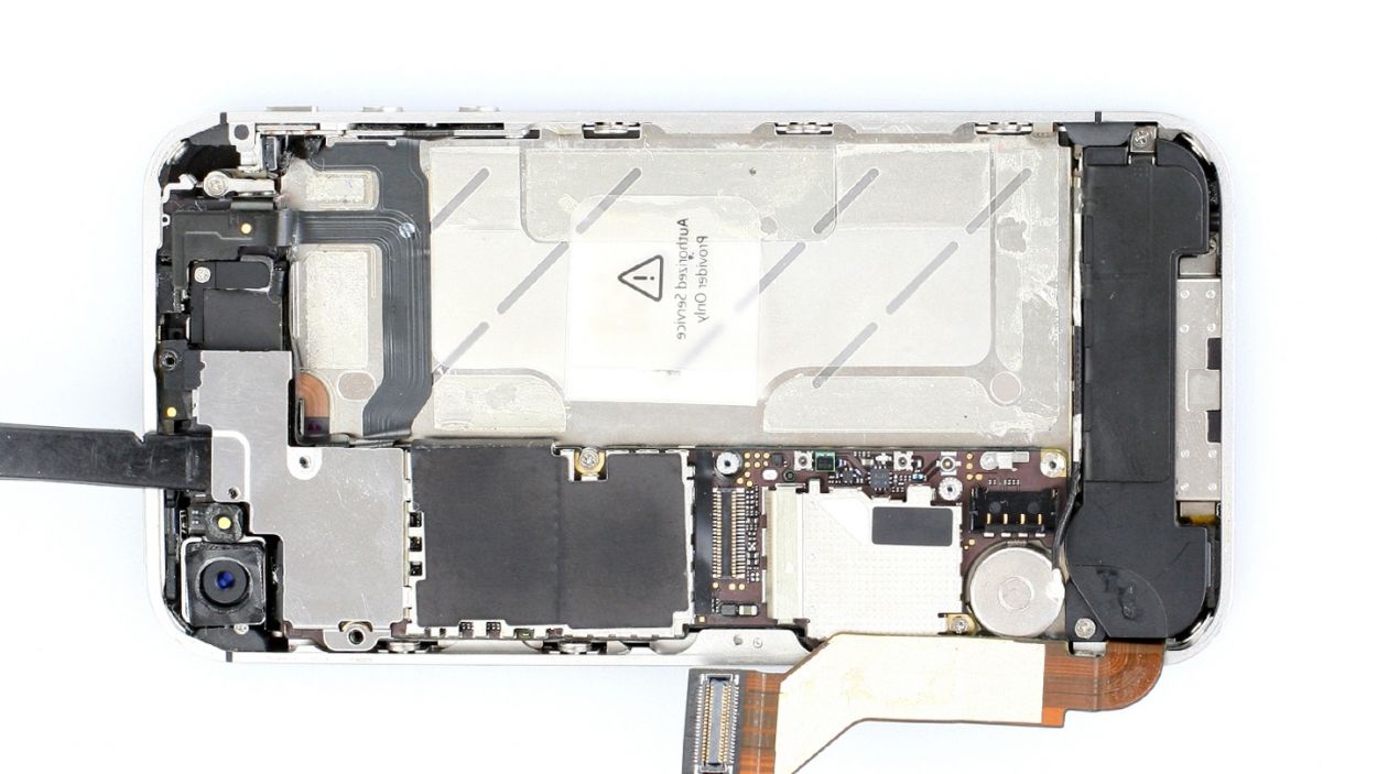
– Use the spudger to remove the speaker (see figure 2).
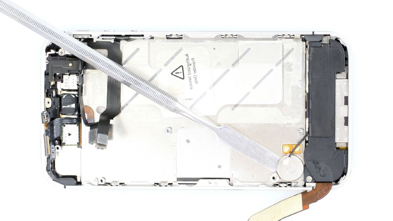
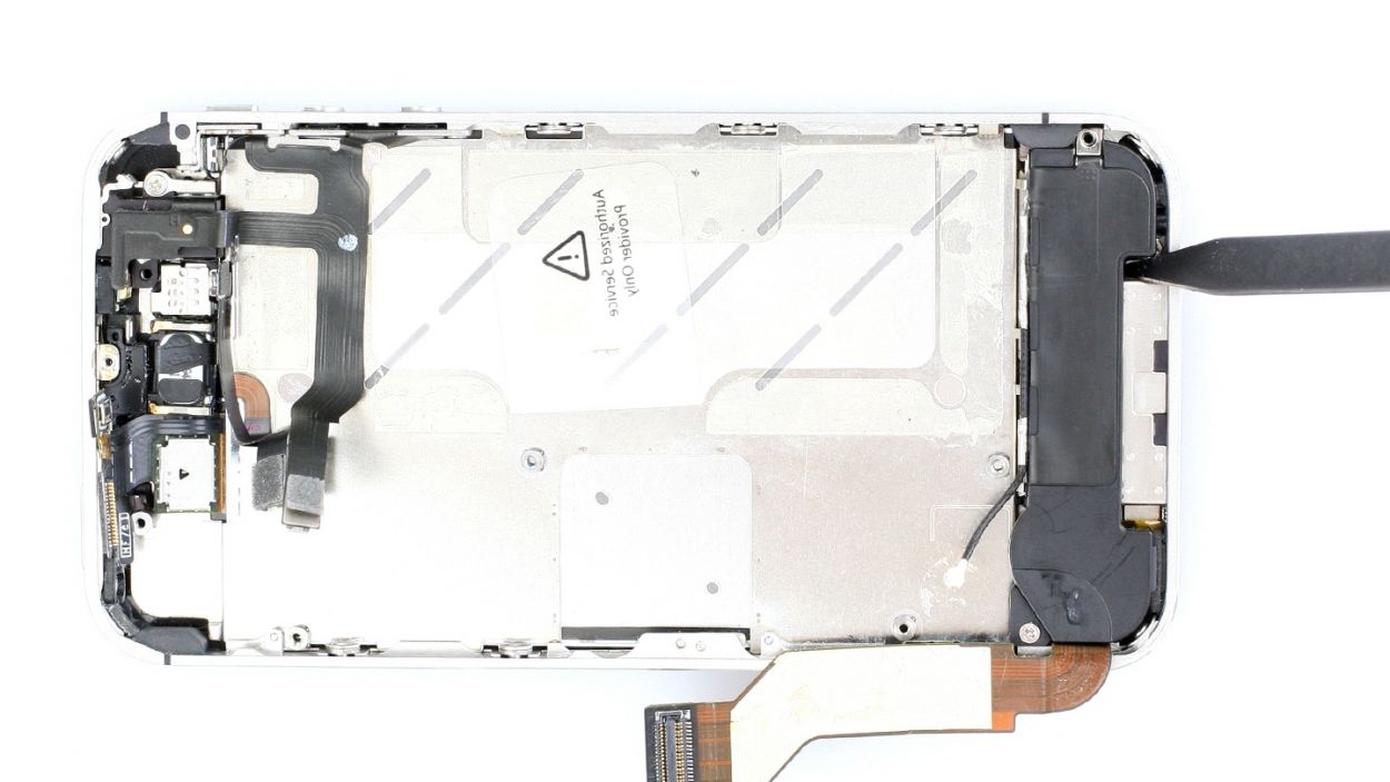
Step 15
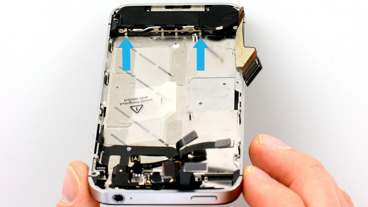
– Now carefully loosen the six identical Phillips screws (three on each side) by two or three turns.6 x 1.5 mm Phillips screws
– You don’t need to remove the screws completely. This way, it’ll be easier to put your phone back together later.
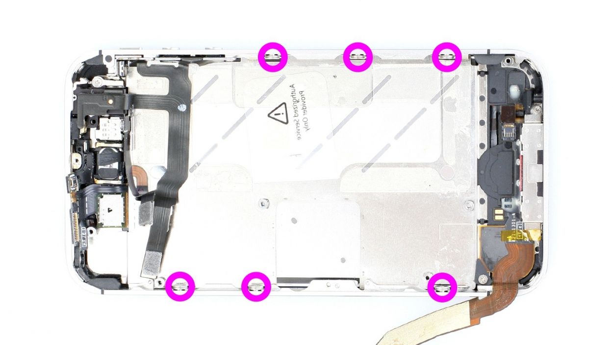
Step 16

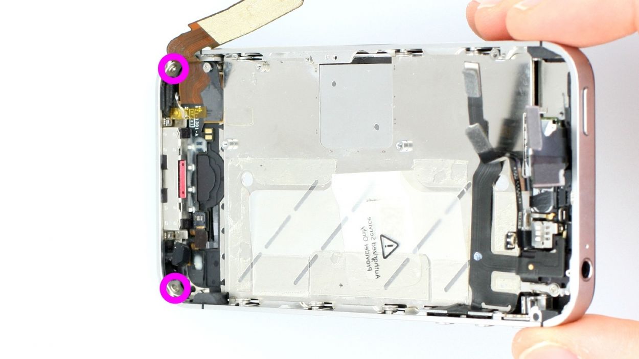
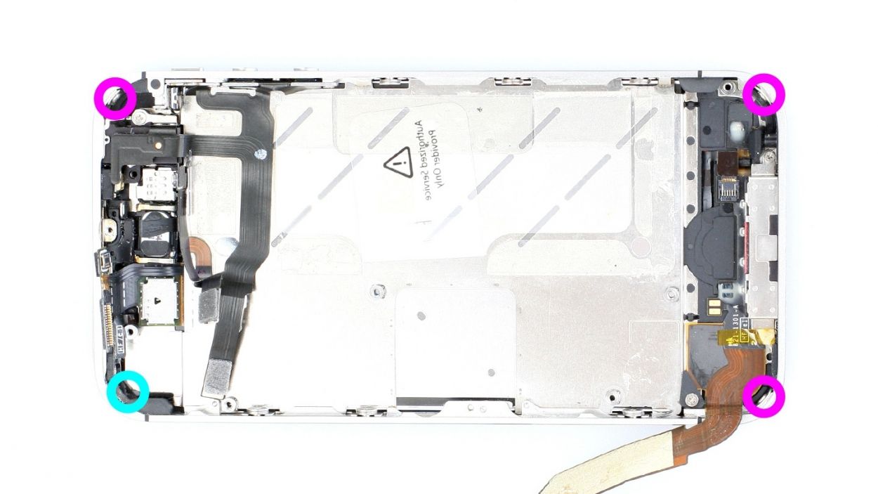
– The identical Phillips screws in the four corners of your iPhone are still holding the display in place.
– In the corner with the turquoise circle, this screw is under a sticker. You have to remove it first.
– Remove all four screws.3 x 1.6 mm Phillips screws1 x 1.6 mm Phillips screw
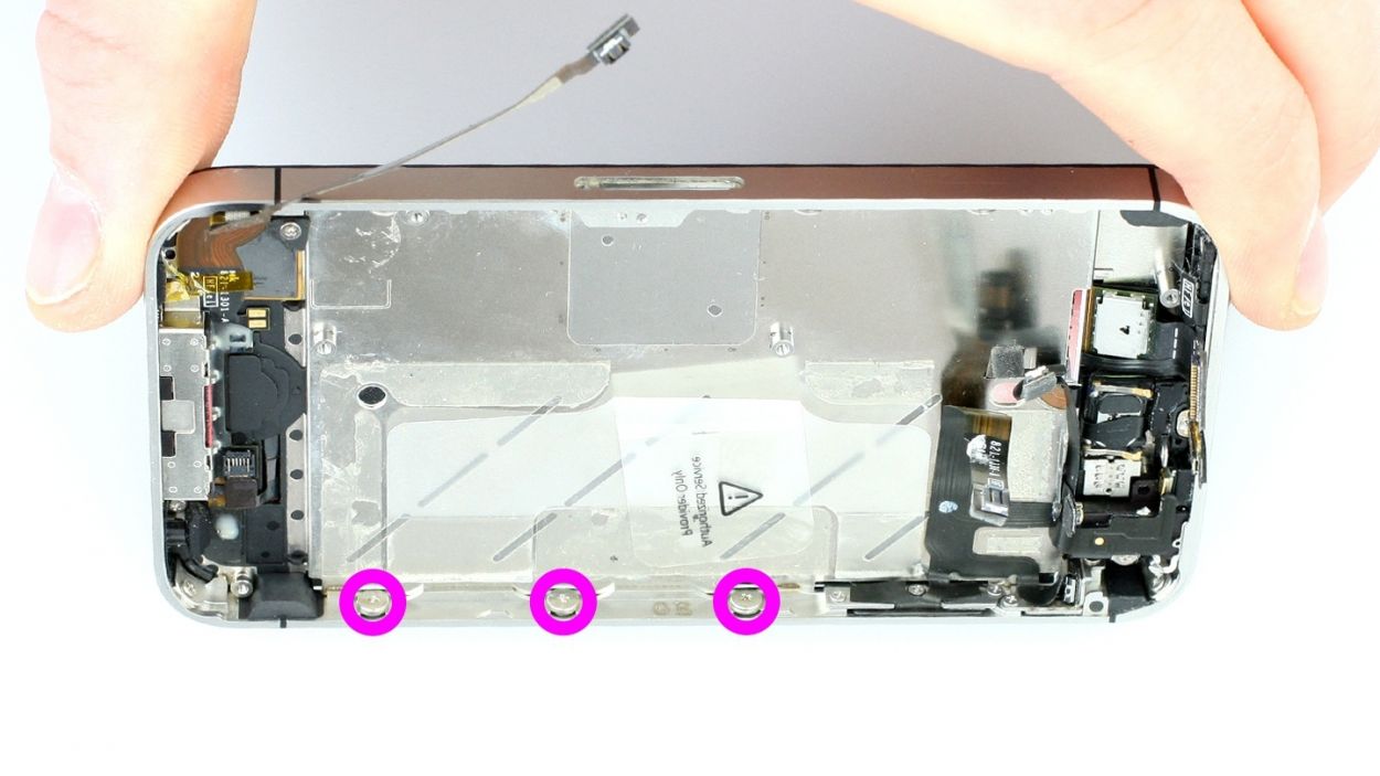
Step 17
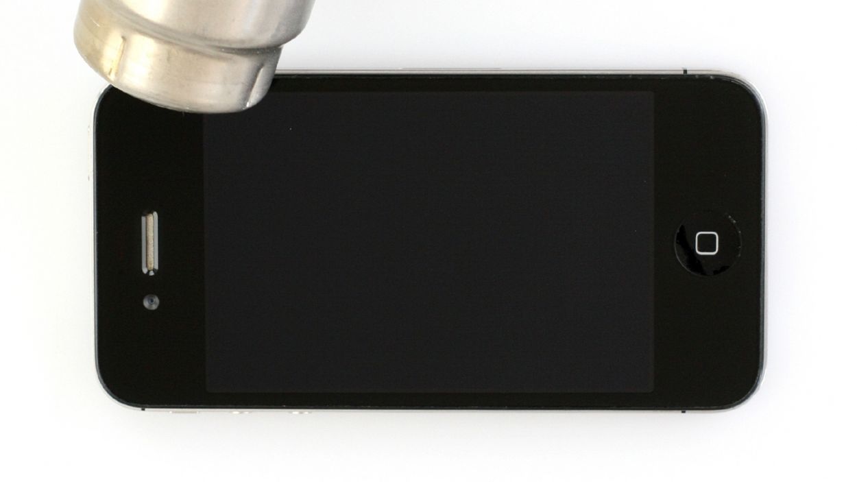
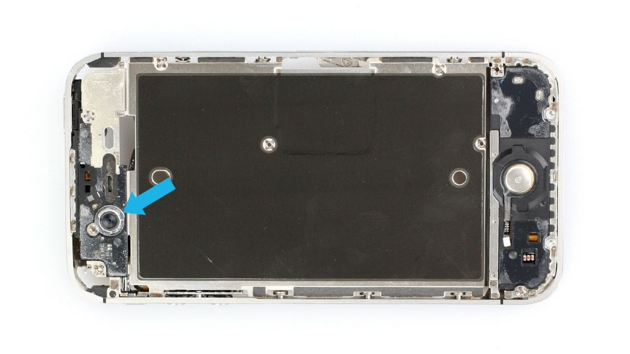
– It may help to warm up the front of the display at the top and bottom using a heat gun or hair dryer to soften the glue (see figure 1).
– Insert the flat end of the spudger about 2 to 3 mm between the display assembly and the silver frame, and slowly lift the screen. If you use a different pointed or flat tool, make sure you don’t scratch the front panel from the inside. This is especially important when you’re replacing the Home button’s flexible flat cable because you’ll be using the same screen.
– Start between the headphone output and the standby button (see figure 2). As soon as there’s a little gap, try to pull off the display with your fingers. The strength of the glue can vary greatly.
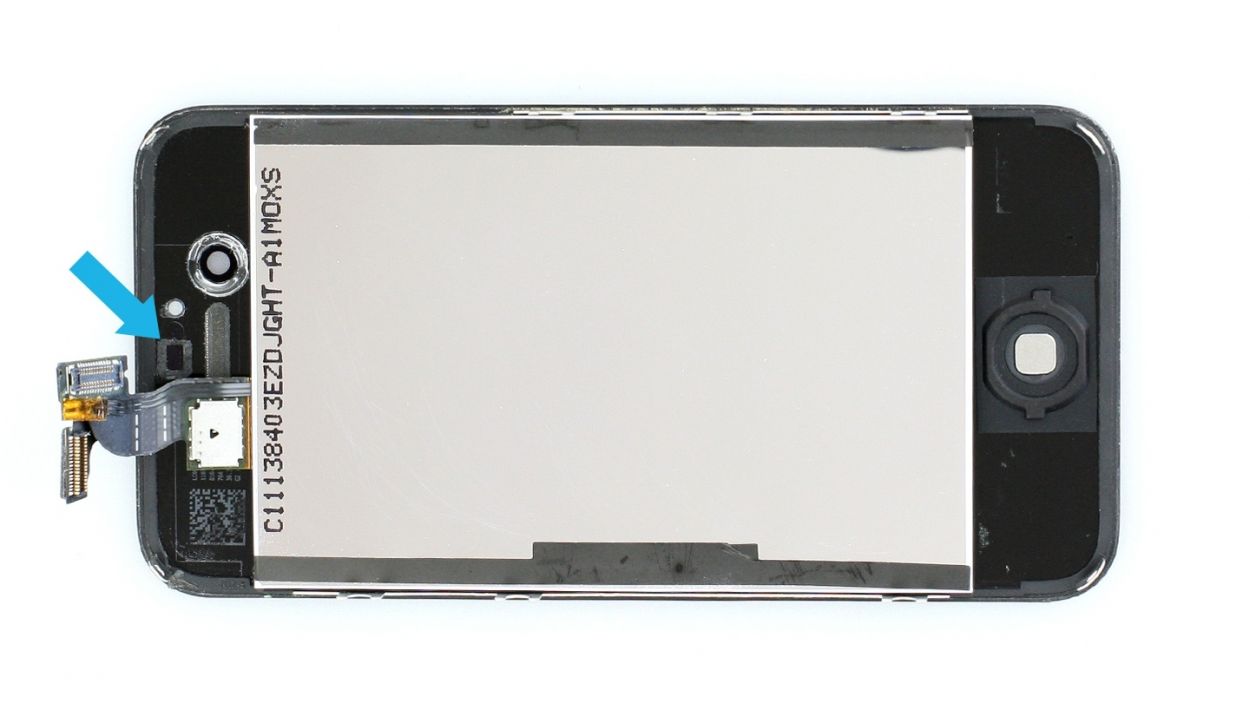
– Using the spudger, work your way around the entire frame once (see figure 3). If the display is still really stuck on, use some more hot air.
– Keep warming it up until you can easily lift the display assembly (see figure 4) and it’s no longer stuck on (please note: The display’s connection cables are on the side with the standby button).
Step 18

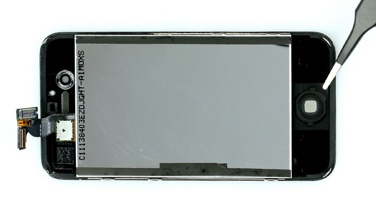
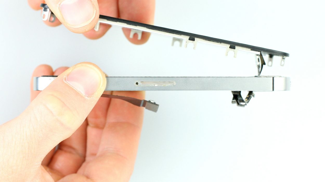
– Pay special attention to the touch and LCD cable when you remove the display.
– Carefully guide this cable through the midplane.
Step 19

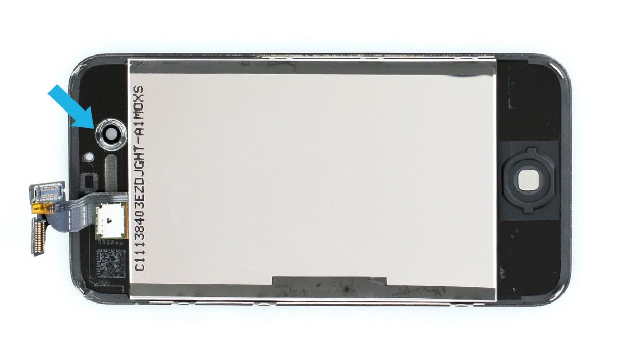
– Not all displays are created equal, so you might need to snag a few parts from your old screen before you dive into the new installation. Here’s what you might need to borrow: the earpiece mesh (which could need a little glue action, check out figure 1), the front camera bracket (see figures 2 and 3), and the frame sticker at the sensor site (see figure 4).
– If you’re taking the earpiece mesh from the old screen, remember it may need some glue to stick on (see figure 1).
– Don’t forget about the front camera bracket! You’ll need it from your old display (see figures 2 and 3).
– Grab the frame sticker from the sensor site as well (see figure 4).
– Time to transfer the Home button! It’s glued to the old screen, so gently peel off the adhesive film using tweezers or a spatula (see figure 5). A little paintbrush can help you dust off the Home button afterward.
– Peel off the protective film on the back of your shiny new LCD.
– If the adhesive film next to the Home button and front camera looks good, you can keep using it. If not, it’s time to say goodbye and pull it off.
Step 20
When you put on the new display, make sure you pull the LCD and touchscreen cables all the way through the slot in the midframe. You have to pull both cables through the slot up to the same length (see figures 1 and 2).
– See if you can press the Home button as usual once the assembly is evenly on the frame. Make sure that the display is properly fitted to the frame (see figure 3).
– Make sure the washers for the six identical Phillips screws are fitted properly (see figure 4). (The display’s clips should be between the washer and the frame.)
Step 21

– Now you have to tighten the six identical Phillips screws (three on each side).6 x 1.5 mm Phillips screws
Step 22
– Fasten all four identical Phillips screws again.3 x 1.6 mm Phillips screws1 x 1.6 mm Phillips screw
– Don’t forget to put the little black sticker back on the screw.
Step 23
– Put the speaker back in.
– At first, only tighten the two Phillips screws on the speaker a little bit (see figure 1).1 x 2.4 mm Phillips screw1 x 2.4 mm Phillips screw
– The speaker’s clips have to be against the speaker behind the higher level of the middle cover (see figure 2). This is easiest if you only slightly screw in the speaker at first so it can still move around a little.
– Once the clips are fitted properly, you can tighten the screws.
Step 24
– Now put the vibration motor in the appropriate position.
– The old glue is usually enough to hold it, but if the vibration motor is too loose, use new glue. If it’s not securely attached, your phone’s vibration will be weaker.
Step 25


– First, pop that rubber protector back onto the sharp edge of the logic board. Remember, the thicker side should be facing down (check out figure 1 for a visual).
– Next, gently place the logic board back in its cozy spot, just like in the picture (figure 2). You might need to try a couple of times until you hear a satisfying click when it’s snug in place. Use figure 3 to double-check that your logic board is sitting pretty. Also, make sure that the antenna cable attached to the speaker isn’t hiding under the logic board.
– Finally, let’s secure everything! Grab your trusty Phillips screwdriver and fasten all four screws that hold the logic board in place (see figure 3). Here’s what you’ll be using: 1 x 4.9 mm Phillips/flathead screw, 1 x 2.4 mm Phillips screw, 1 x 2.6 mm Phillips screw, and 1 x 3.7 mm Phillips/flathead screw.
Step 26


– Connect the antenna connector (see figure 1).
– Put on the cover for the antenna cable (see figure 2).
– Fasten the Phillips screw on the antenna cover (see figure 3).1 x 1.5 mm Phillips screw
Step 27
Don’t pull too hard on the cable if it’s too short because it could easily tear. We recommend that you reinstall the display.
– Reconnect all five contacts. Use your finger to carefully press them in. Only use as much pressure as you need for the contacts to gently click into place.
– If the LCD cable is too short, you forgot to pull it tightly through the slot in the midframe.Don’t pull too hard on the cable if it’s too short because it could easily tear. We recommend that you reinstall the display.
Step 28
– Put the copper contact back in as shown in the picture (see figure 1).
– Then tighten the Phillips screw in the thread again (see figure 2).1 x 2.6 mm Phillips screw
– Use tweezers or the laboratory spatula to put on the black sticker (see figure 3).
– Connect the camera connector.
Step 29


– Carefully put on the cover. It will be slightly clamped in place (see figure 1).
– Fasten all the Phillips screws on the connector cover (see figure 2):1 x 2.6 mm Phillips screw2 x 1.2 mm Phillips screws1 x 2.7 mm Phillips screw (thin thread)
Step 30

– Connect the dock connection cable again and put the silver cover on it.
– Fasten the two Phillips screws for the dock connection cable.1 x 1.1 mm Phillips screw1 x 1.4 mm Phillips screw
Step 31

– Give that plastic tab a little love! Either pull it off if it’s being a rebel, or gently tuck it back in if you took it out. It’s all about keeping things tidy during your repair adventure!
Step 32


– Now put the battery back in the iPhone.
– First you have to attach the antenna connector again (see figure 1).
– Then install the antenna cover (see figure 2).
– Now click the battery connector back into place and screw it in (see figure 3).1 x 1.5 mm Phillips screw1 x 1.3 mm Phillips screw
Step 33
– Put the back cover back on and carefully push it the last few millimeters toward the dock connector.
Step 34

– Now screw in the two screws at the bottom of the enclosure.2 x 3.6 mm pentalobe screws
– Then all you have to do is push in the SIM card tray.
Step 35

When the battery is removed from the device, the iPhone loses the time and sets itself to 1:00 a.m. on 1/1/1970. You could have trouble connecting to the cellular network if the time isn’t set.
– Synchronize your iPhone with iTunes or connect to a WLAN network and wait until the time is set.
– Remove the SIM tray with the SIM card and reinsert it.
– Activate airplane mode on the device and then deactivate airplane mode.