DIY Guide to Replace iPhone 7 Back Cover Tutorial
Duration: 120 min.
Steps: 45 Steps
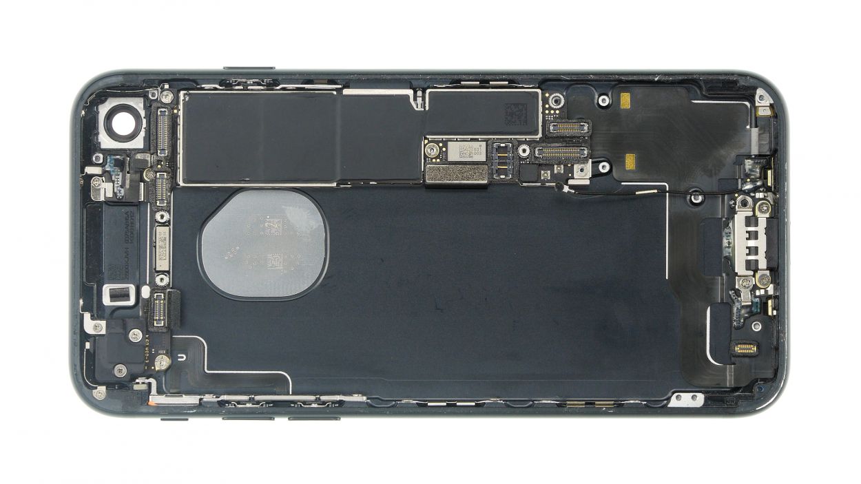
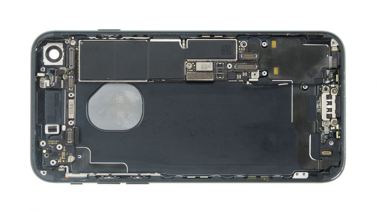
Whether your iPhone 7’s back cover has seen better days or you’re just itching for a fresh vibe, this handy guide is here to help you swap it out like a pro! You’ll be able to tackle this task solo and give your device a snazzy new look. Don’t forget, you can snag the perfect iPhone tool kit from our online store. Good luck on your back cover adventure!
Step 1
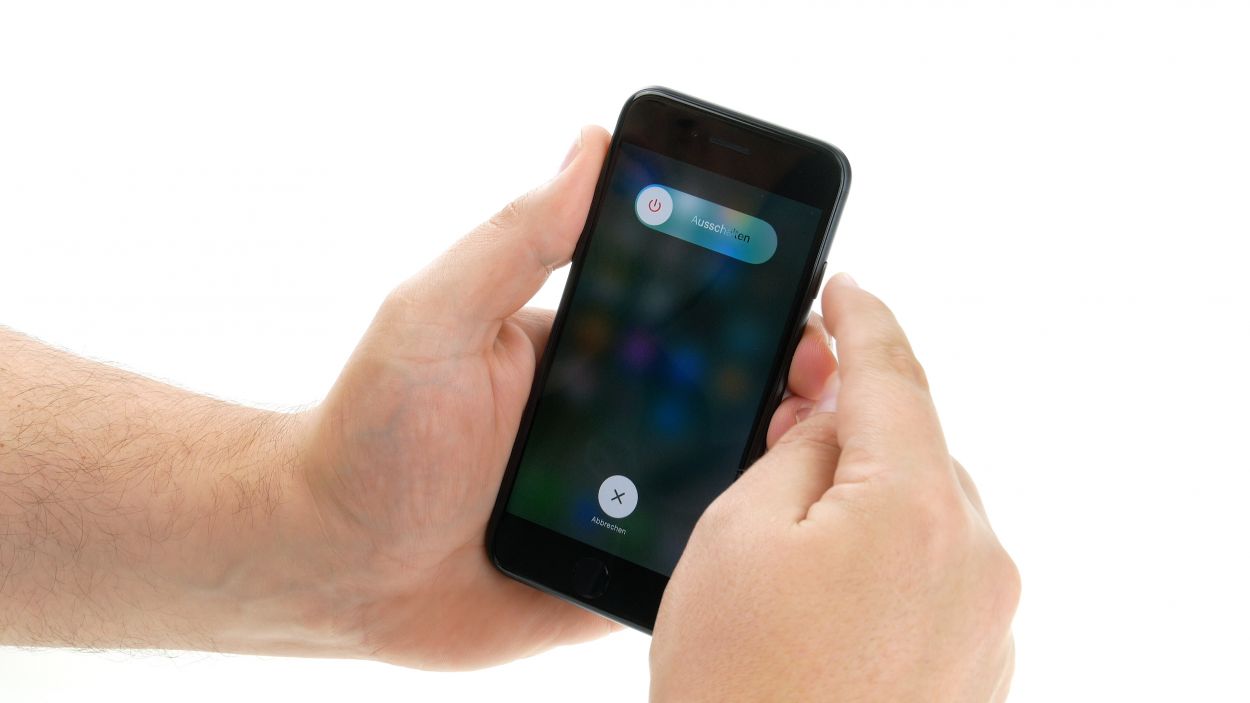
– To keep your device safe from any pesky short circuits while you’re on your repair journey, make sure to power it down completely first.
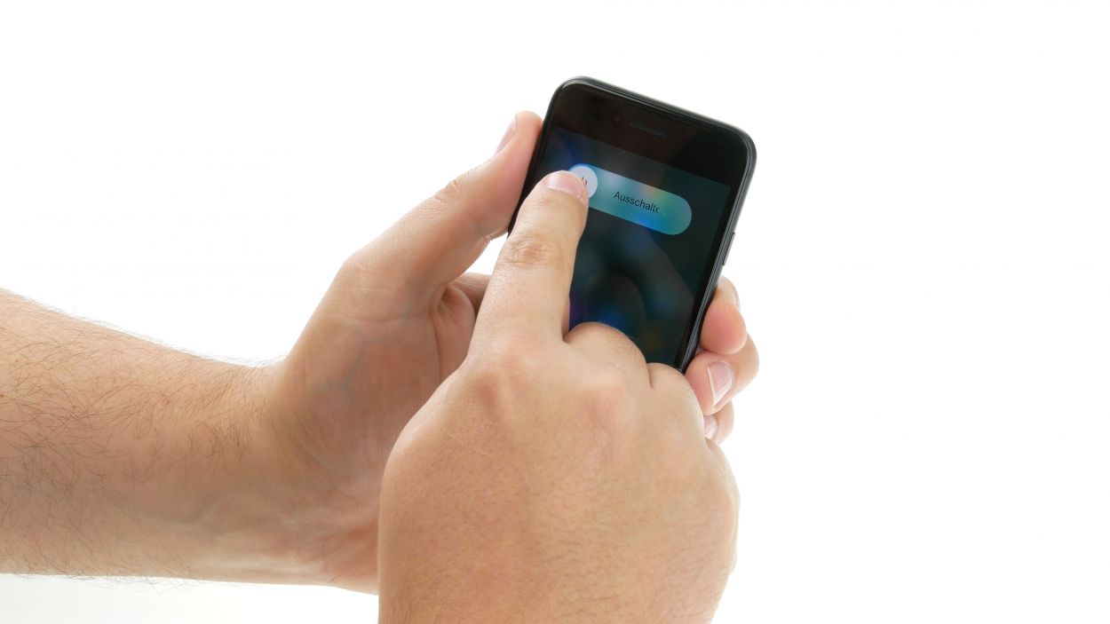
– Give the sleep/wake button a good press until the ‘Switch off’ slider pops up on your screen.
– Swipe that slider from left to right like a pro.
– In just about ten seconds, your iPhone will be completely off and ready for your repair magic!
Step 2
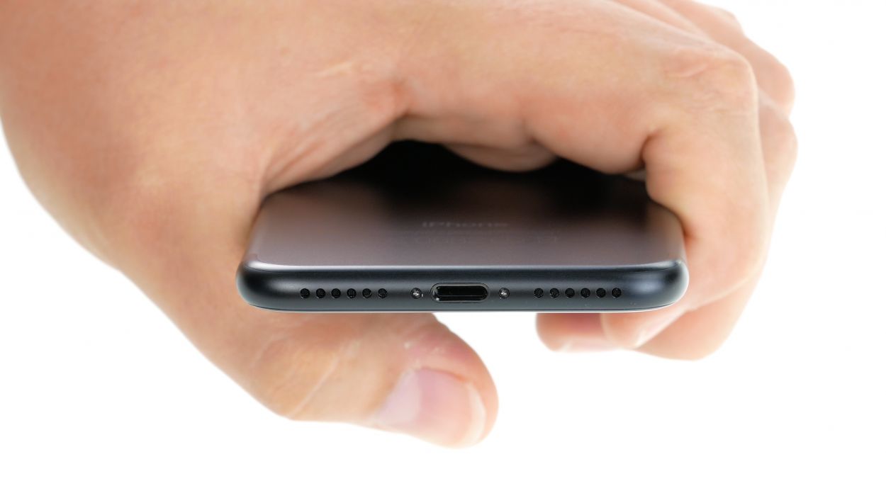
2 × 3,3 mm Pentalobe
To keep your little screws and parts from going on a wild adventure, we suggest using a screw storage solution. An old sewing box works like a charm! Here at Salvation Repair, we prefer a nifty magnetic mat where we can arrange the parts just like they were in the phone. It’s like a puzzle, but with less frustration!
– Grab your trusty Pentalobe screwdriver and let’s unscrew those two Pentalobe screws hanging out to the left and right of the Lightning connector.
– Once you’ve got those screws loose, pop them into a screw storage solution so they don’t wander off on their own adventure!
Step 3
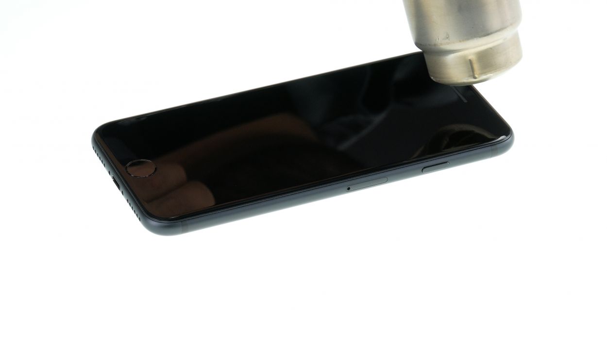
When heating your device, aim for a cozy warmth—just enough to keep it touch-friendly without turning your fingers into crispy critters!
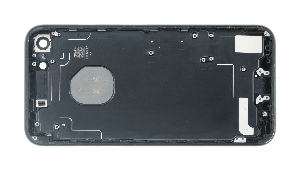
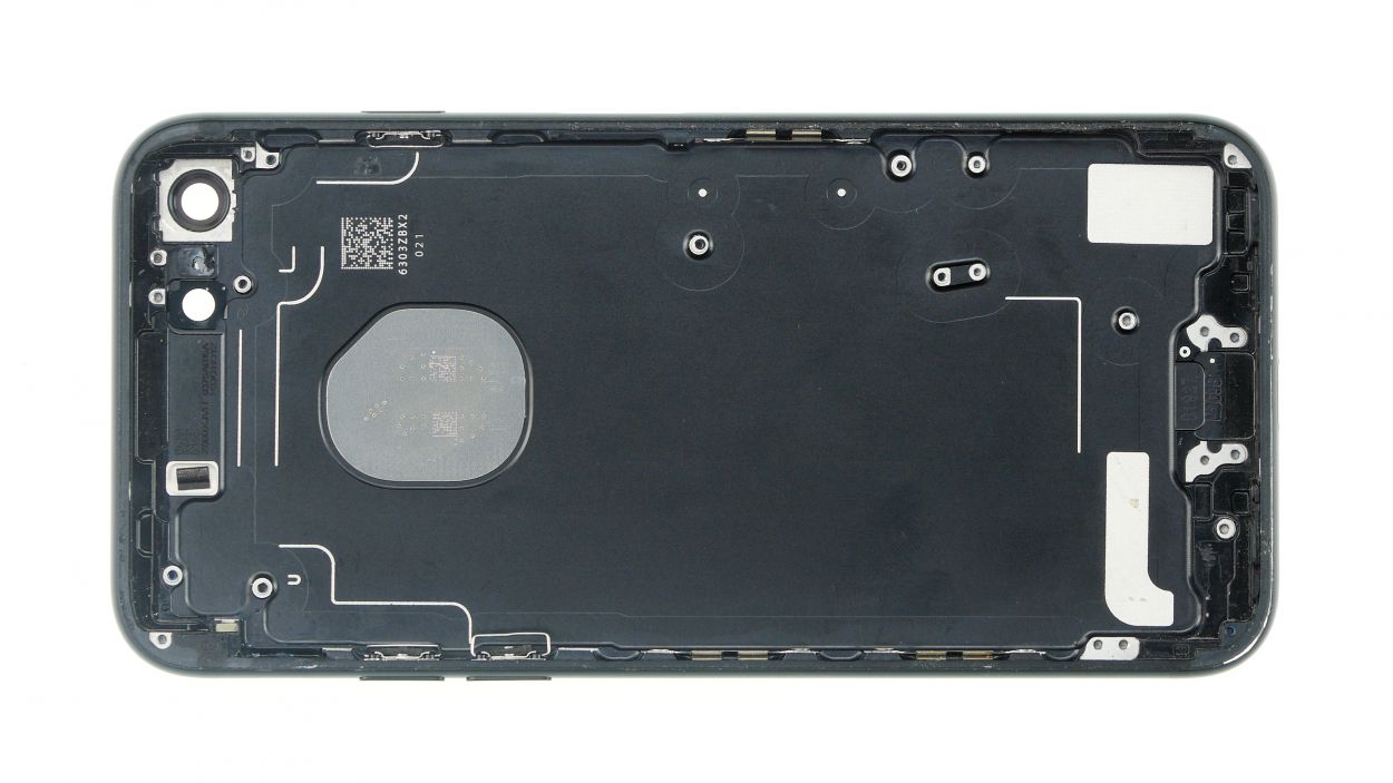
– First, set your iPhone 7 down on a clean, soft surface. This will keep the back cover looking fresh and scratch-free!
– Grab your trusty hot air tool, whether it’s a heat gun or a regular hairdryer, and gently wave it over the edge of the screen. This will warm up the adhesive and make your repair journey a breeze.
Tools Used
- heat gun to heat parts that are glued on so they’re easier to remove.
In most cases, you can also use a hairdryer.” rel=”noopener”>Heat gun
Step 4
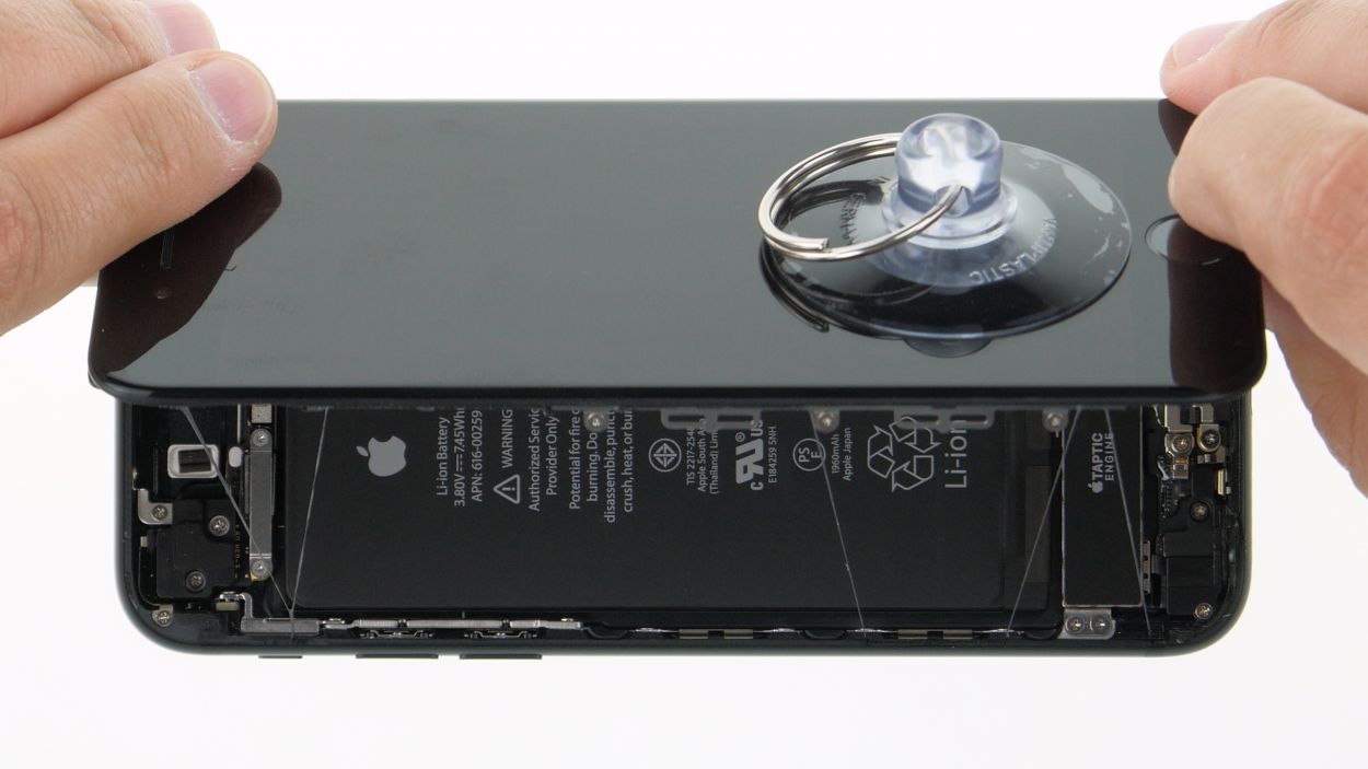
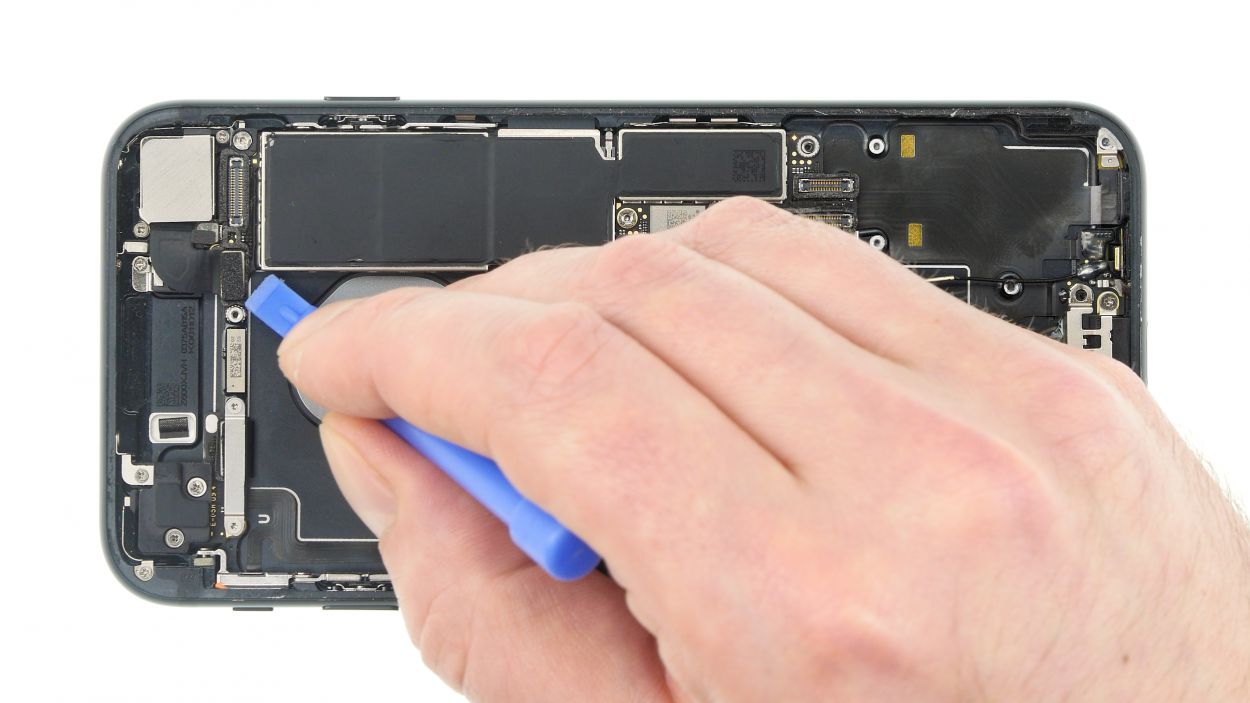
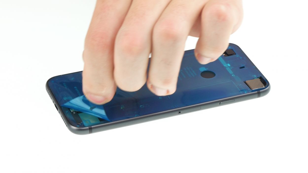
Opening up your iPhone 7 means saying goodbye to its dust, splash, and waterproof warranty. But hey, you’re on a repair adventure now!
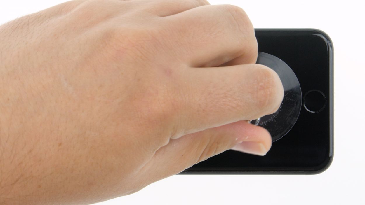
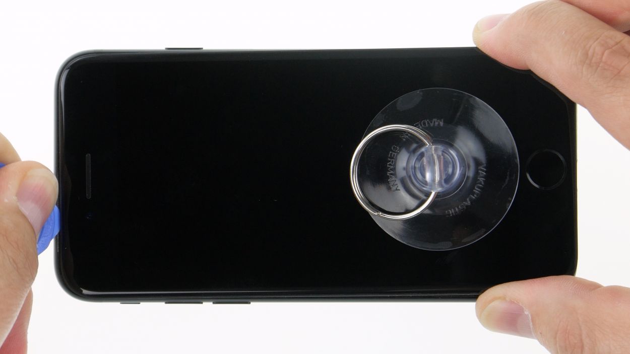
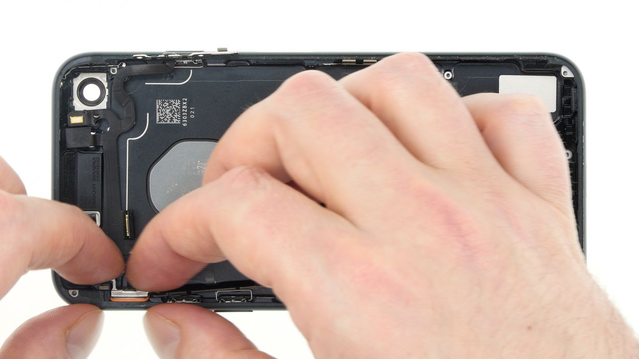
– Once you’ve warmed up the edges of the display, grab a suction cup and pop it right on the display near the home button.
– Give that suction cup a good pull to create a slim gap between the aluminum frame and the display.
– While you’re at it, slide a flat, sturdy tool into that gap. A hard plastic plectrum works like a charm!
– Now, let’s make that gap a bit bigger by gently pushing down on the aluminum frame with your tool.
Tools Used
Step 5
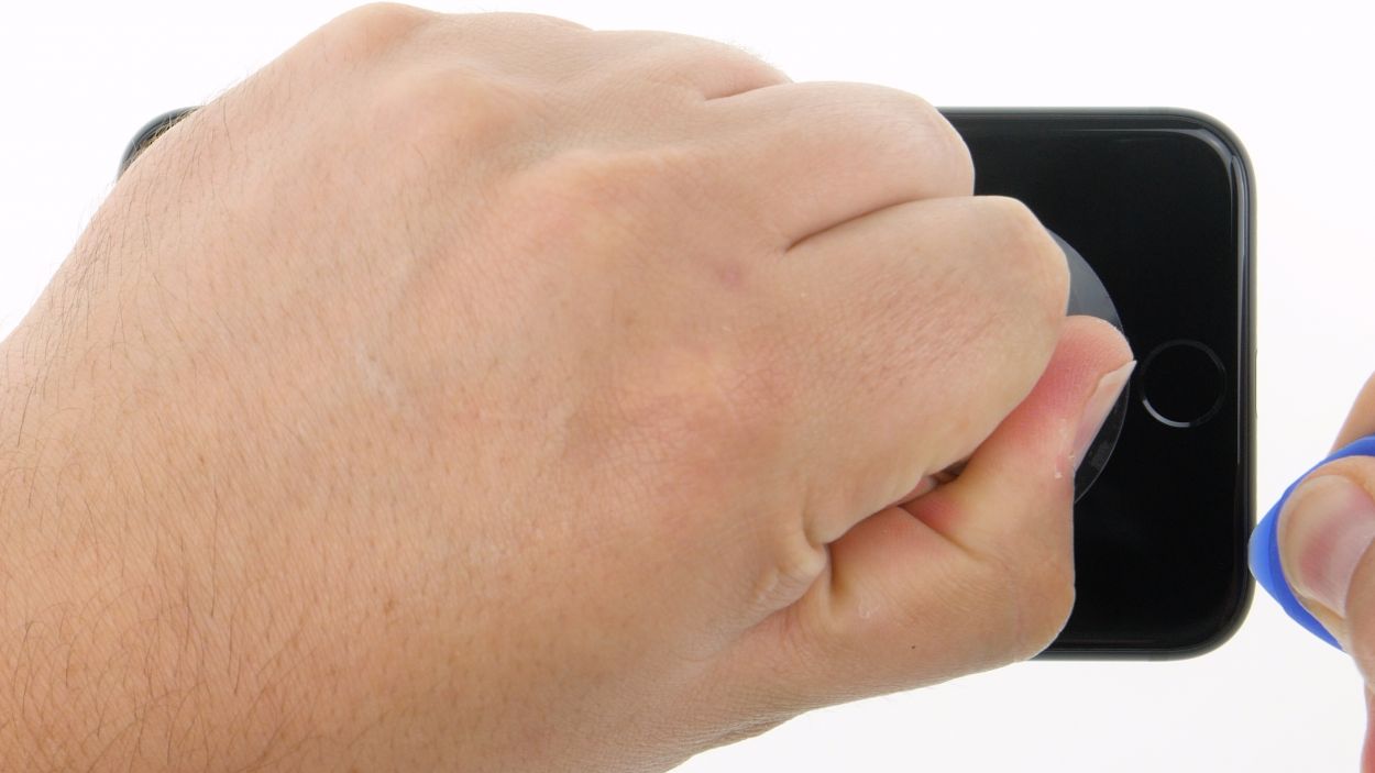
Hey there! Just a friendly reminder: when you’re using those picks, make sure not to push them too far near the sleep/wake button. We want to keep that flex cable of the display safe and sound!
Tools Used
- heat gun to heat parts that are glued on so they’re easier to remove.
In most cases, you can also use a hairdryer.” rel=”noopener”>Heat gun - Pick Set
- Flat Picks
Step 6

1 × 2,4 mm Y-Type
3 × 1,0 mm Y-Type
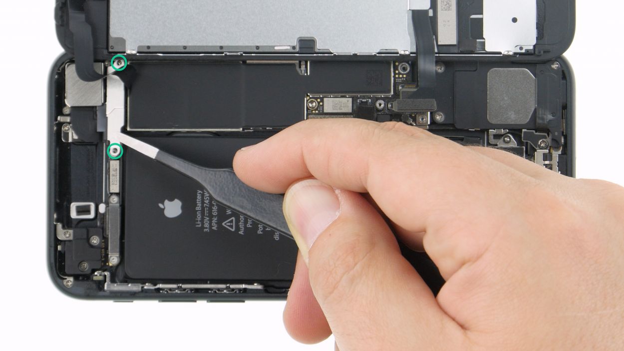
Battery connector
At the start of your repair journey, give that battery connector a little love and loosen it up! This nifty move will help dodge any potential short circuits and keep your iPhone 7 from accidentally waking up while you’re in the zone.
– Grab your trusty Y-type screwdriver and loosen those four Y-type screws like a boss! Once they’re all loosey-goosey, gently lift off the bracket plate that’s hanging out over the battery connector.
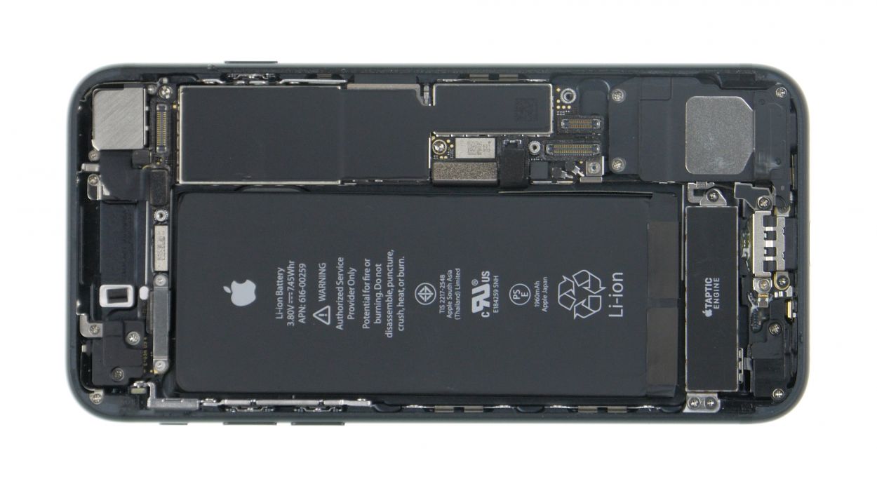
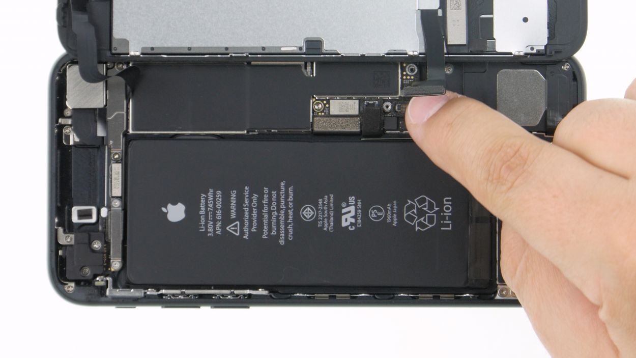
Step 7
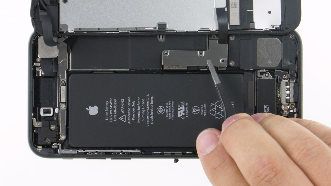
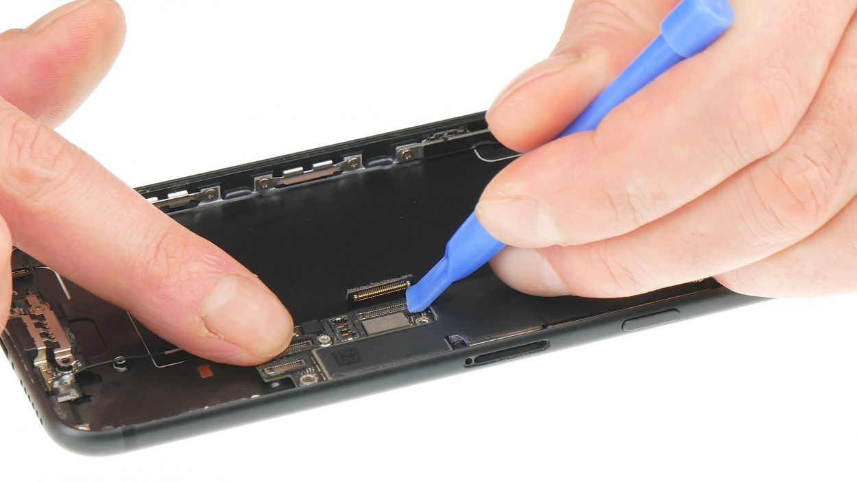
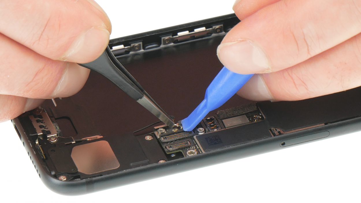
Display connector
Home button connector
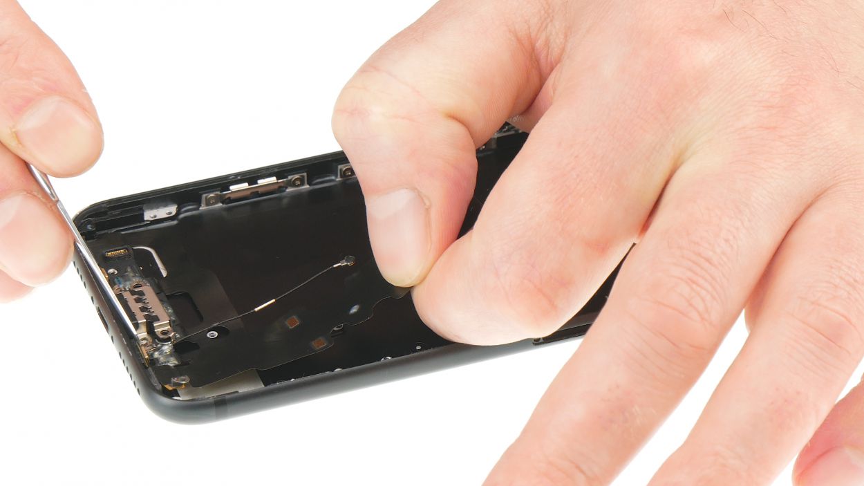
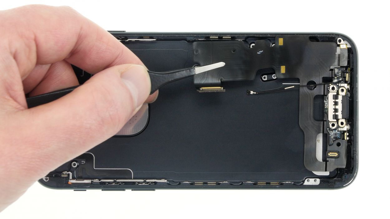
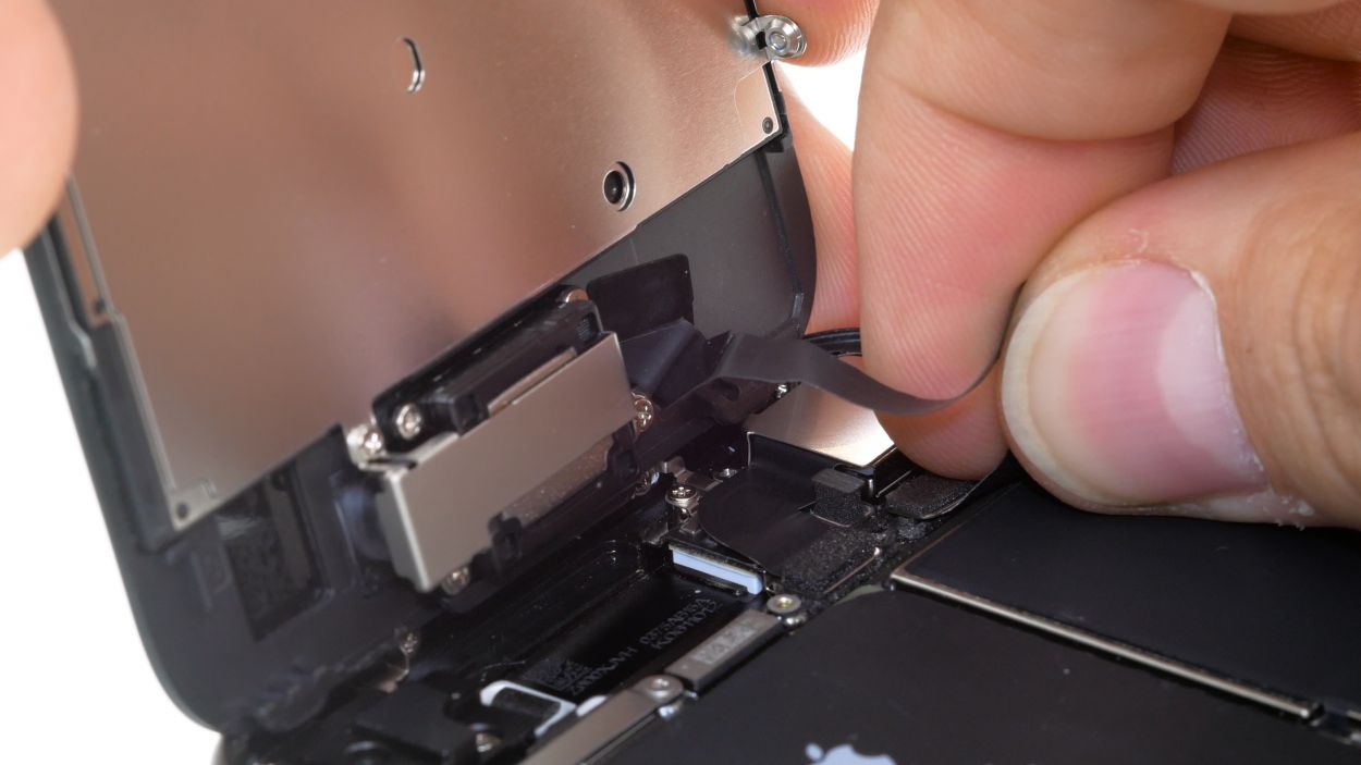
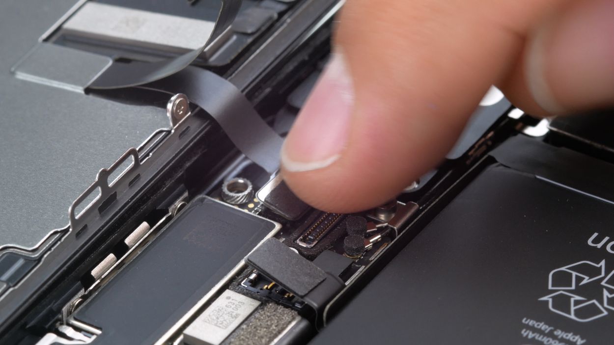
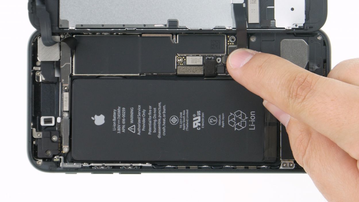
When you’re popping off those display connectors, remember to start from the side that’s free of tiny components. It’s like giving your device a gentle hug, keeping it safe from any accidental oopsies!
– Now, with your trusty plastic spudger in hand, gently separate those two display connectors (the display and the home button) just like you did before. You’ve got this!
Tools Used
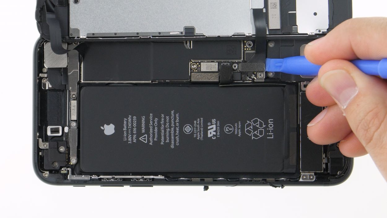
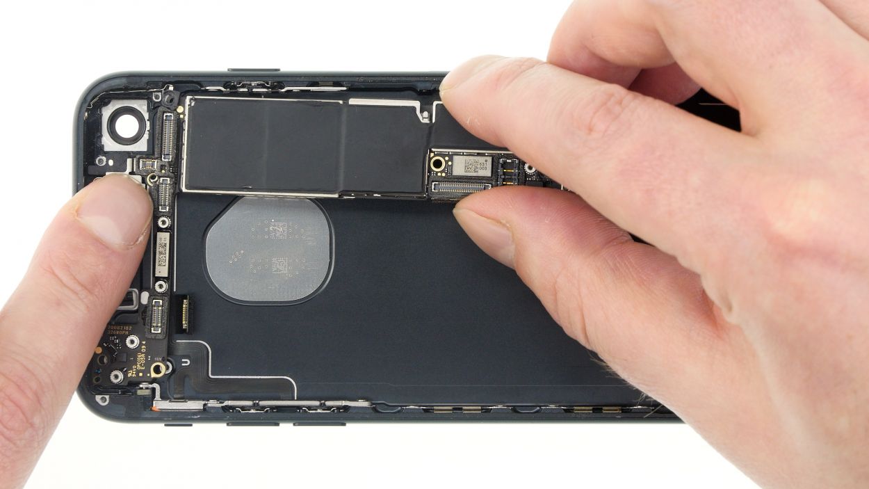
Step 8
2 × 1,2 mm Phillips
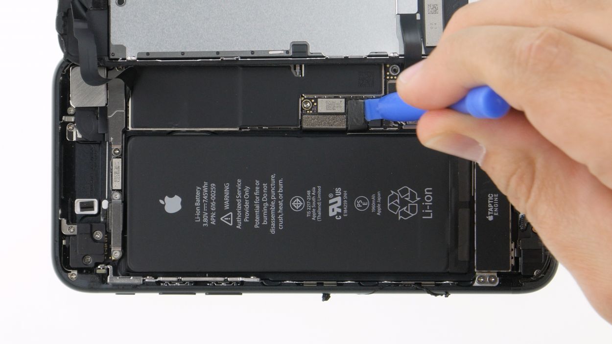
FaceTime connector
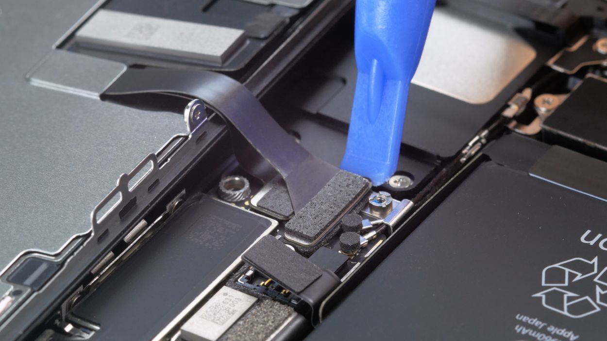
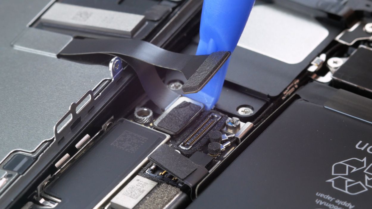
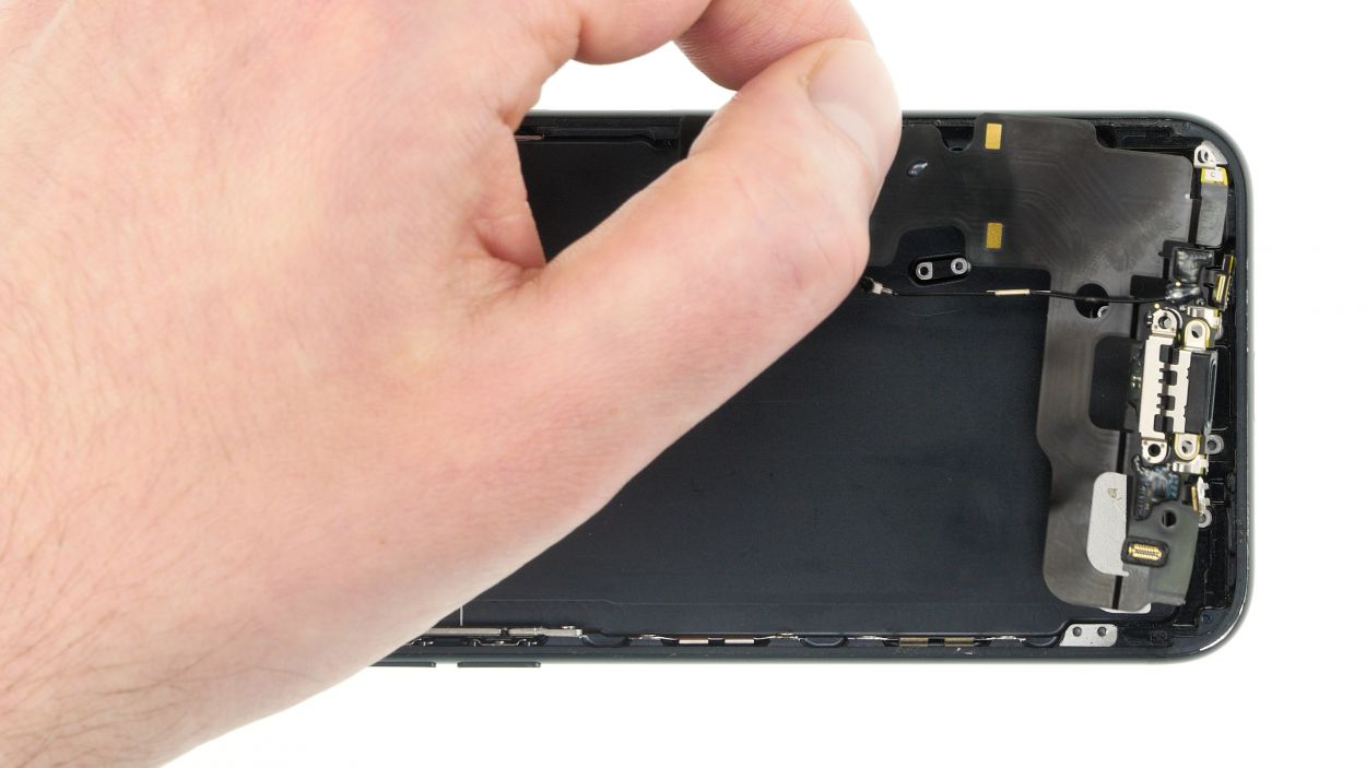
When you’re about to detach the FaceTime connector, start from the side that’s free of tiny components on the board. It’s like giving your device a gentle nudge while keeping it safe from any potential mishaps!
– In the first step, remove the two Phillips screws fixing the bracket plate over the FaceTime connector and take it out.
Step 9

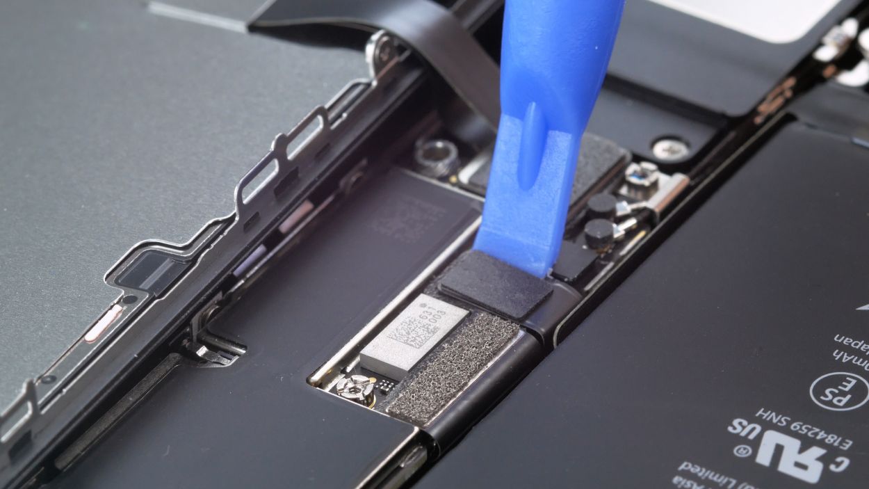
When you’re carefully prying those connectors apart, remember to start from the side that’s free of tiny components on the board. It’s like giving your device a gentle nudge while keeping it safe from any potential mishaps!
– Time to grab that trusty Phillips screwdriver and get to work! Unscrew those two Phillips screws from the plastic cover and gently lift it off. You’re doing great!
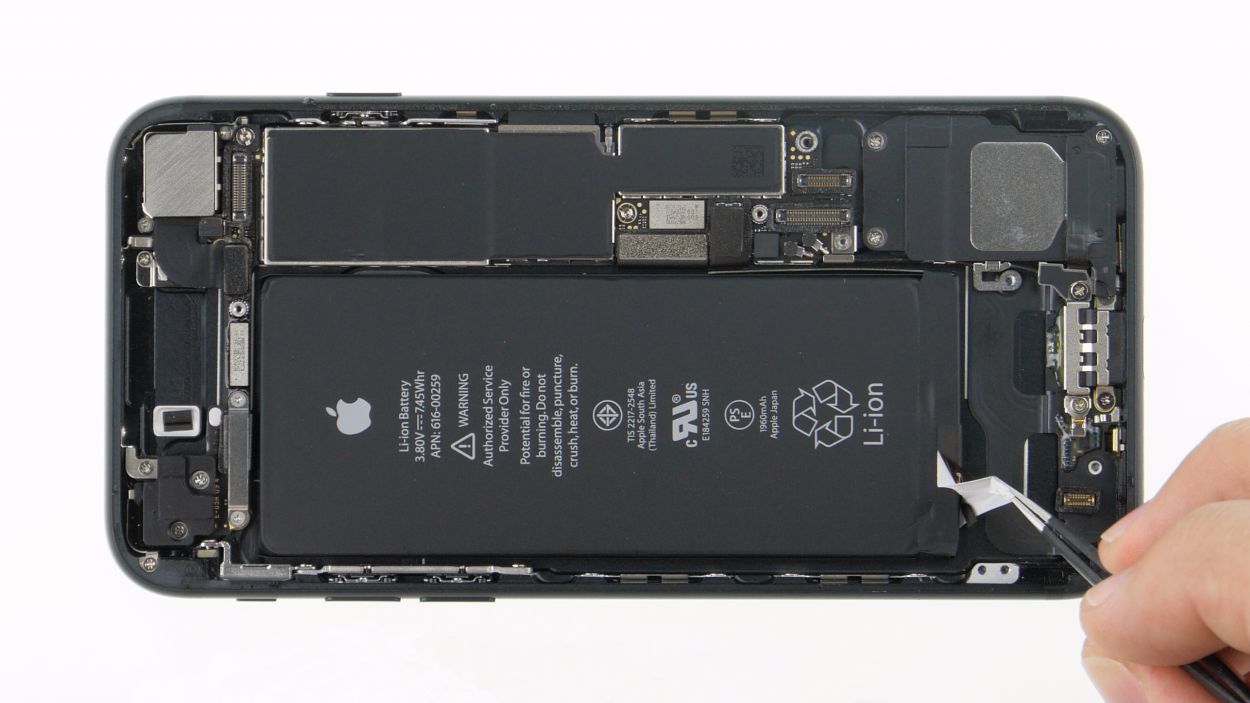

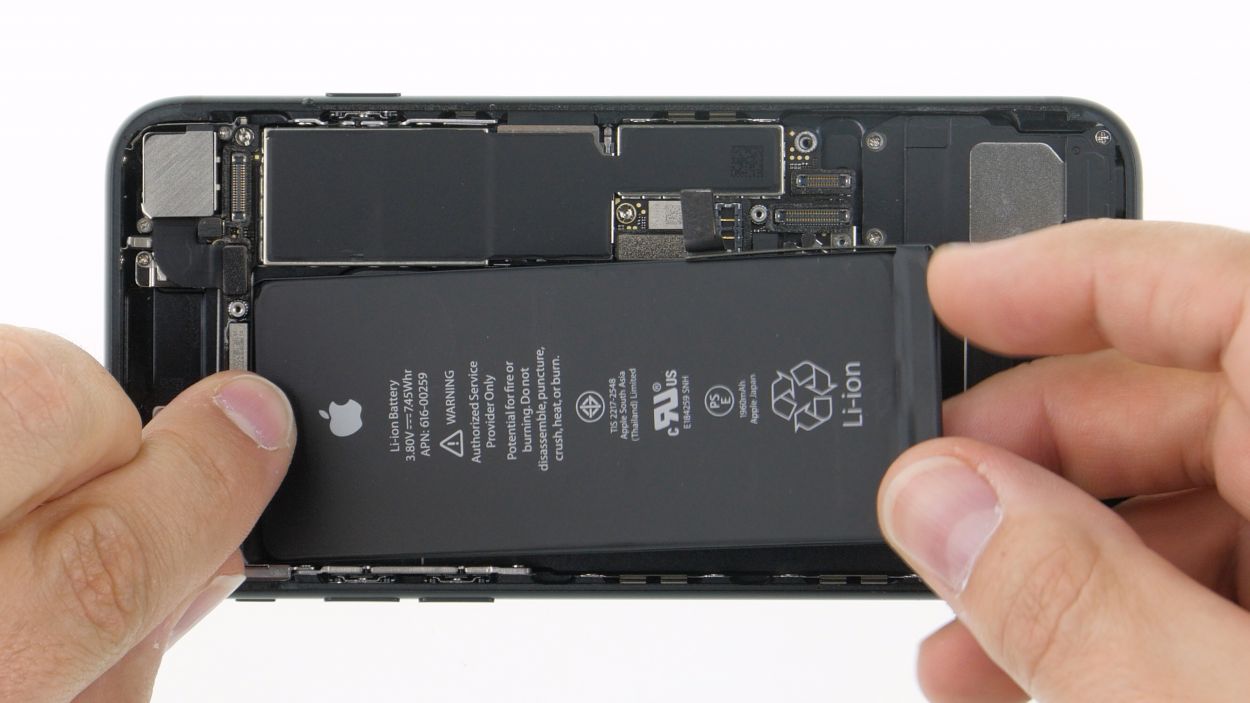
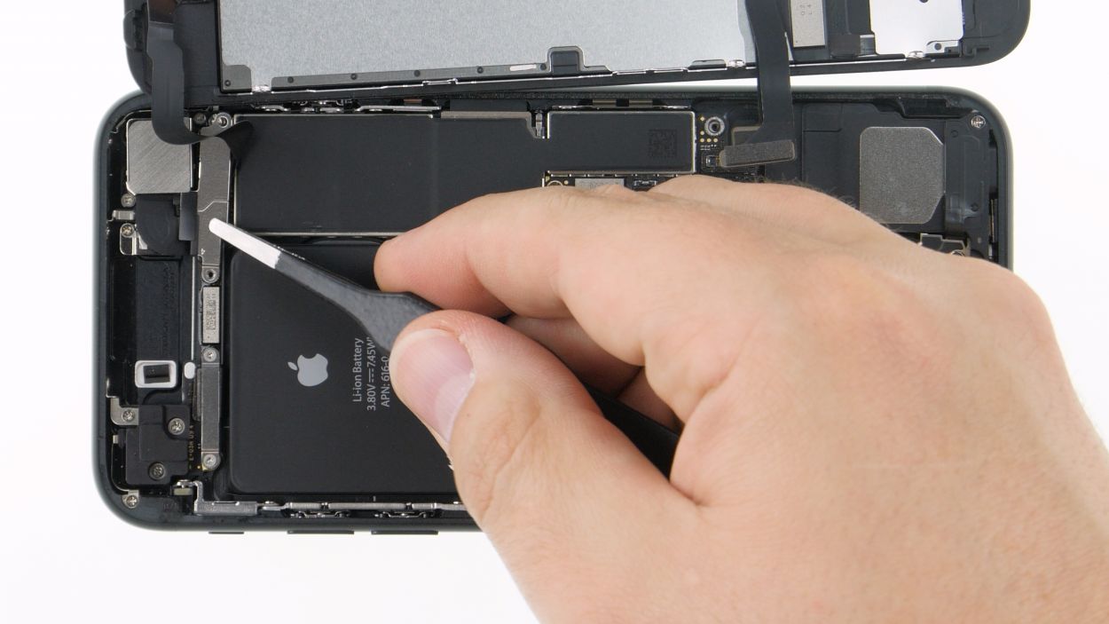
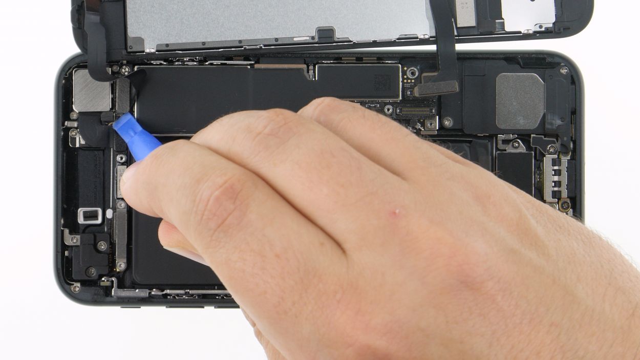
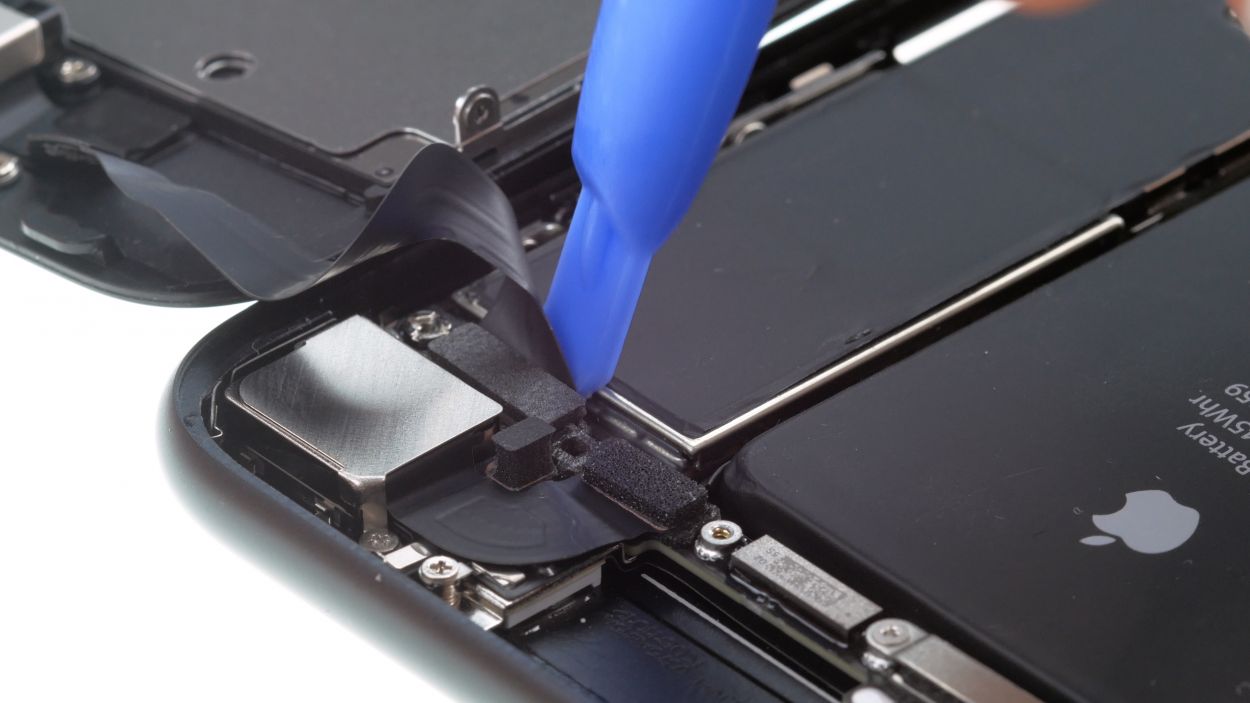
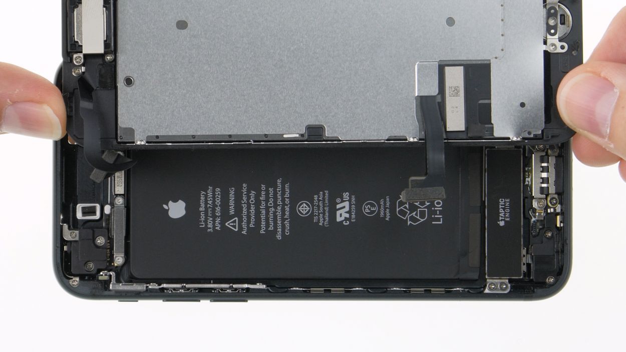
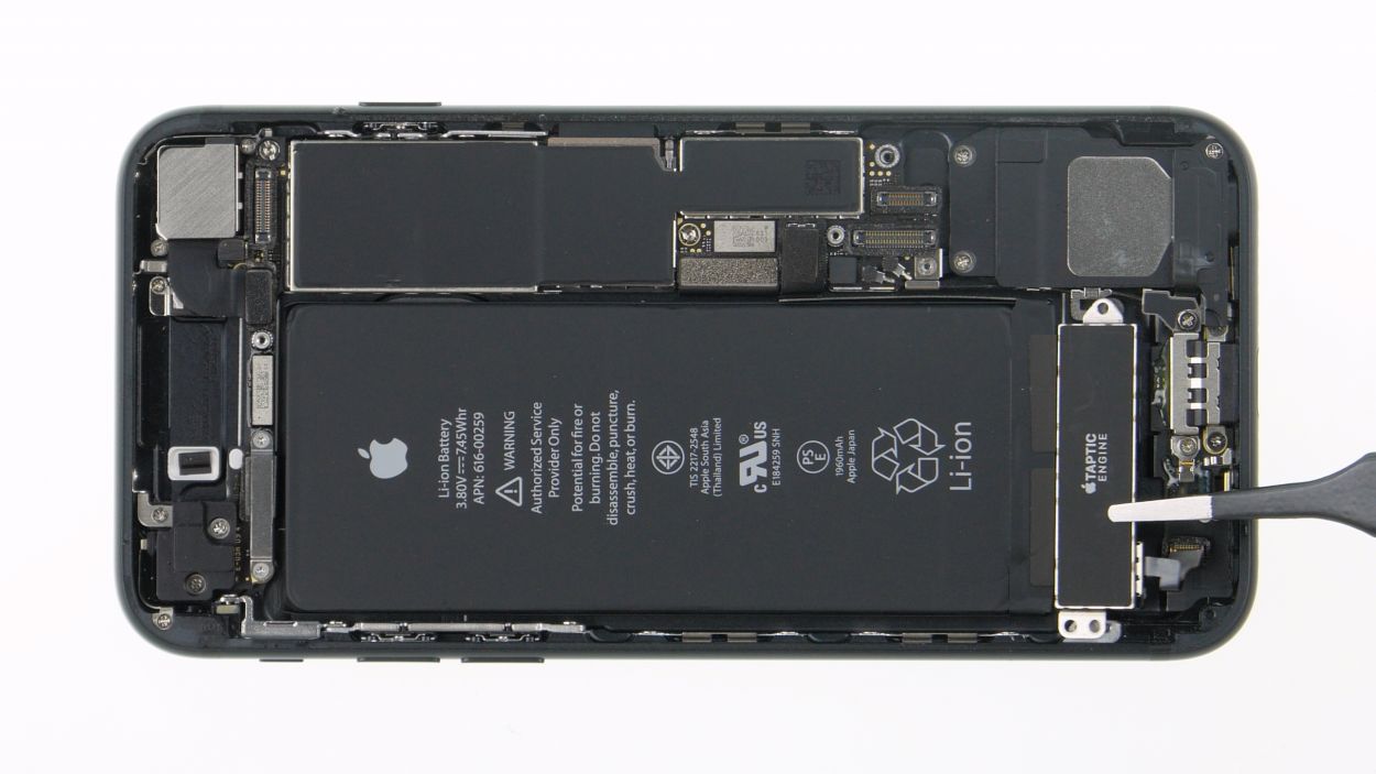
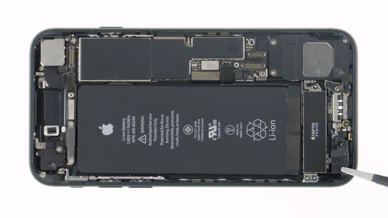
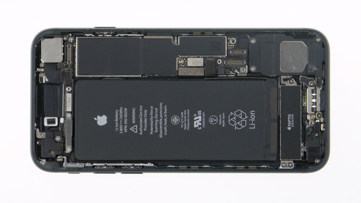
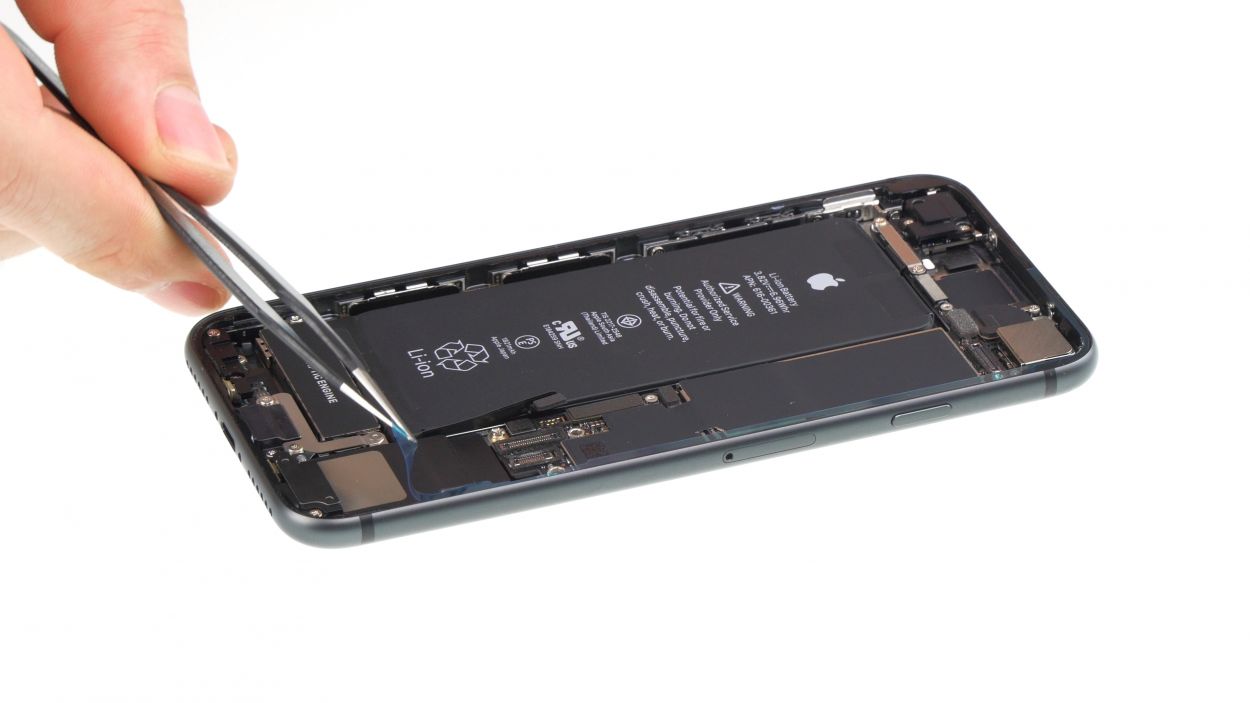
When you’re pulling out those adhesive+strips+iPhone+7&crid=1TJIMMAJSUJUZ&sprefix=repair+tools%2Caps%2C165&linkCode=ll2&tag=salvationrepa-20&linkId=c486487cf454ce8edd6f5beefab4110f&language=en_US&ref_=as_li_ss_tl’>adhesive strips, keep them as flat as a pancake to avoid any tearing mishaps! And make sure to hold onto the battery and your iPhone like they’re your best buddies, especially when you’re yanking out that last piece of tape. We don’t want the battery taking a tumble out of the device!
Tools Used
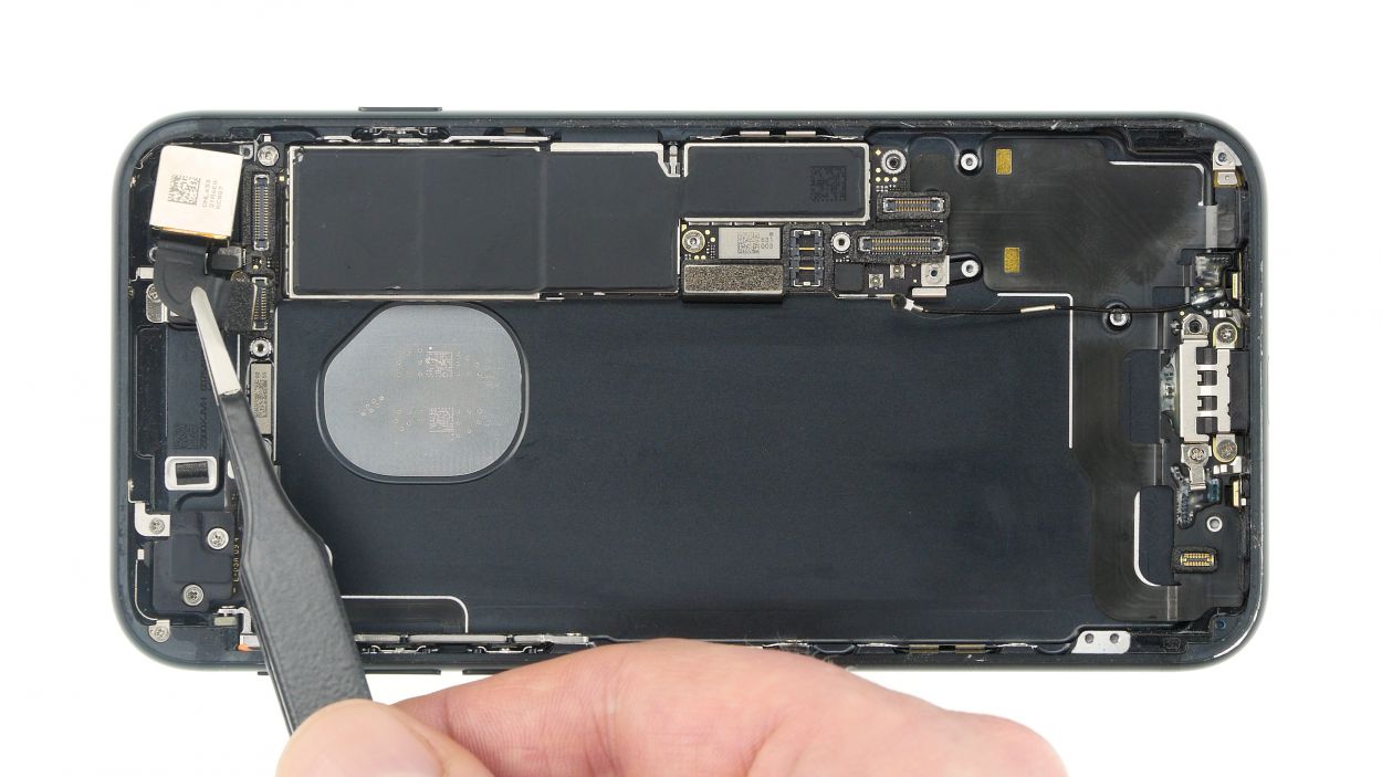
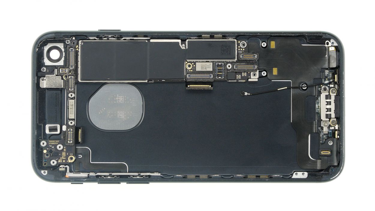
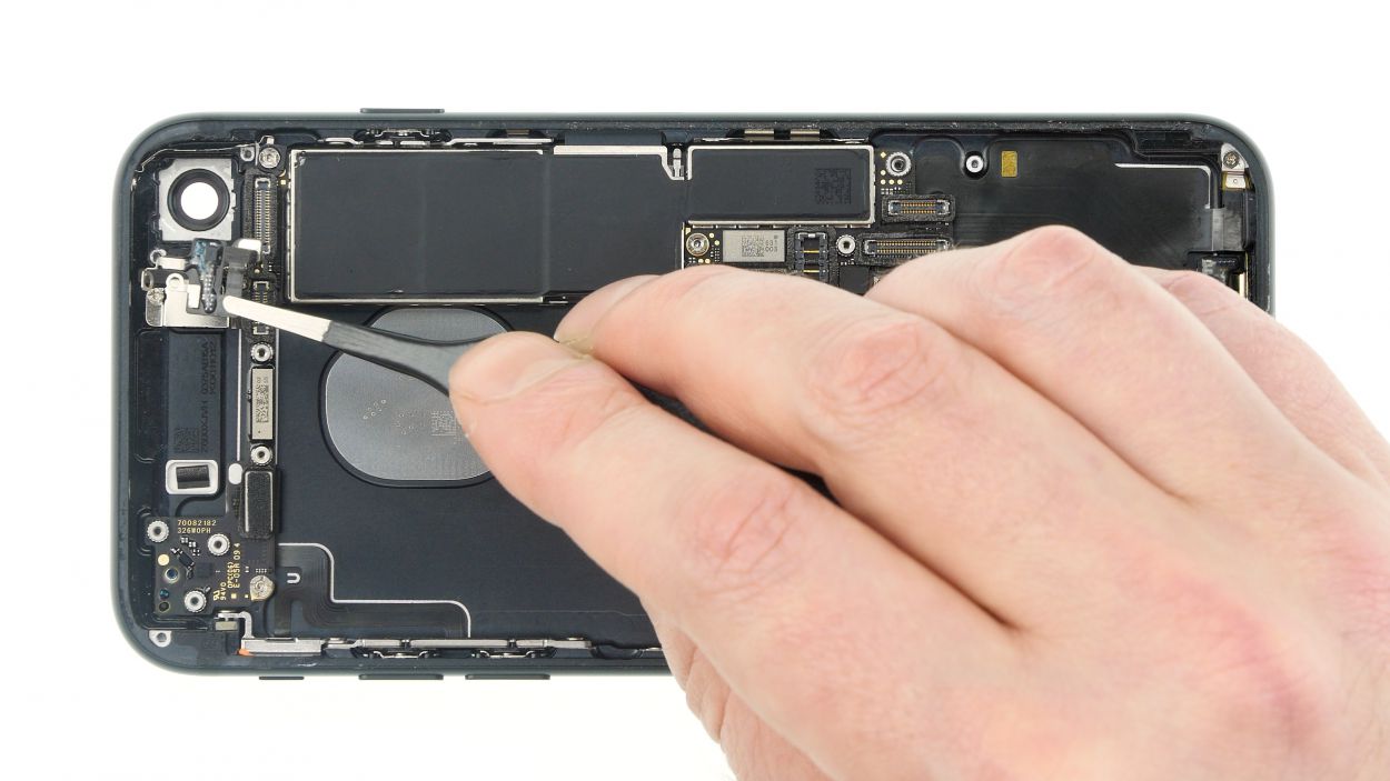
Step 11

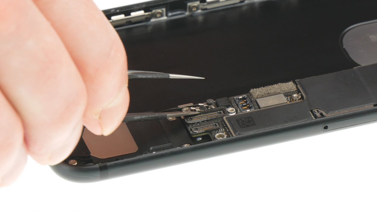
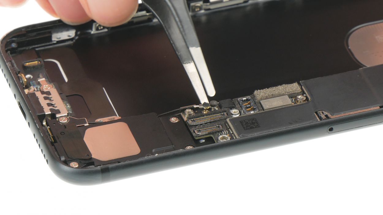
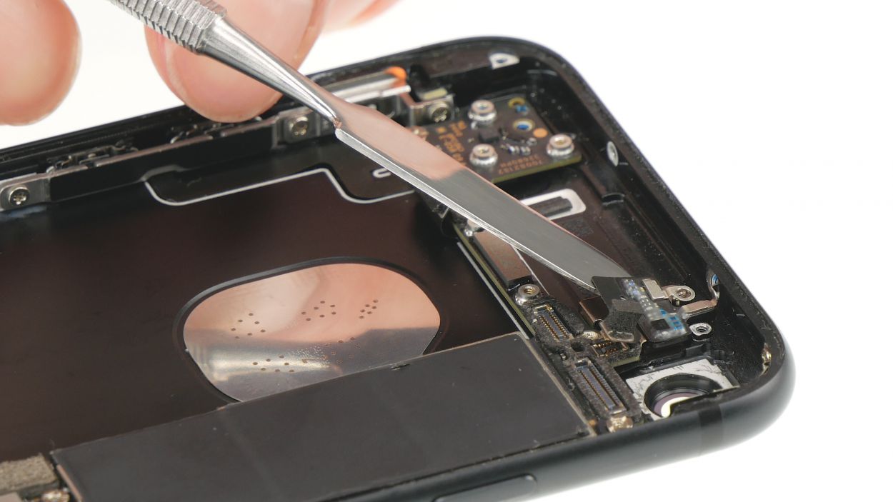
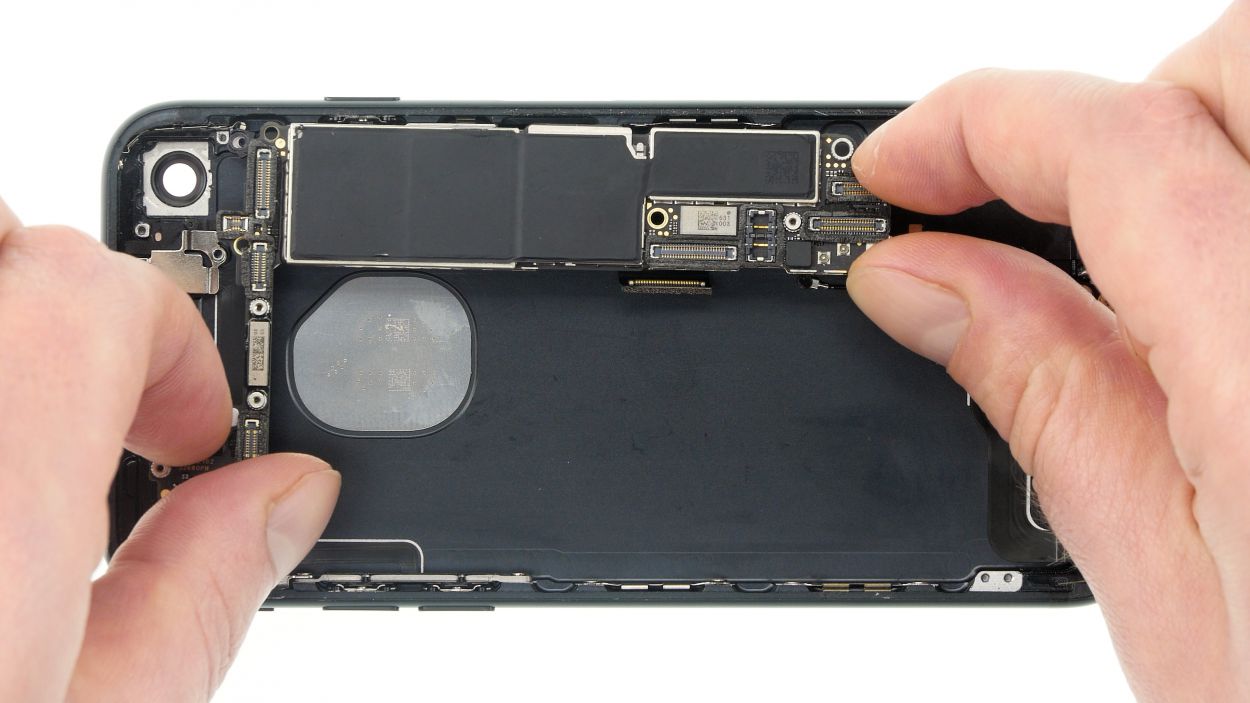
When you’re popping off those antenna connectors, make sure to start from the side that’s free of tiny components on the board. It’s all about keeping your device safe and sound while you work your magic!
– Gently unclip the connectors of both antenna cables from the logic board using a spudger or tweezers—easy does it!
– Next, grab your Phillips screwdriver and unscrew the four screws that keep the speaker snug in its spot.
– With those screws out of the way, you can now lift out the speaker along with the antenna cable. You’re on a roll!
Step 12
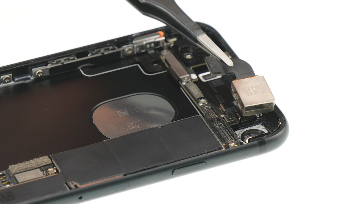
Camera connector
1 × 2,3 mm Phillips
1 × 1,3 mm Phillips
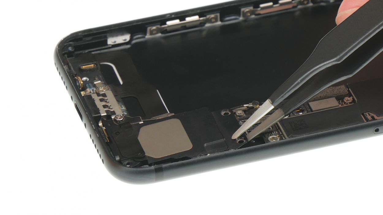
When you’re unhooking that camera connector lever, aim for the side without the tiny components. It’s like giving your device a gentle high five—keeping it safe from any potential boo-boos!
– Gently pop off the iSight camera connector using your spudger—think of it as giving it a little nudge to say goodbye!
– Unscrew those two Phillips screws holding the cover plate above the camera and lift it out of the case like a pro.
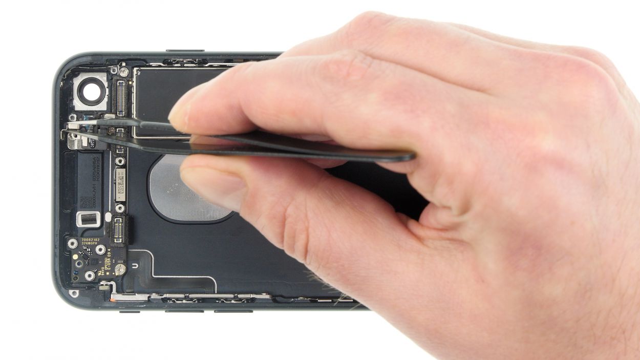
– Now, grab your tweezers and carefully lift the camera from its cozy spot in the rear case. You’ve got this!
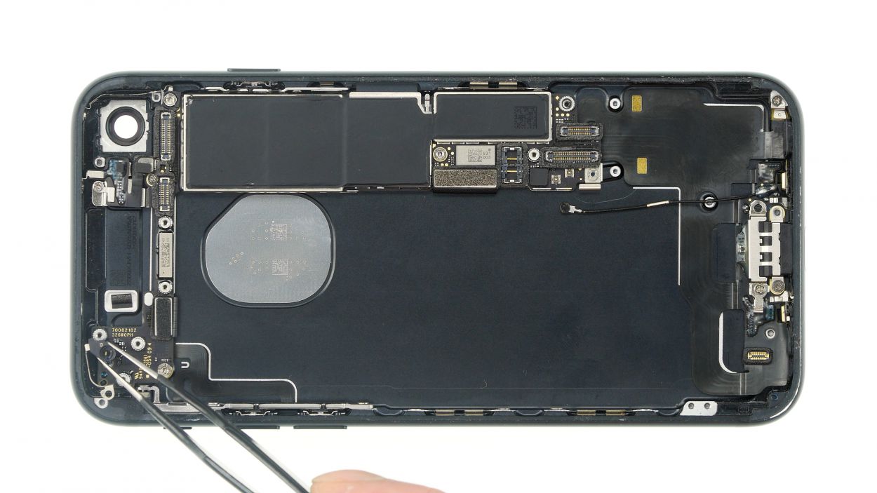
Step 13
2 × 1,1 mm Y-Type
Volume control cable connector
When you’re popping off the volume control cable connector, remember to gently lift from the side without the tiny components. It’s like giving your device a little love tap to keep it safe and sound!
– First, let’s get those two Y-type screws on the silver cover plate loosened up!
Step 14

1 × 1,6 mm Phillips
3 × 1,1 mm Phillips
1 × 2,1 mm Phillips
1 × 1,3 mm Phillips
Just a heads up—one of those sneaky screws is cozying up to the side of the back cover. Keep an eye out for it while you’re on your repair quest!
– First, let’s tackle those four Phillips screws holding the antenna cover in place. Unscrew them like a pro and gently lift off the cover. You’ve got this!
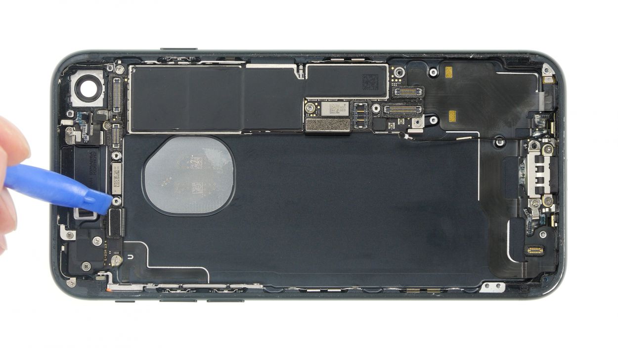
Step 15
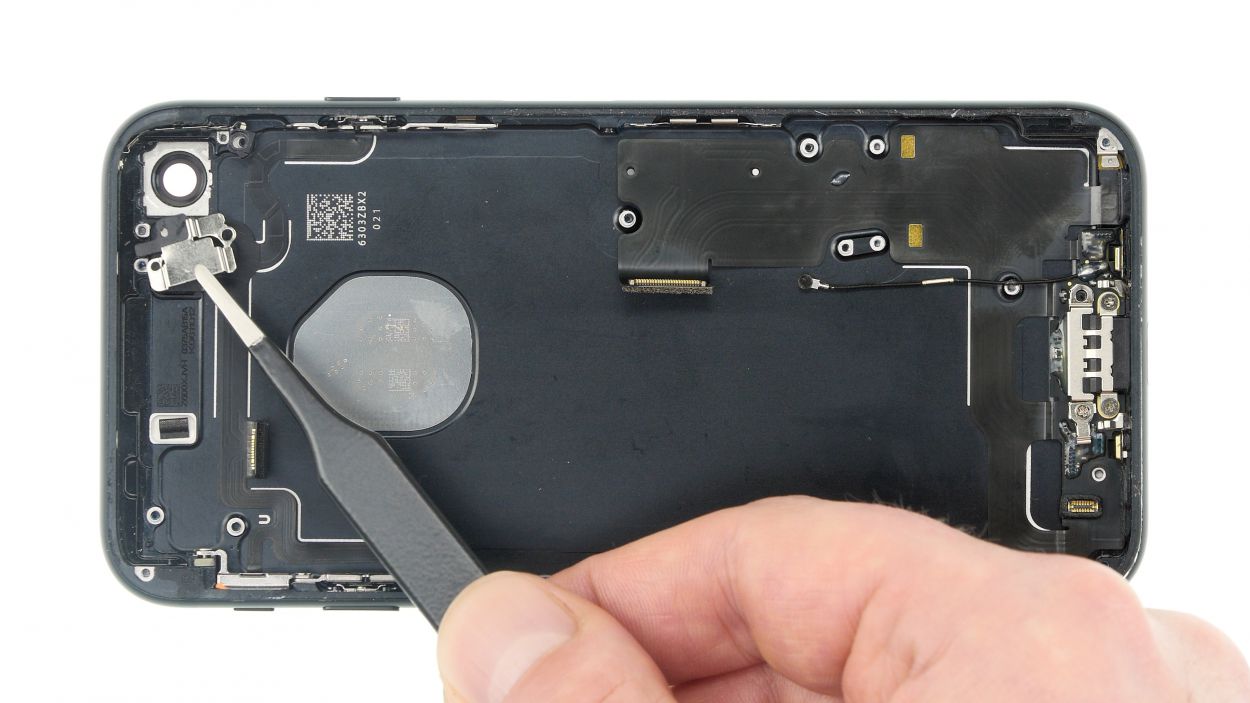
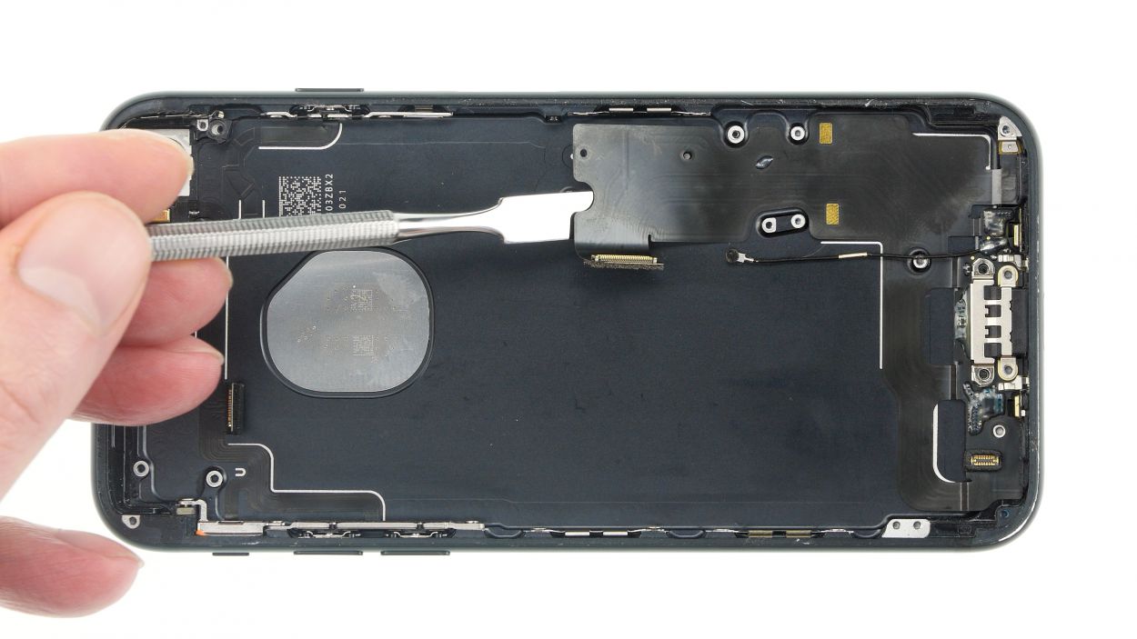
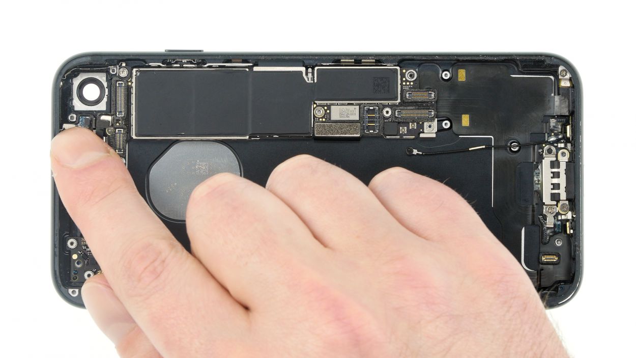
– First up, grab your spudger and gently wiggle that Wi-Fi antenna connector free from the logic board—it’s like giving it a little high five!
– Next, let’s tackle those two Phillips screws that are keeping the flex cable in check. Unscrew them like a pro and you’re one step closer to victory!
When you’re detaching the Wi-Fi connector, be sure to leverage from the side without the tiny components. This little tip helps keep your device safe from any accidental boo-boos!
One of those cheeky screws is snugly attached to the side of the housing. Keep an eye out for it while you’re on your repair mission!
Tools Used
- heat gun to heat parts that are glued on so they’re easier to remove.
In most cases, you can also use a hairdryer.” rel=”noopener”>Heat gun - Pry Tool
- Wiha PicoFinish Phillips Screwdriver PH00
- Piergiacomi Tweezers 2a SA ESD
- Steel Laboratory Spatula

Step 17
1 × 1,3 mm Phillips
1 × 2,1 mm Standoff
4 × 2,0 mm Standoff
Lightning connector
You’ve got a special screwdriver for those stand-off screws, but if you’re feeling adventurous, a slotted screwdriver can also do the trick to loosen them up!
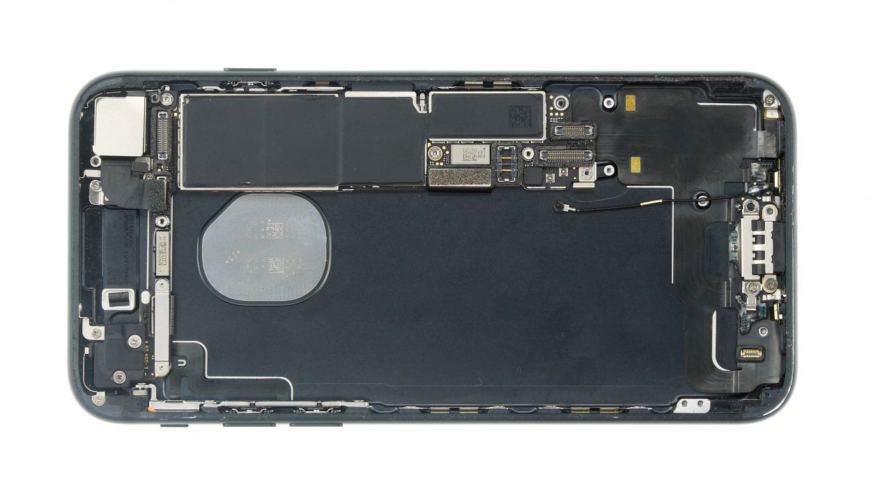
– Alright, let’s get those six screws holding the logic board in place unscrewed! Grab your trusty screwdriver and let’s make it happen!
Step 18

2 × 1,6 mm Phillips
2 × 1,3 mm Phillips
1 × 2,6 mm Phillips
Two sneaky screws are snugly tucked into the back cover frame, each hiding beneath a black sticker. Keep your eyes peeled for these little guys as you embark on your repair journey!
– Kick things off by grabbing your Phillips screwdriver and unscrewing those five screws that are holding the Lightning Connector snugly to the back cover. You’ve got this!
Tools Used
- heat gun to heat parts that are glued on so they’re easier to remove.
In most cases, you can also use a hairdryer.” rel=”noopener”>Heat gun - Wiha PicoFinish Phillips Screwdriver PH00
- Steel Laboratory Spatula
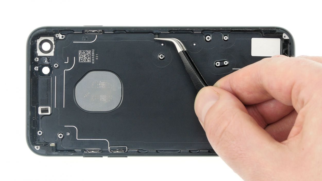
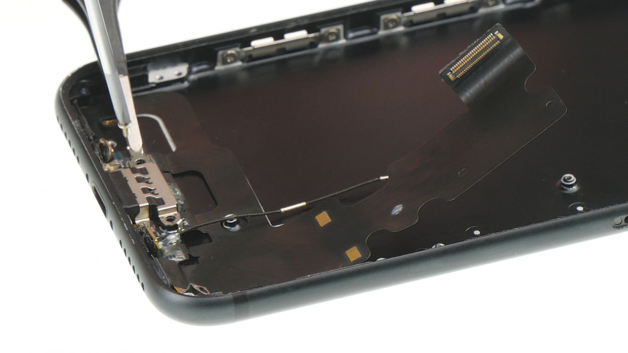
Step 19

5 × 2,9 mm Phillips
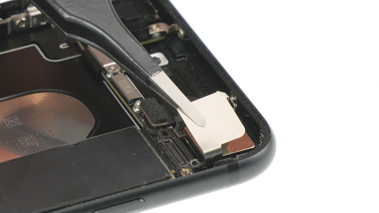
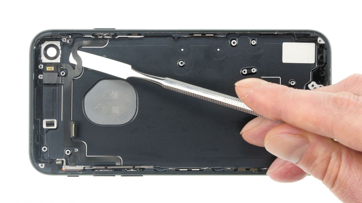
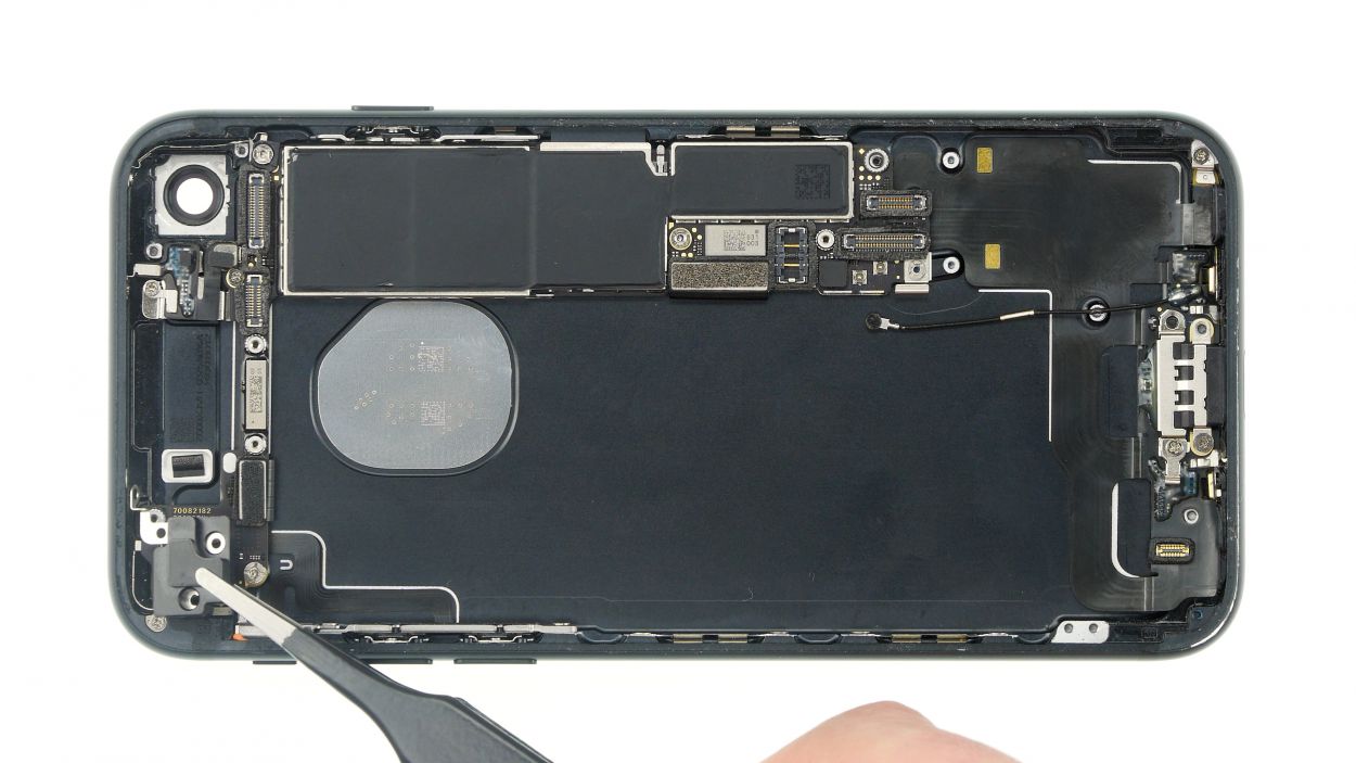
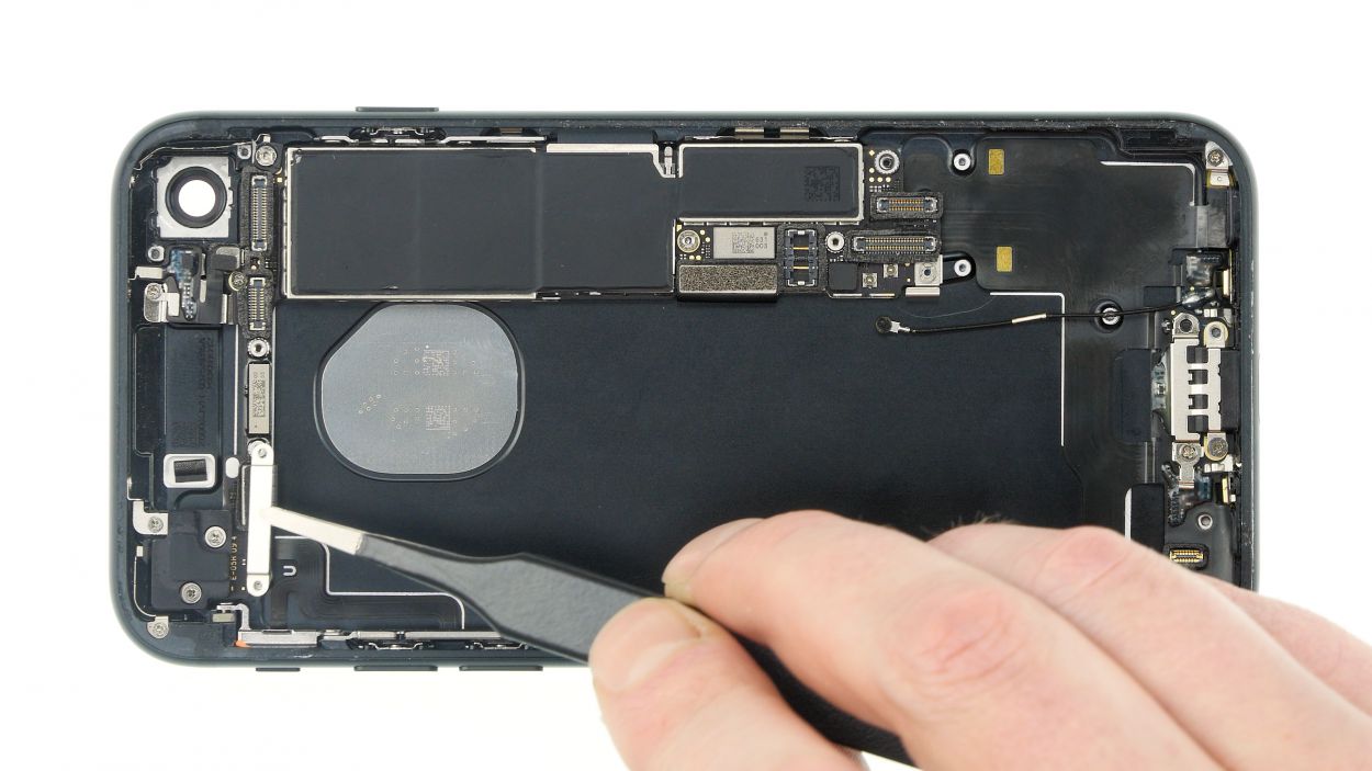
– First off, grab your trusty Phillips screwdriver and let’s tackle those five screws holding the flex cable for the standby and volume buttons. You got this!
– Next up, give that cable set a little warmth with your hot air tool. Just a quick heat-up will do the trick! After that, gently ease it away from the bottom of the back cover using your steel spatula—like a pro!
– Finally, loosen the small gold ambient microphone from its lead and remove the entire cable set. You’re almost there!
Tools Used
- heat gun to heat parts that are glued on so they’re easier to remove.
In most cases, you can also use a hairdryer.” rel=”noopener”>Heat gun - Wiha PicoFinish Phillips Screwdriver PH00
- Piergiacomi Tweezers 2a SA ESD
- Steel Laboratory Spatula
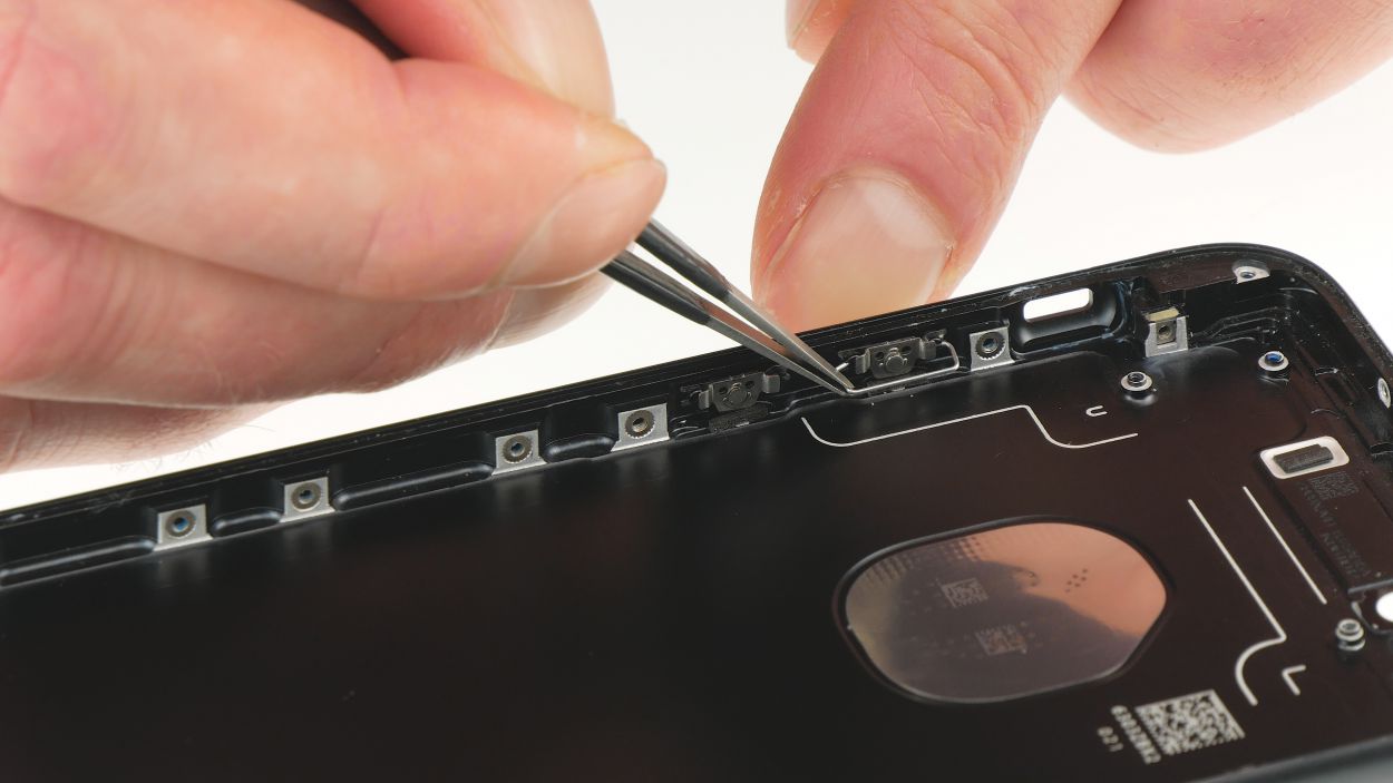
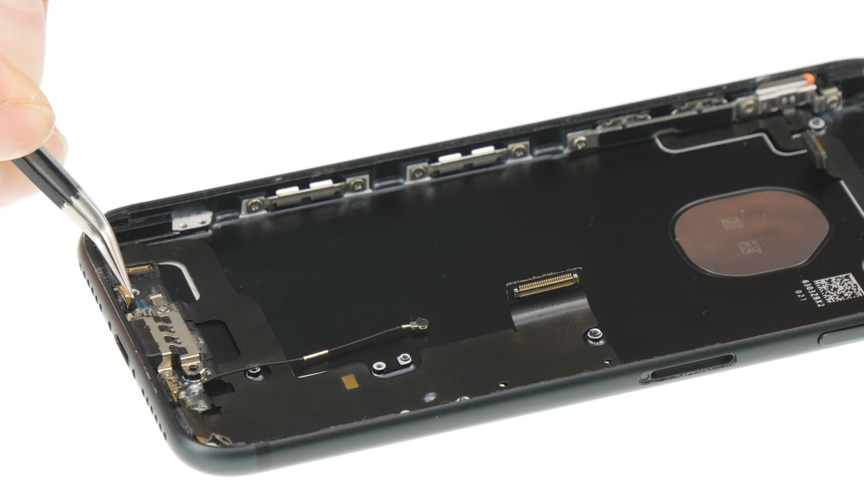
Step 20
1 × 1,4 mm Phillips
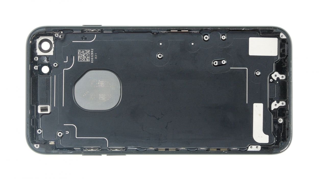
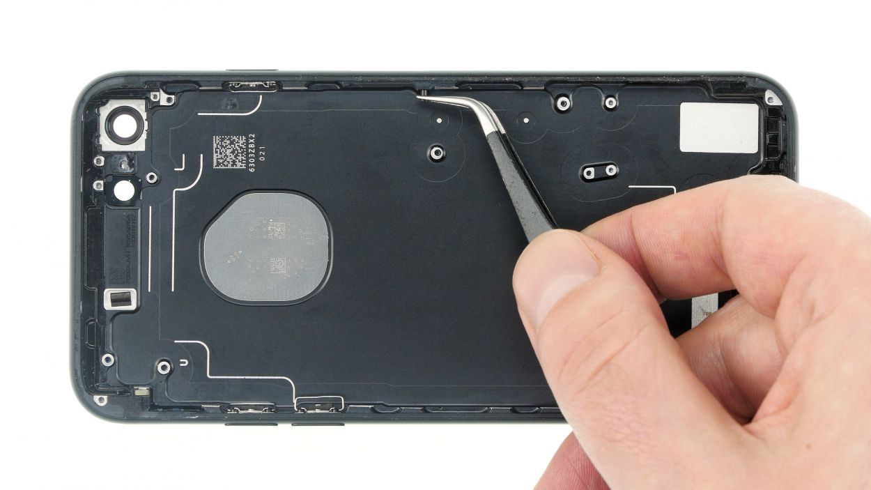
– Unscrew the Phillips screw and gently remove the guide rail from the edge of the back cover. It’s like giving your phone a little hug goodbye!
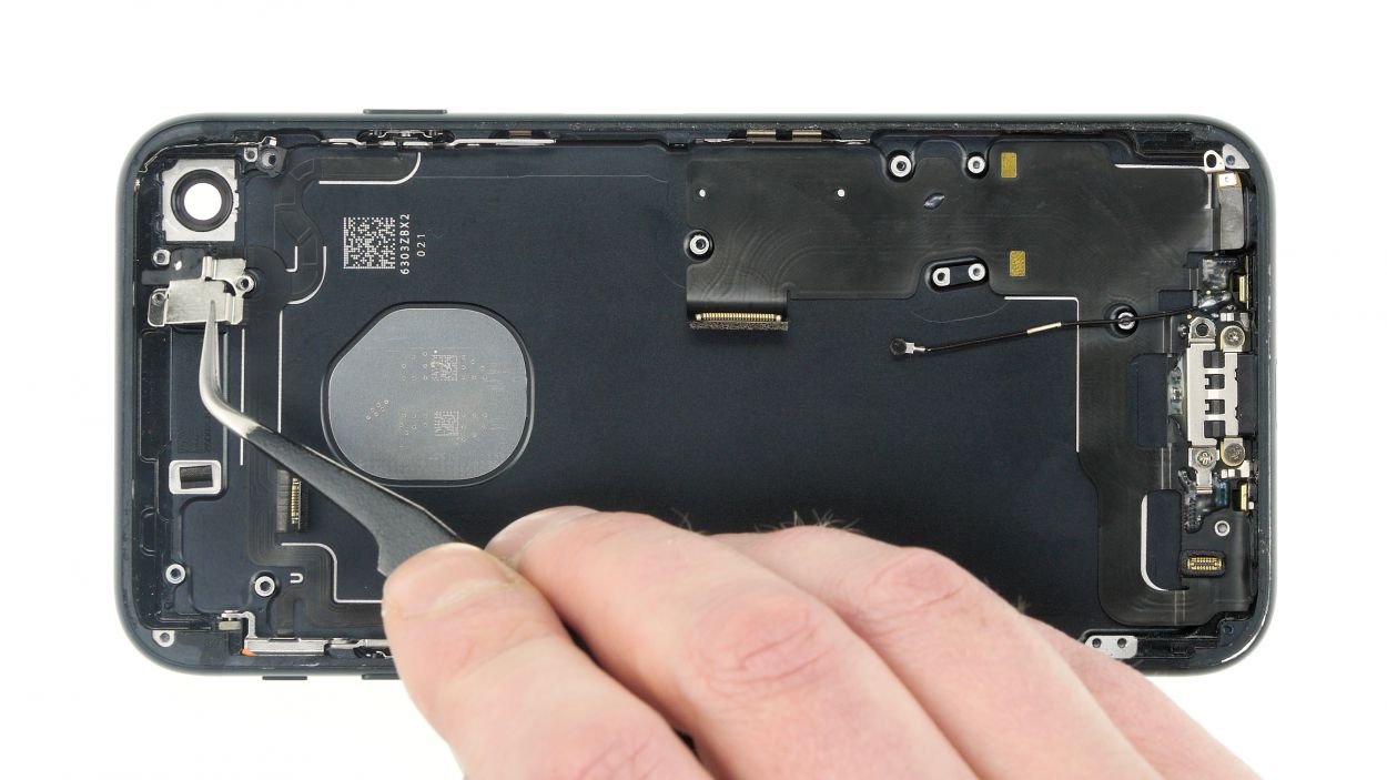
Step 21

6 × 1,5 mm Phillips
Don’t forget to bring that little plastic pin along for the ride to the new back cover! It’s like the cherry on top of your repair sundae.
– Let’s get those three fixing clamps loosened up from the edge of the back cover! Unscrew those two Phillips screws and let them go free.
– And don’t forget to grab that little plastic pin next to the SIM tray opening and give it a new home!
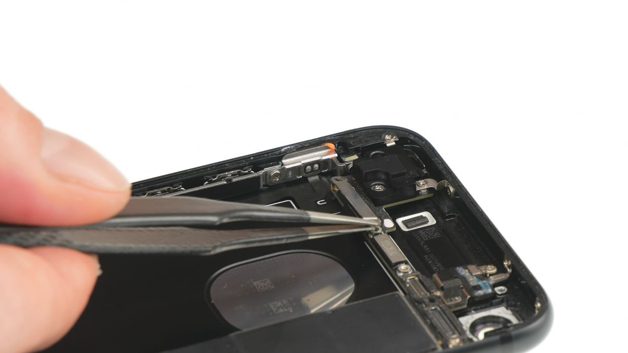
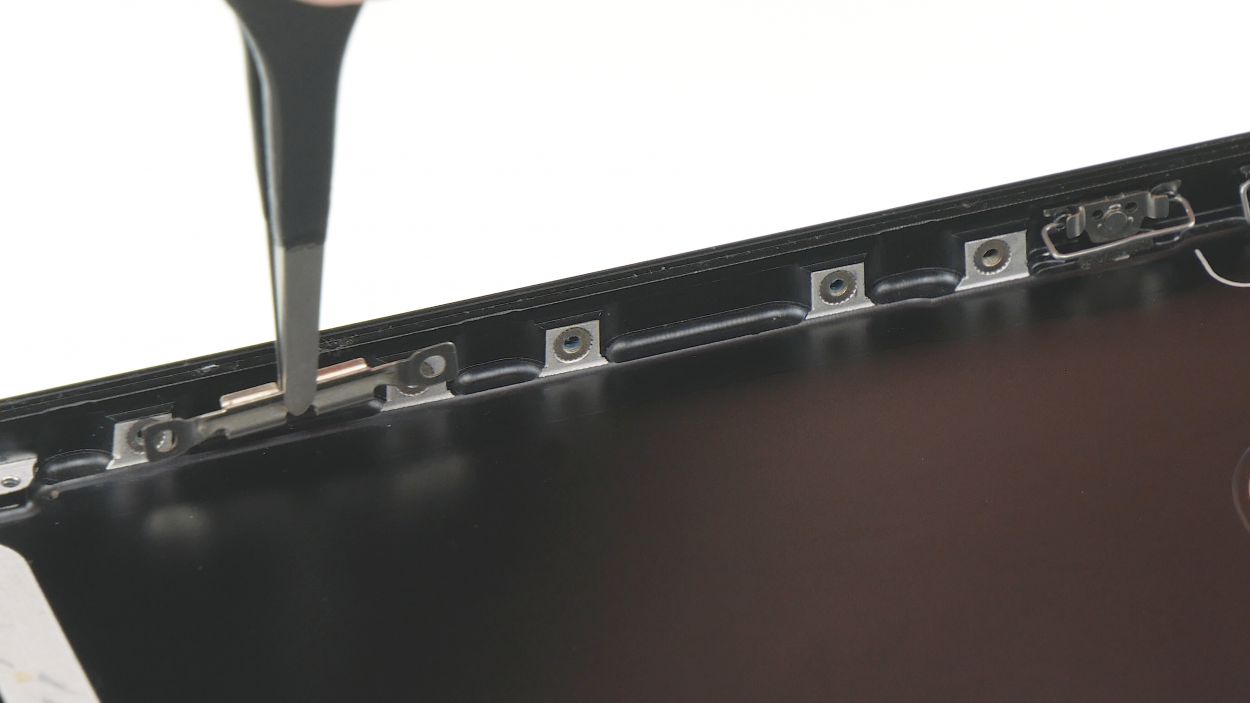
Step 22
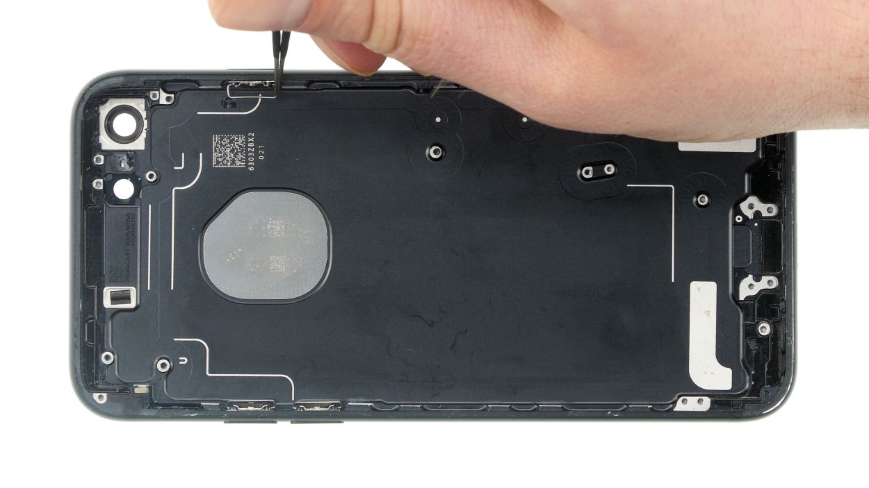
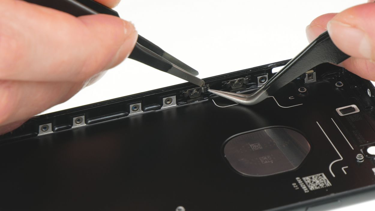
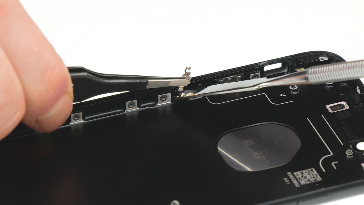
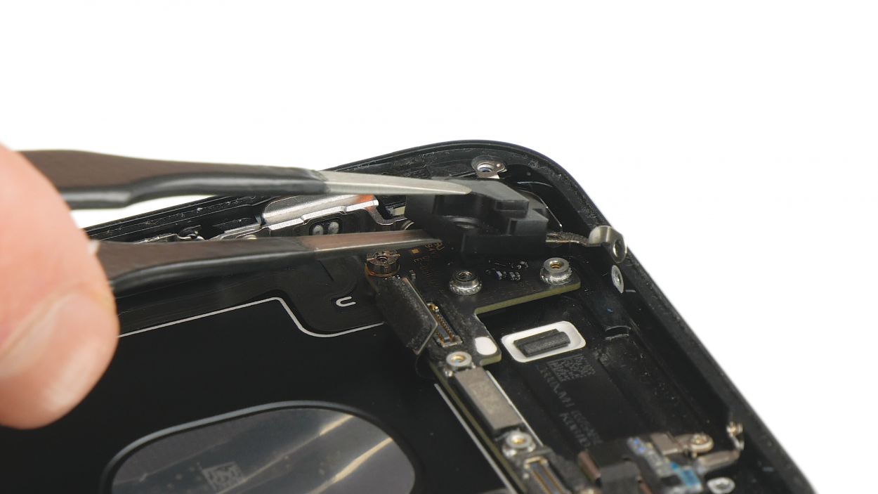
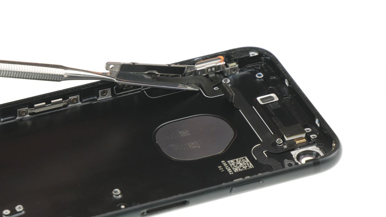
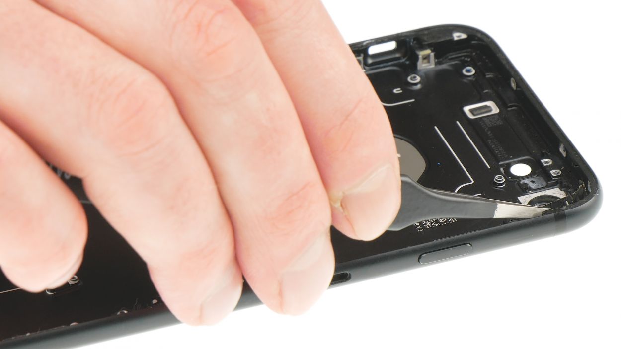
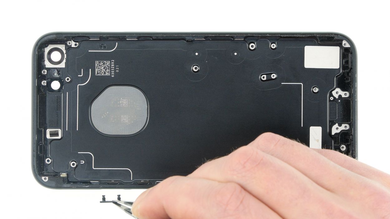
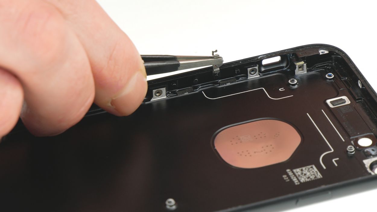
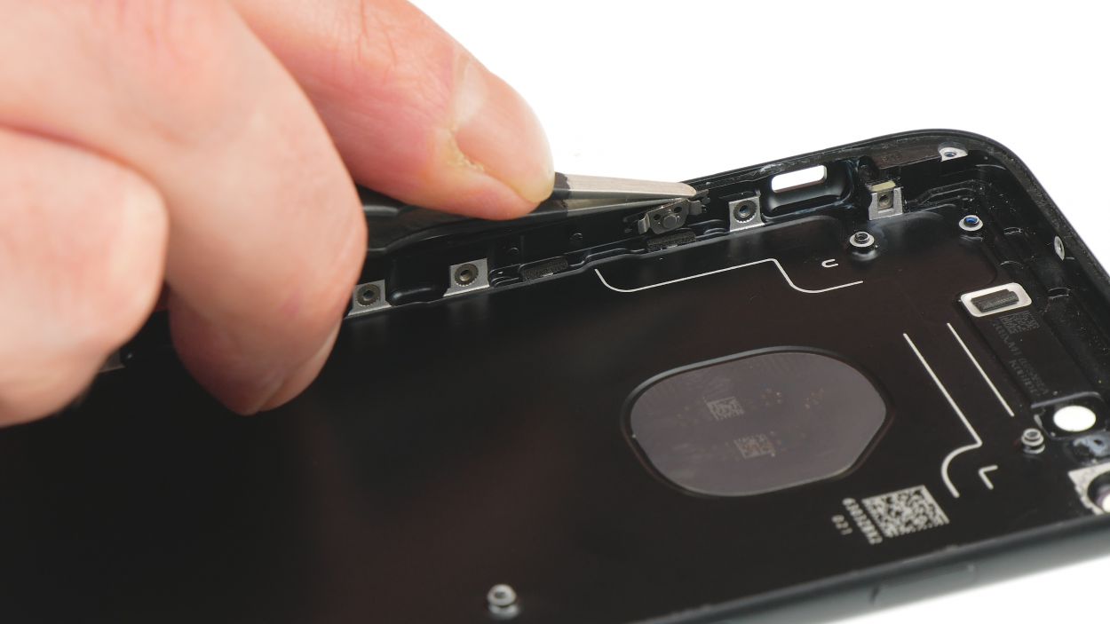
– Using your trusty tweezers, gently coax the clamps of the sleep/wake button out of the back cover frame. You got this!
– Next, give that bracket a little push upwards from one side and carefully peel it away from the back cover frame.
– Now it’s time to press out the button from inside the frame. You’re on a roll!
– Repeat this process for the volume buttons and you’ll be all set!
Tools Used
Step 23
– Get those cool stickers or plastic holders ready and attach them to your shiny new back cover!
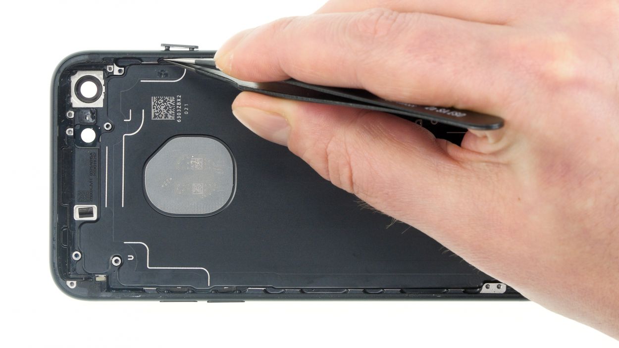
Step 24
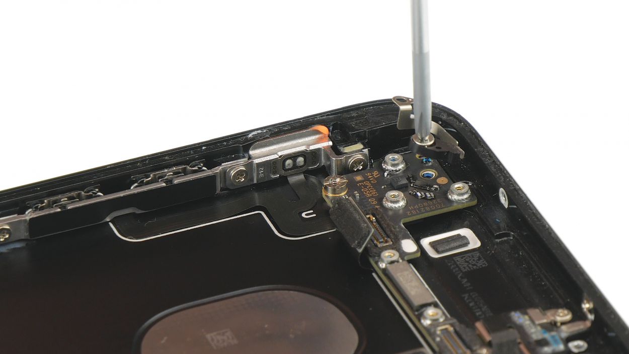
– Slide the sleep/wake button back into the back cover frame by giving it a gentle press from the outside.
– Pop the bracket into place on the inside of the back cover frame, starting vertically and then giving it a little twist to sit horizontally.
– Now, grab your tweezers and carefully hook those clamps of the sleep/wake button into the key holder. A little finesse goes a long way here!
– Do the same smooth moves for the volume keys, and you’re all set!
Tools Used
Step 25

6 × 1,5 mm Phillips
– Pop that little plastic pin into the cozy spot next to the SIM tray opening on the edge of the back cover. It’s like giving your phone a friendly nudge!
– Now, let’s line up those three mounting clamps along the edge of the back cover and secure them with two Phillips screws each. You’re doing great!
Step 26
1 × 1,4 mm Phillips
– Reattach the rail to its original spot and secure it with that Phillips screw. You’re almost there!
Step 27
5 × 2,9 mm Phillips
Keep that cable nice and flat—no bends allowed! And don’t forget to check that the microphone and flash are snugly in place, just the way they should be.
Once you’ve tightened those screws, take a moment to check how your buttons are feeling. If they need a little tweak, adjust those screws to get everything just right!
– First, pop that volume control cable into place and give it a gentle press down onto the bottom of the back cover. You’re doing great!
– Next, secure it to the back cover with those five Phillips screws. Tighten them up like a pro!
Tools Used
Step 28
– Nestle that Lightning connector flex cable back into its cozy spot and give it a gentle press down against the back cover.
– Guide the socket and those two shiny golden microphones back into their snug homes along the edge of the rear case.
– Secure everything in place with five screws and a little silver bracket—just like putting the cherry on top of a sundae!
2 × 1,3 mm Phillips
2 × 1,6 mm Phillips
1 × 2,6 mm Phillips
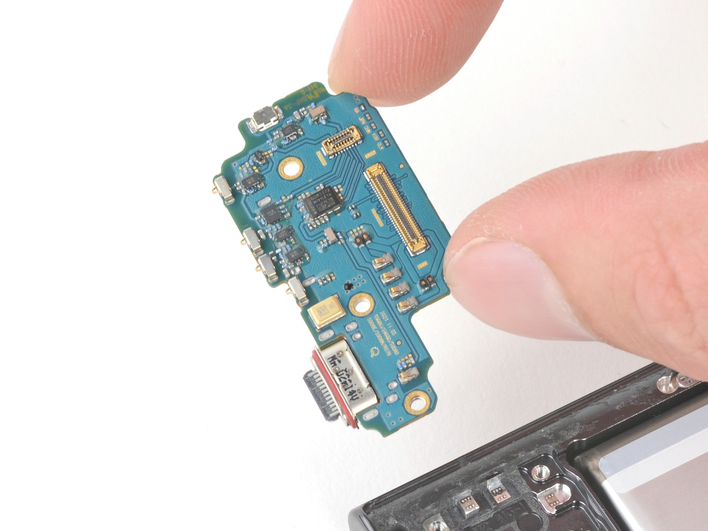
Hey there! Just a quick heads up: make sure to align that flex cable of the Lightning connector just right! If it’s not lined up, the connector won’t play nice with the logic board. Keep an eye out for those two small white dots on the bottom of the back cover—they should peek through the cut-outs in the flex cable (check out Figure 4 for a visual!).
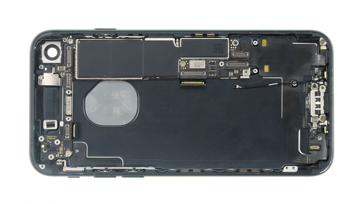
Step 29
1 × 1,3 mm Phillips
1 × 2,1 mm Standoff
4 × 2,0 mm Standoff
– First things first, pop that cover back on the flash light. It’s like giving your phone a cozy blanket!
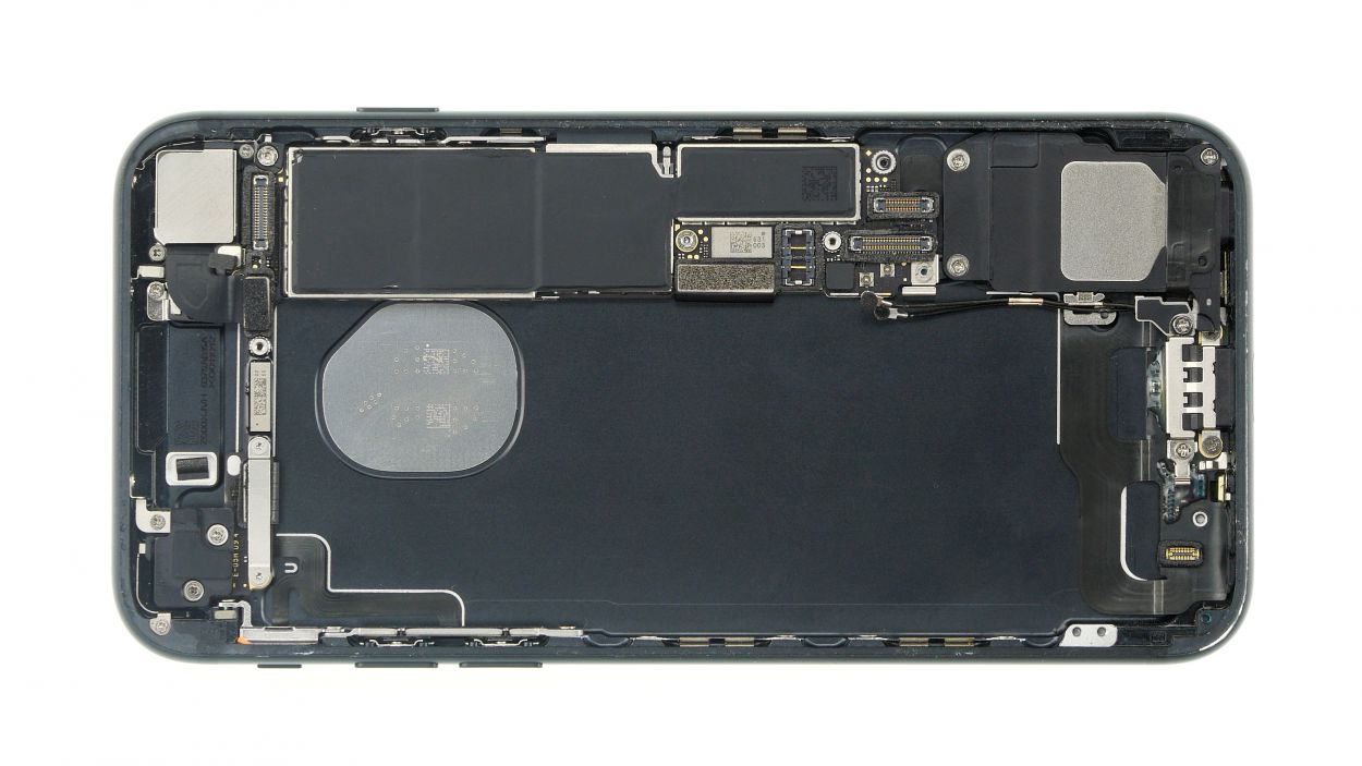
– Next up, gently place the logic board back where it belongs. Make sure that camera lead is sitting pretty above the board.
– Finally, secure everything in place with those trusty screws. You’ve got this!
Step 30
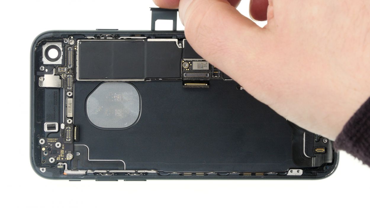
If you’re having a bit of a struggle getting it in, take a moment to check where the logic board is sitting. It might just need a little nudge to fit perfectly!
– Now gently slide that SIM tray back into its cozy little home in the opening. Just give it a nudge and watch it snuggle right in!
Step 31
Lightning connector
Volume control cable connector
Hey there! Just a friendly reminder: be gentle when connecting those sensitive connectors. No need to muscle them in—let’s keep everything happy and in its place!
– Reconnect the Lightning connector and the volume control cable connector until you hear a satisfying click, letting you know they’re snug and secure!
Step 32
1 × 1,3 mm Phillips
1 × 1,2 mm Phillips
Antenna connector
– Place the Wi-Fi antenna back where it belongs in the rear case of your iPhone and tighten those screws like a champ.
– Give it a gentle press to make sure everything sticks together nicely.
– Finally, reconnect that antenna connector until you hear a satisfying click, ensuring it’s snug and secure.
Step 33

1 × 2,1 mm Phillips
1 × 1,3 mm Phillips
1 × 1,6 mm Phillips
3 × 1,1 mm Phillips
– Reattach the small connecting plate to its original spot and secure it with those two Phillips screws—easy peasy!
– Next up, pop that antenna cover back on and fasten it down with Phillips screws too. You’re almost done!
Step 34
2 × 1,1 mm Y-Type
– Time to pop that shiny silver cover back over the volume control cable connector!
– Secure it in place with those two Y-type screws, and you’re all set!
Step 35
Camera Connector
1 × 2,3 mm Phillips
1 × 1,3 mm Phillips
– Carefully slide the iSight camera back into its cozy spot in the back cover and connect its little buddy, the connector.
– Now, cover that camera with the plate and secure it in place with some screws—easy peasy!
Step 36

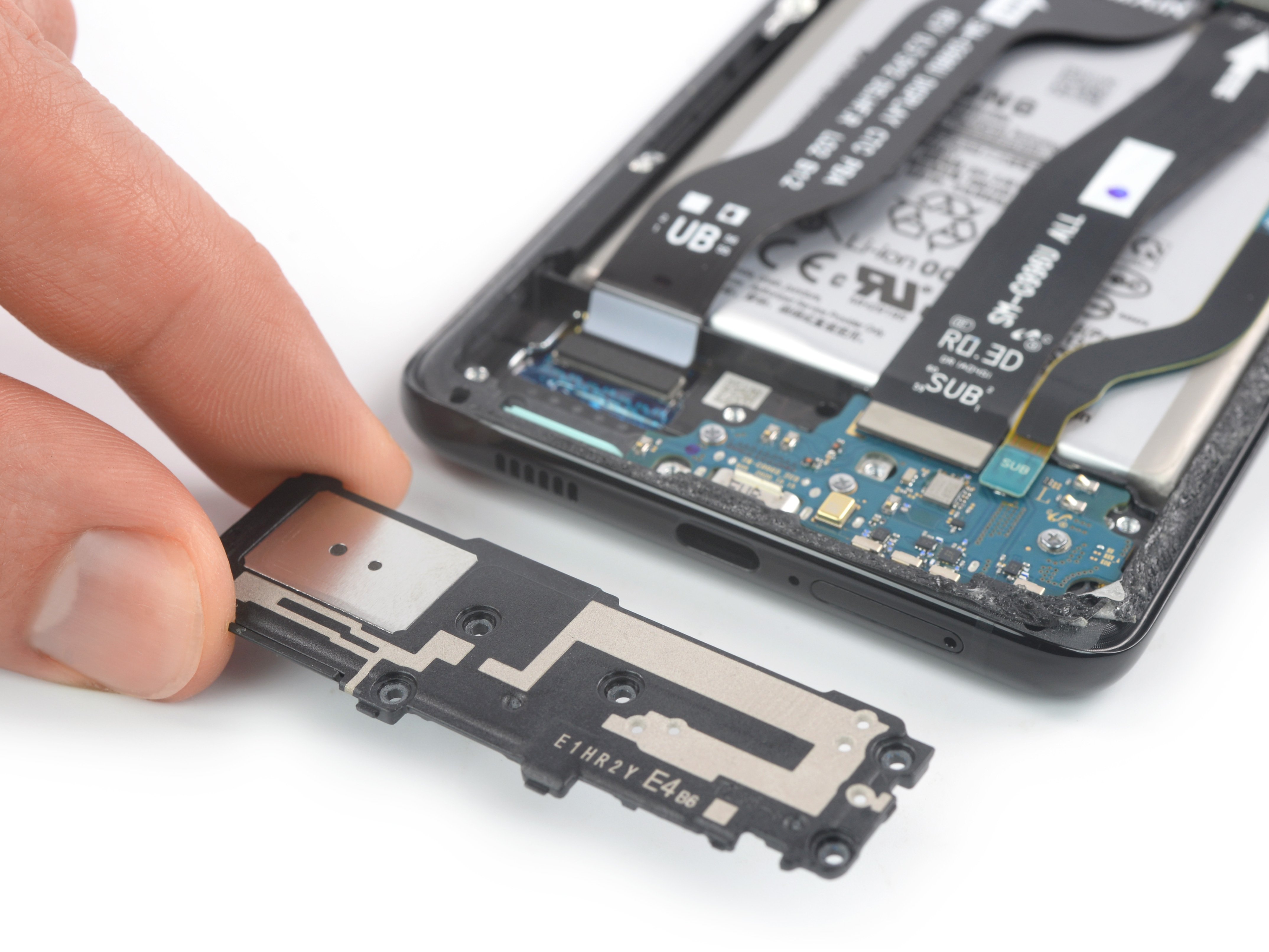
When you’re putting the speaker back in, just a friendly reminder to watch those antenna cables! We don’t want them getting pinched in the process!
– Pop that speaker back into its cozy spot at the bottom of the back cover.
– Secure it with those four Phillips screws—tighten them up like a pro!
– Now, let’s get those antenna cables positioned just right, slide them into the lead, and connect them to the board.
Step 37
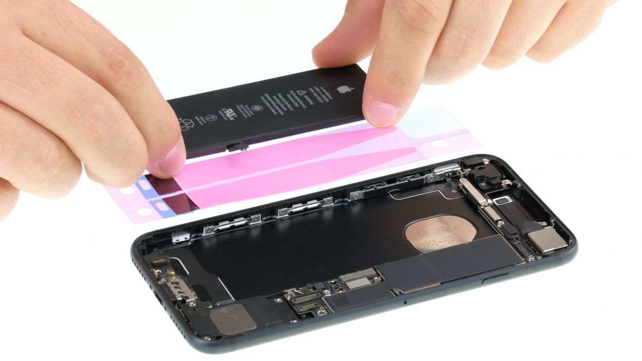
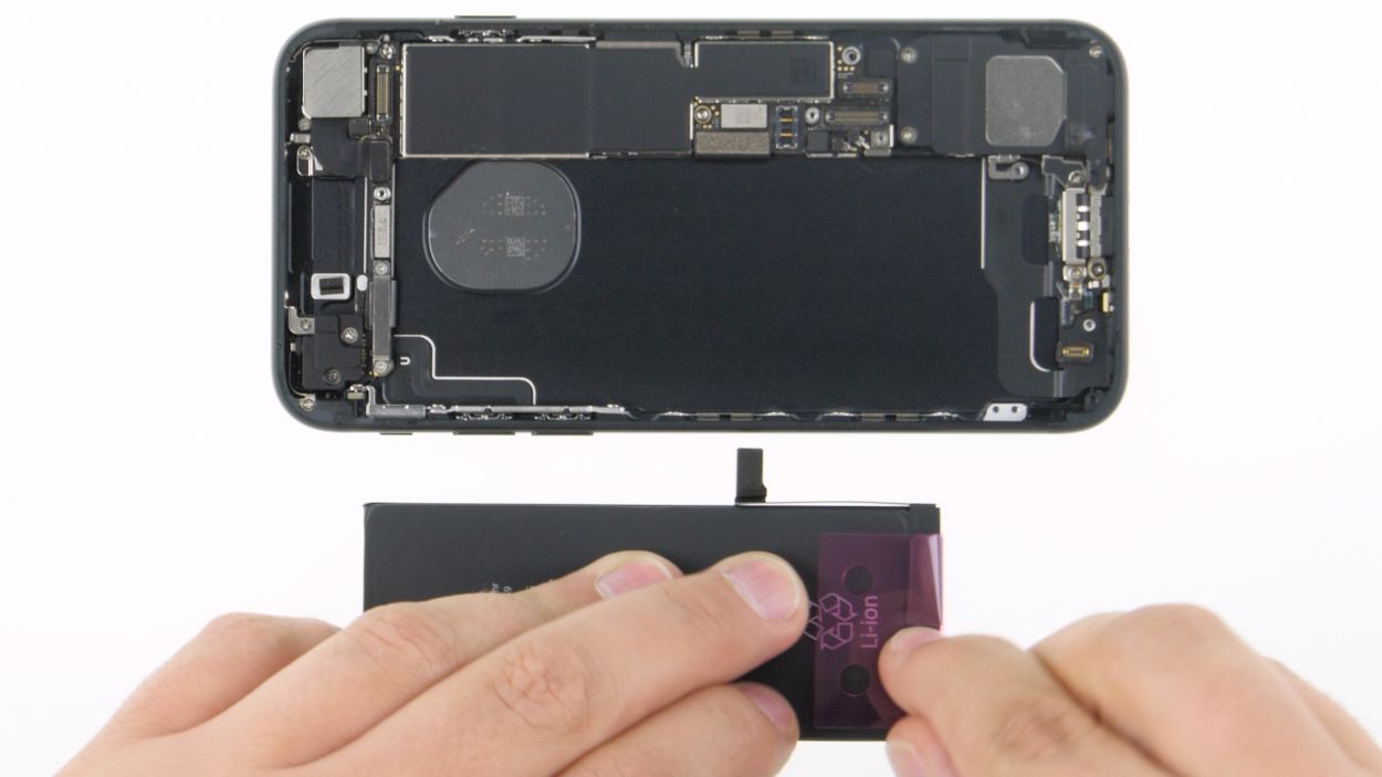
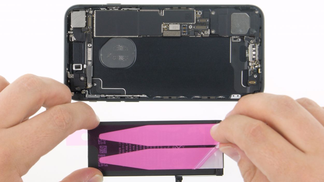
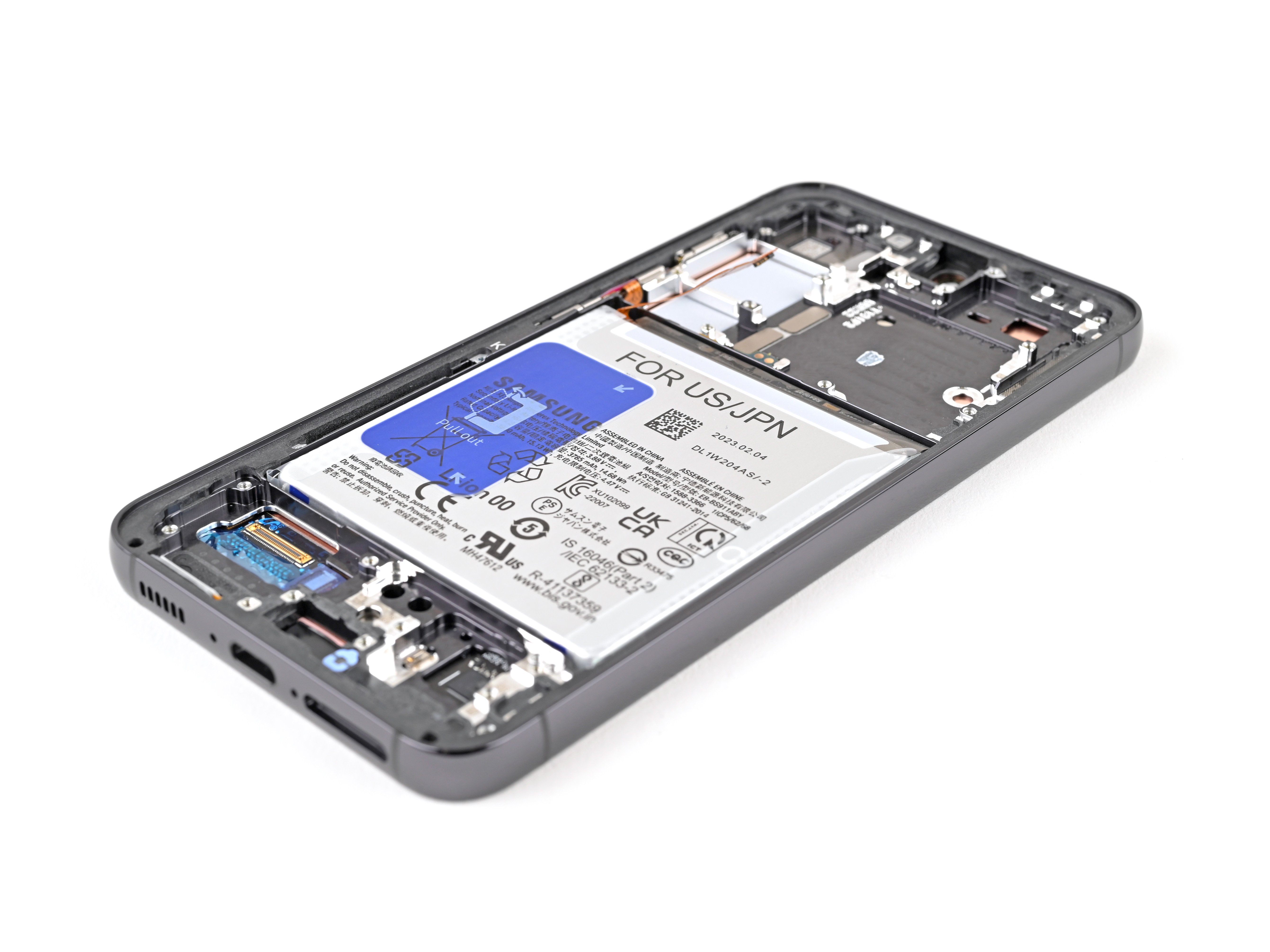
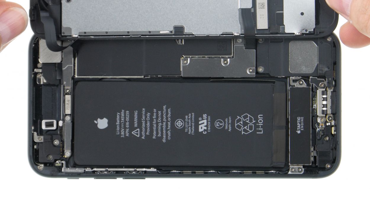
Get those adhesive+strips+iPhone+7&crid=1TJIMMAJSUJUZ&sprefix=repair+tools%2Caps%2C165&linkCode=ll2&tag=salvationrepa-20&linkId=c486487cf454ce8edd6f5beefab4110f&language=en_US&ref_=as_li_ss_tl’>adhesive strips lined up just right! Give them a test run by placing them in your iPhone before you commit. It’s like a dress rehearsal for your battery!
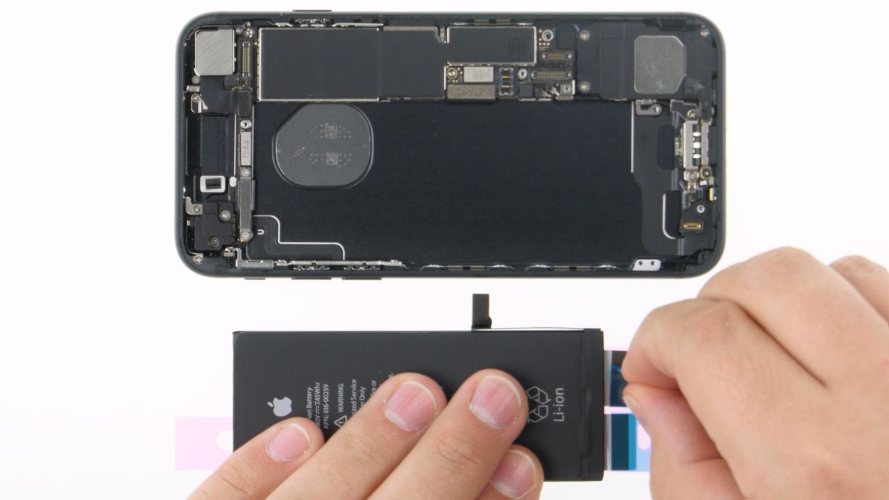
– Peel off that big blue protective film from the adhesive+strips+iPhone+7&crid=1TJIMMAJSUJUZ&sprefix=repair+tools%2Caps%2C165&linkCode=ll2&tag=salvationrepa-20&linkId=c486487cf454ce8edd6f5beefab4110f&language=en_US&ref_=as_li_ss_tl’>adhesive strips and stick them right in the center on the bottom of your shiny new battery, adhesive side down, of course!
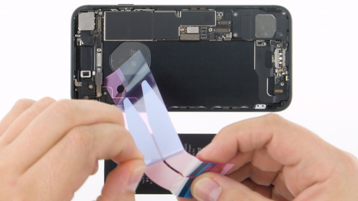
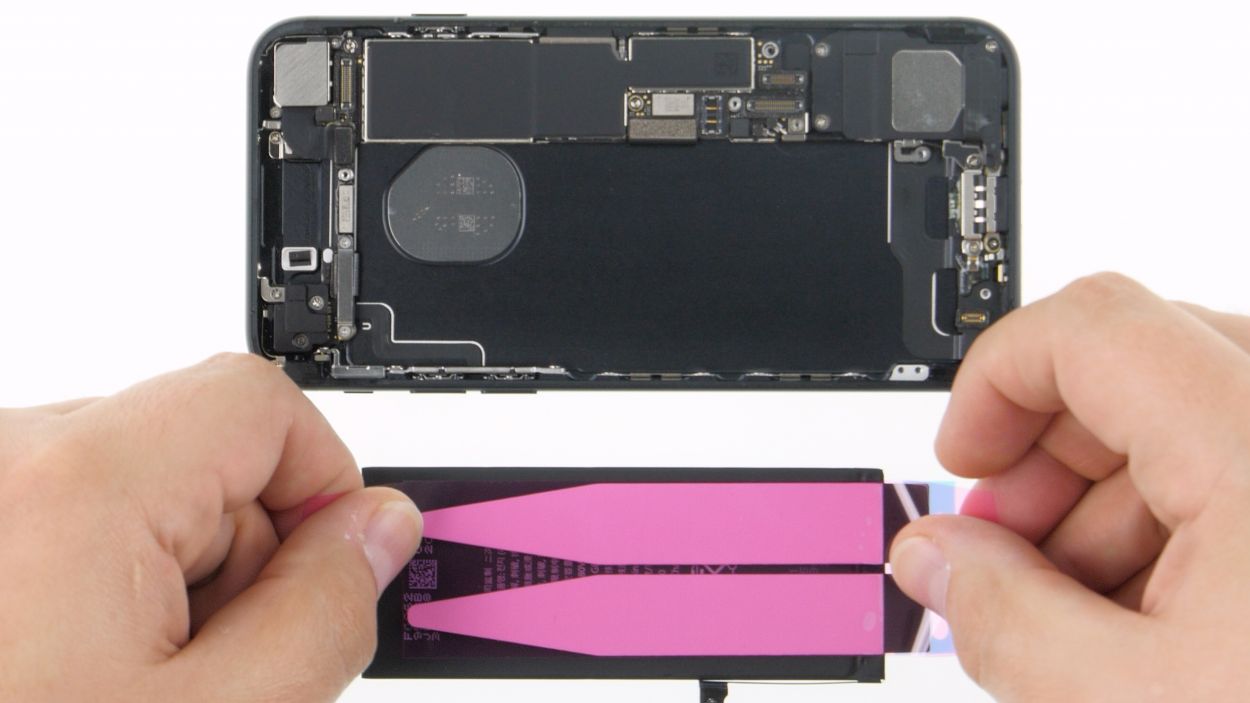
– Flip that battery over and take off the little blue protective film from the adhesive tabs.
– Give those tabs a good press on the edge of the battery, then flip it back over.
– Now, gently pull away the remaining pink protective film from the adhesive+strips+iPhone+7&crid=1TJIMMAJSUJUZ&sprefix=repair+tools%2Caps%2C165&linkCode=ll2&tag=salvationrepa-20&linkId=c486487cf454ce8edd6f5beefab4110f&language=en_US&ref_=as_li_ss_tl’>adhesive strips. You’re doing great!

Step 39


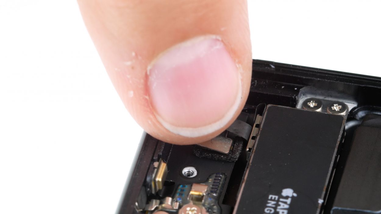
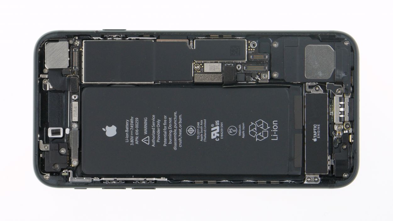
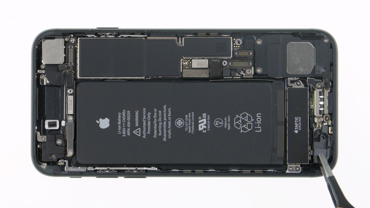
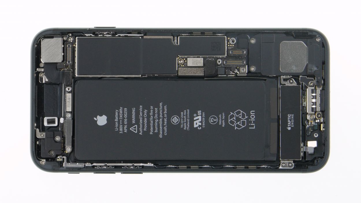
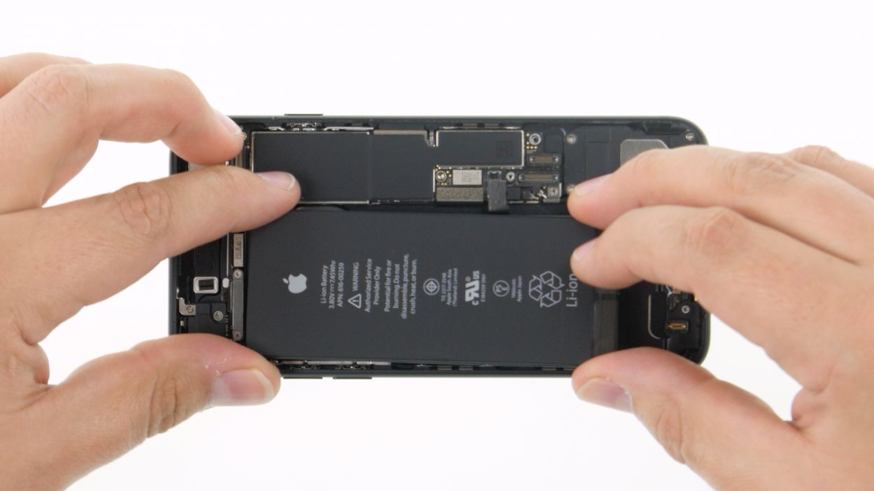
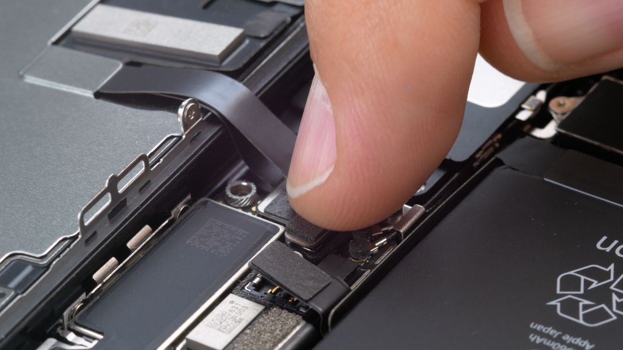
– Slide the Taptic Engine back into its cozy spot nestled between the battery and the Lightning connector.
– Secure that Taptic Engine in place with three trusty Phillips screws.
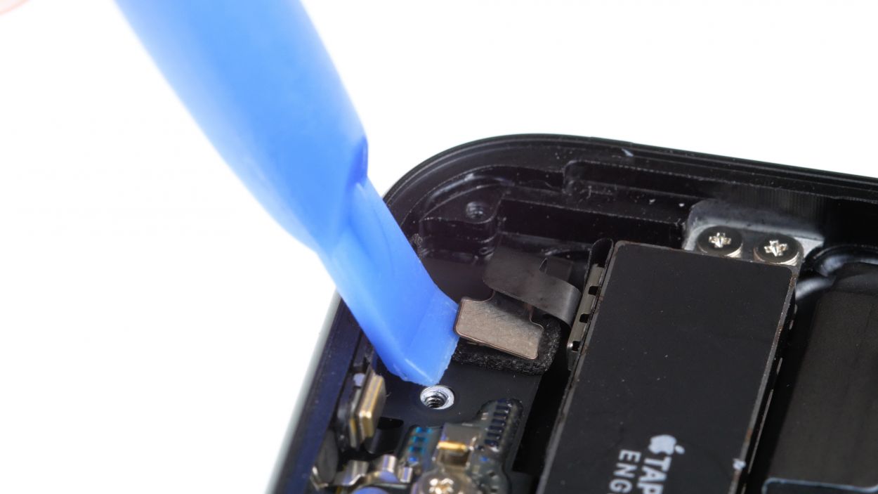
– Next up, connect the Taptic Engine connector—make sure it’s snug!
– Finally, pop the plastic cover back over the connector and secure it with those two Phillips screws. You’re doing awesome!
Step 40

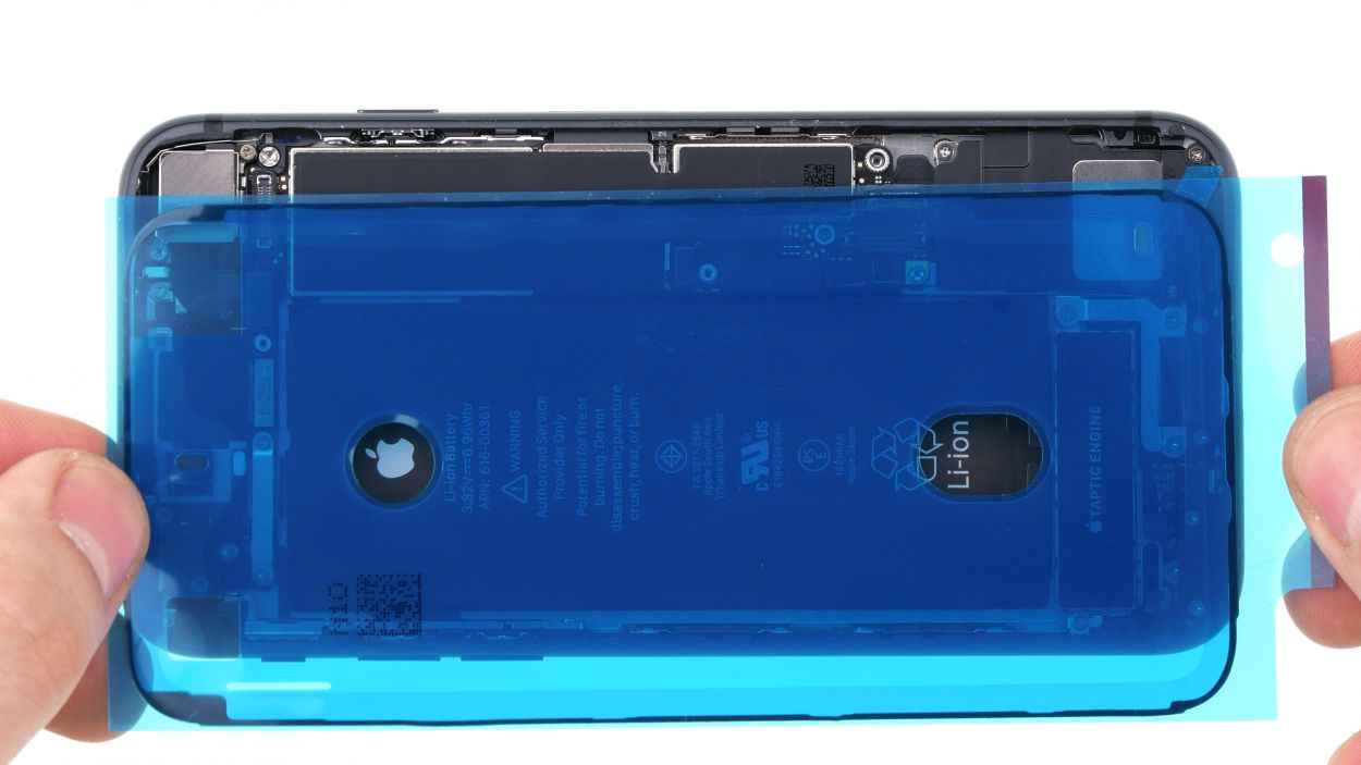
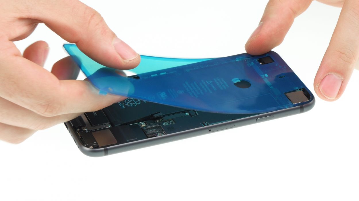
– To ensure that the new adhesive frame fits like a glove, start by giving your back cover and display frame a good scrub to remove any old adhesive residue. We want a fresh start!
– Next, go ahead and place the adhesive frame on the back cover to align it just right. You’ve got this!
Tools Used
Step 41

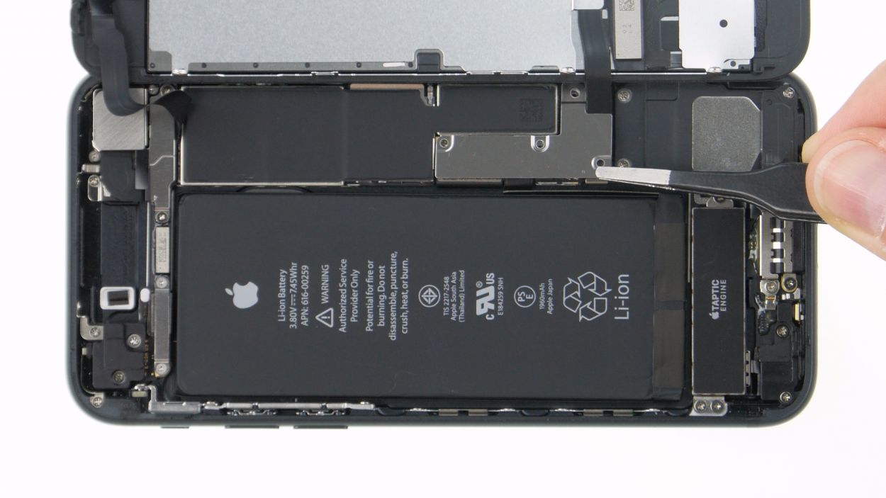
FaceTime connector
2 × 1,2 mm Phillips
Just like when you were unhooking the FaceTime connector, it’s a great idea to prop that display against something sturdy. This way, you can avoid any drama with the flex cables overstretching. Keep it chill and steady!
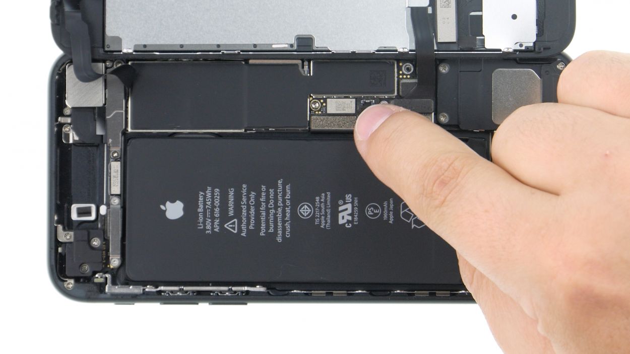
– To get the display unit cozy with the logic board, start by propping it up at the top of the back cover like it’s ready for a big hug.
– Next, give the FaceTime camera connector a gentle nudge with your finger until you hear that satisfying click—it’s like a little handshake!
– Once that connector is happily attached, you can let the display rest on the side of the back cover while you finish up.
Step 42
Display connector
Home button connector
– Reconnect the home button and display connector to the logic board with a gentle touch, just like giving your device a high five!
Step 44
– Gently lay the display alongside the back cover frame and fold it over with care.
– Slide the display toward the sleep/wake button, ensuring the lugs on the display fit snugly into the back cover.
– Finally, press the display down into the frame, making sure to cover every inch for a secure fit.
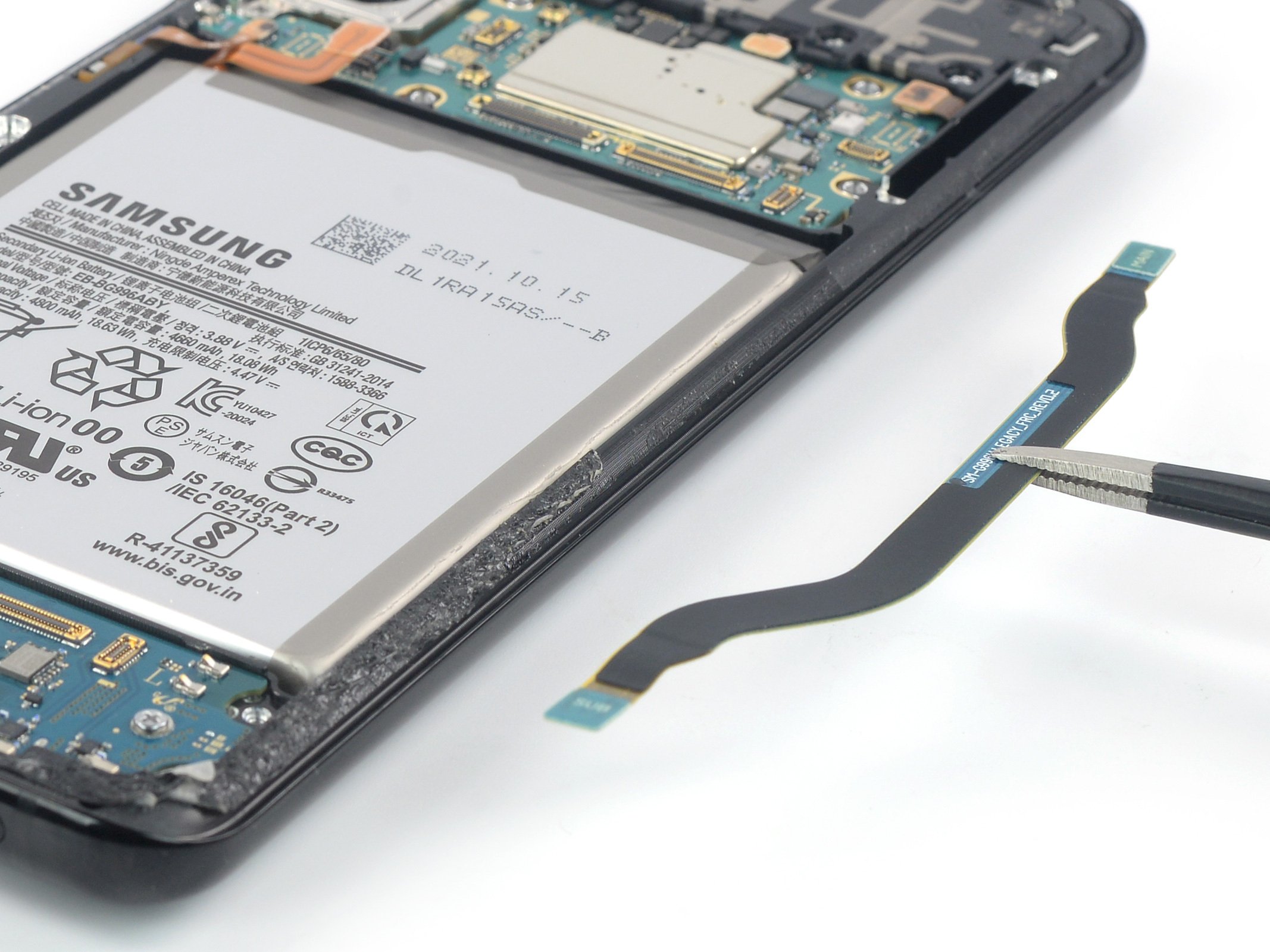
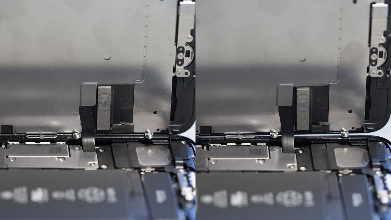
Wrong position
Right position
Hey there! Just a quick reminder: that shiny silver chip on the cable needs to be in the exact same spot as before (check out the photo for reference!). If it’s off by even a smidge, you might see some funky discolorations and spots on your screen after you’re done. So, if that happens, don’t fret—just give that cable another little nudge to get it back in line!
Step 45

2 × 3,3 mm Pentalobe
– Now let’s tighten those two Pentalobe screws back into place, one on each side of the Lightning connector. You’ve got this!