Samsung Galaxy S23 Screen and Battery Assembly Replacement
Duration: 45 minutes
Steps: 43 Steps
Heads up: this guide is tailored for the screen and battery combo. Grab your tools and let's dive in!
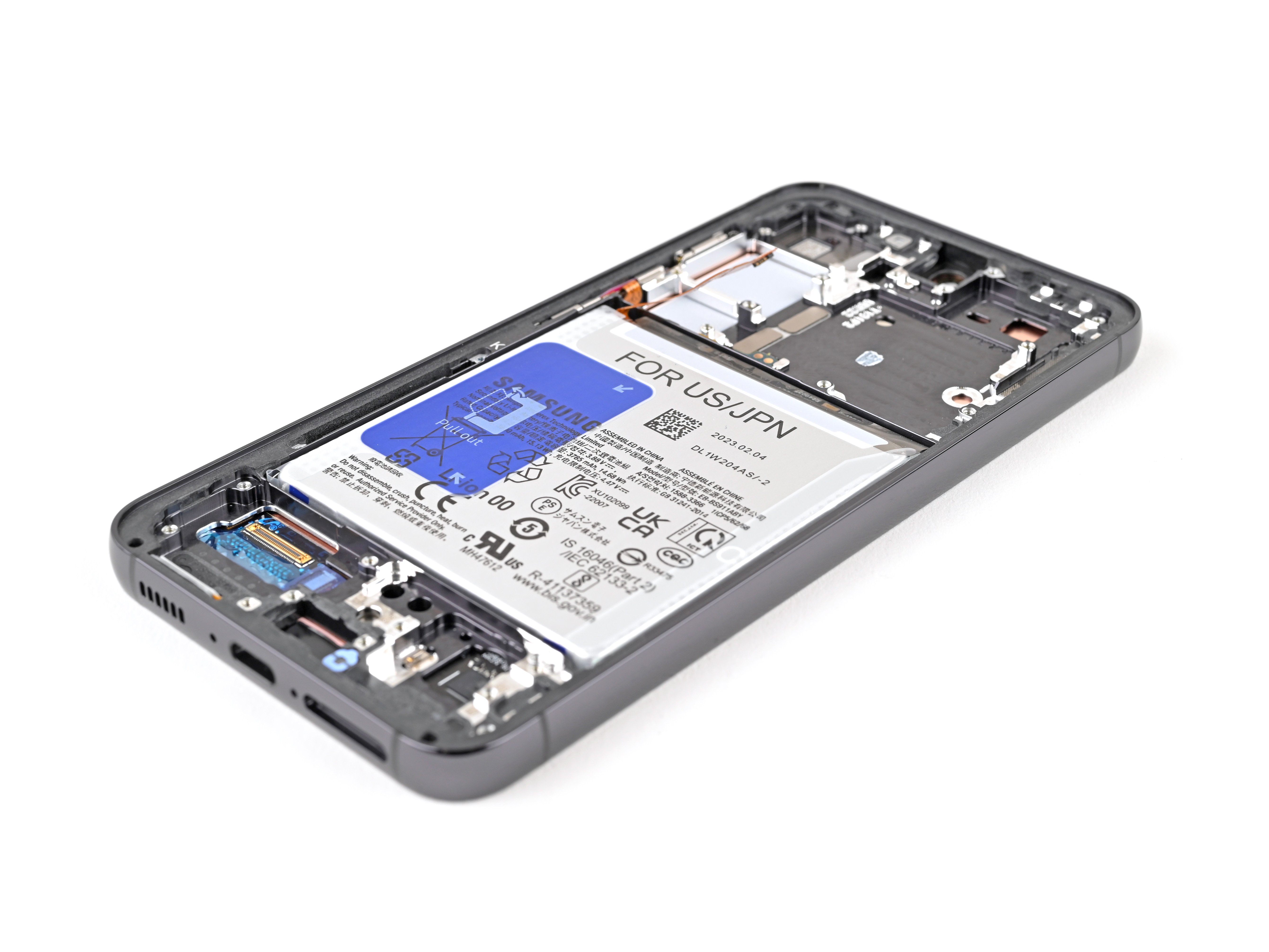
Get ready to dive into replacing the screen and battery assembly on your Samsung Galaxy S23! This guide is all about the screen and battery assembly, which means you've got the screen, battery, and frame snugly packed together in one unit. Make sure you’ve got the right part in hand before kicking off the repair adventure. If it’s just the screen you’re swapping out, we've got a guide for that too! Before you start taking your device apart, it’s super important to completely discharge the battery. This little step helps keep things safe by lowering the chances of a thermal mishap if the battery gets a little too cozy with your tools. If you notice that your battery is swollen, be sure to take the right precautions. Remember: while reapplying the back cover adhesive is key to retaining that water resistance, your device might lose its IP (Ingress Protection) rating after the repair. So, let’s get started!
Step 1


Let your phone's battery dip below 25% before you get started—lithium-ion batteries can be a bit feisty when charged. If yours looks swollen, handle with care and keep things chill.
- First things first, let's disconnect any cables from your phone. Give it some space!
- Now, press and hold the side button along with the volume down button, then tap 'Power off' to gracefully shut down your phone.
Step 2

You can use a hair dryer, heat gun, or hot plate to loosen things up, but go easy on the heat—your phone’s screen and battery aren’t fans of getting toasted.
- Warm up an iOpener and place it on the right edge of the back cover for two minutes to loosen that stubborn adhesive.
Tools Used


Step 3


Having a tough time getting a gap started? No worries! Just apply a little more heat to loosen up that adhesive. But, be sure to follow the iOpener instructions closely so things don’t get too toasty.
- Grab a suction handle and stick it to the back cover, aiming for the center of the right edge.
- Give the suction handle a solid, steady pull—think gym day—to pop open a gap between the cover and the frame.
- Slide an opening pick into that new gap. Smooth moves!
Tools Used

Step 4


- Gently glide the pick along the right edge, back and forth, to break that adhesive seal. You're doing great!
- Keep the pick snugly in place near the bottom right corner to stop that pesky adhesive from sticking back together.
Step 5

- Warm up the bottom edge of the back cover with a heated iOpener for about two minutes—think of it as a cozy blanket for your device before you get to work.
Tools Used
Step 6


- Slide a second pick into the bottom right corner—like a pro.
- Spin it around that corner to loosen up the sticky stuff holding things together.
Step 7


- Gently slide your opening pick into the bottom left corner to loosen the adhesive's grip.
- Keep that pick in place at the bottom left to stop the adhesive from sealing back up.
Step 8

- Warm up the left edge of the back cover by gently applying a heated iOpener for about two minutes. Keep it steady and let the heat do its thing. If you need a hand, you can always schedule a repair.
Tools Used
Step 9


- Gently swing the opening pick around the bottom left corner to loosen the adhesive. Keep the mood light and steady—you're making progress one step at a time. If you need a hand, you can always schedule a repair.
Step 10


- Pop in a third opening pick down at the bottom left corner—like adding another player to your team.
- Glide your pick up toward the top left corner to loosen that sticky adhesive. Smooth moves only!
- Let your pick chill in the top left corner so the adhesive doesn't try any sneaky resealing.
Step 11

- Warm up your iOpener and let it chill on the top edge of the back cover for a solid two minutes.
Tools Used
Step 12


- Pop in a fourth pick at the top left corner to get started.
- Give it a gentle twist around that corner to loosen up the adhesive and make separation smoother.
Step 13


- Gently slide your opening pick into the top right corner to loosen the adhesive grip. Keep the pick there to stop the adhesive from sticking back together. If you need a hand, you can always schedule a repair.
Step 14


Steer clear of the rear cameras with your pick! Giving those lenses a little nudge could lead to some unwanted damage. Let's keep them safe and sound!
There's a leftover patch of adhesive sitting right beneath the flash. You should be able to spot the opening pick through the flash cutout, making it easier to work around it.
- Set your opening pick right by the flash cutout—like it’s got VIP access.
- Slide the pick under the top edge of the back cover; you'll feel it catch on the sticky stuff holding it down.
- Keep gliding the pick down toward the bottom until the adhesive finally lets go and the back cover is free.
Step 15


If that stubborn cover is still clinging to the frame, grab your opening pick and take a lap around the edges until it finally lets go.
Now’s a great time to power up your phone and make sure everything’s working as it should. Once you’re done with your test drive, shut it down completely before moving on to the next step.
- Pop off the back cover and set it aside.
- When you're putting things back together:
- Get rid of any leftover adhesive bits—tweezers or your fingers work great. If it’s being stubborn, a little heat and some isopropyl alcohol (at least 90%) will do the trick.
- For custom-cut adhesives, check out the guide.
- Using double-sided tape? Follow that guide.
Tools Used


Step 16


- Grab your trusty spudger and gently pop up the wireless charging coil connector from the motherboard. Easy does it—no need to wrestle with it.
- When reconnecting these press connectors, line them up with care, and press down on one side till you hear a click, then do the same on the other side. Skip pressing the center. If it’s off-center, those tiny pins can bend and that’s a headache nobody wants.
Tools Used

Step 17


- Grab your Phillips screwdriver and unscrew those thirteen 3.5 mm screws holding down the wireless charging coil and the loudspeaker. First, remove the six screws securing the wireless charging coil, then tackle the seven screws keeping the loudspeaker in place. Need a hand? You can always schedule a repair.
Step 18


- Start by gently inserting the point of your spudger into the notch at the top left corner of the loudspeaker.
- Once it's in there, pry it up carefully to release the loudspeaker from the frame. You've got this!
Tools Used
Step 19


- Gently lift the loudspeaker out of the frame—easy does it, no need to wrestle!
- Take out the wireless charging coil and the loudspeaker from the frame. These two are ready for a break.
- When you’re putting it all back together, give the loudspeaker a solid press around the edges so it snaps right into place like it was meant to be.
Step 20


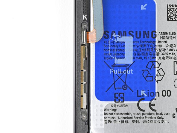
- Grab your spudger and gently pop up the battery press connector—like opening a tiny treasure chest, but less dramatic.
Tools Used
Step 21


- Gently use the spudger tip to lift up and disconnect the earpiece speaker press connector. Nice and easy, just take your time.
Tools Used
Step 22


- Grab your trusty Phillips screwdriver and unscrew those five 3.5 mm-long screws holding the earpiece speaker in place. You're doing great!
Step 23


Be careful where you insert your spudger—going somewhere it shouldn't could dislodge delicate surface-mounted parts. Take it slow and stay precise to keep everything intact. If you need help, you can always schedule a repair.
- Slide the flat end of your spudger right between the bottom edge of the earpiece speaker and the shiny shield on the motherboard. You've got this!
- Give that spudger a little twist to pop the earpiece speaker free from the frame and lift it out like a pro.
- When it's time to put everything back together, remember to tuck the top end of the earpiece speaker into the frame first before pressing down to snap it back in. Easy peasy!
Tools Used
Step 24


- Grab your trusty spudger and gently pop up the primary and secondary interconnect cable connectors from the daughterboard. Smooth moves—just take it slow and watch those tiny connectors!
Tools Used
Step 25


- Do the same thing for both the main and backup interconnect cable connectors on the motherboard—unclip, unplug, and keep those cables out of the way like a pro.
Step 26


- Disconnect both interconnect cables with care.
Step 27

- Grab your Phillips screwdriver and unscrew the three 3.5 mm-long screws holding down the daughterboard. Easy does it!
Step 28
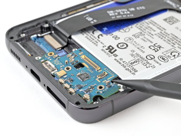

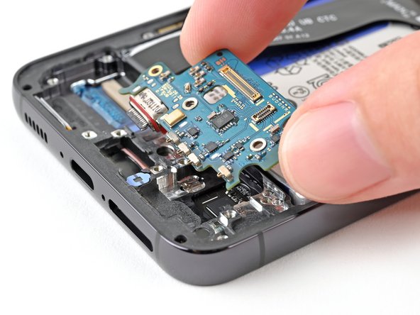
Hey there! Just a friendly reminder: don't go prying against the battery! Instead, give your spudger a little angle and pry against the frame like a pro.
- Use the tip of a spudger to gently lift the top right corner of the daughterboard and unclip it from the frame. Carefully remove the daughterboard. When putting everything back together, reinsert the USB-C port into its slot at an angle before pressing the daughterboard flat onto the frame. If you need assistance, you can always schedule a repair.
Tools Used
Step 29

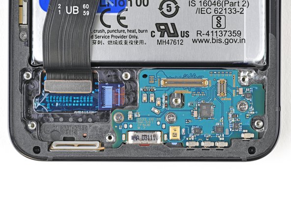
Tiny, delicate components are packed around this connector—think of them like the VIP crowd at a concert. Prying anywhere except the right spot could send them flying off the board. Take it slow and aim true!
- Slide the tip of your trusty spudger between the left side of the antenna press connector and the shiny shield on the motherboard.
- Gently pry it up and disconnect that antenna press connector like a pro!
Tools Used
Step 30
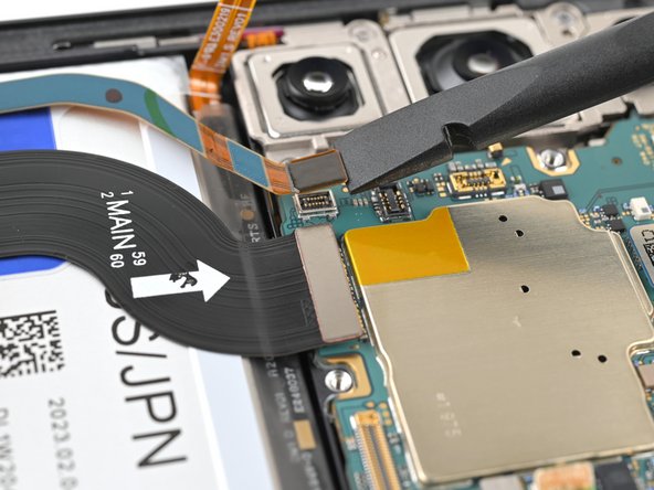
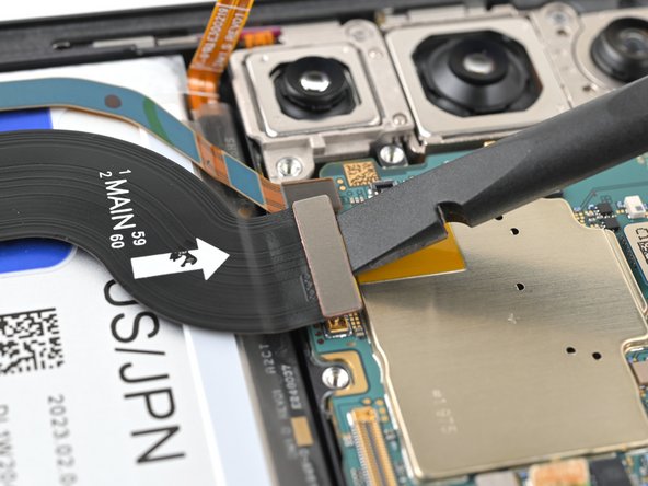

- Grab your spudger and gently pop the display and 5G mmWave cable connectors off the motherboard. Just a little wiggle and lift—they’ll come right up!
Tools Used
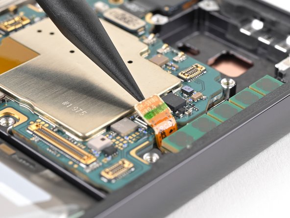
Step 31


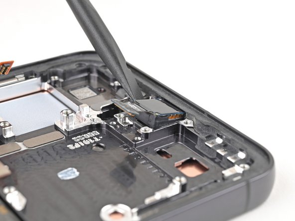
- Grab your spudger and gently lift to disconnect the front camera press connector. You've got this!
Tools Used
Step 32


- Grab a Phillips screwdriver and carefully remove the two 3.5mm screws holding the motherboard in place. It's a simple step, just a little twist and you're on your way.
Step 33


- Slide the flat end of your spudger between the top edge of the motherboard and the frame, right by the earpiece speaker cutout.
- Give the spudger a gentle twist to pop the motherboard up so you can grab it easily.
- Lift out the motherboard and set it aside.
- When putting things back together, make sure all the cables aren’t hiding under the motherboard before you drop it back into place.
Tools Used
Step 34


- Slip your spudger into the notch at the bottom edge, right where the top 5G mmWave antenna meets the frame—like sneaking into a secret club.
- Gently pry up and lift the antenna to break the adhesive’s grip. It might feel stubborn, but you’ve got this!
Tools Used
Step 35

- Gently wiggle the top 5G mmWave antenna out of the frame with your fingers, peeling off any stubborn adhesive as you go.
- When putting things back together, check if the conductive tape under the antenna needs to catch a ride to your new part.
Step 36

The adhesive holding the camera in place is seriously stubborn. Take it slow and add a bit more heat if the front camera refuses to budge—no need to force it. Make sure the circuit board stays connected to the camera housing.
- Warm up the front camera with a hair dryer or heat gun for about 90 seconds. Make sure it's nice and toasty, but don't overdo it! Just enough to loosen things up.
Tools Used
Step 37

If the camera is feeling a bit stubborn, grab your trusty SIM card eject tool and gently scrape away the epoxy around the camera. It'll help free it up in no time!
- Gently pop the front camera out of its little nook in the frame using the flat side of your spudger. Easy does it!
Tools Used

Step 38


- Grab your trusty spudger and gently pop the front camera up from its spot—just enough so you can get a good grip with your fingers.
- Lift out the front camera and set it aside like the VIP it is.
Tools Used
Step 39


- Gently pop up the display cable connector from the back of the screen using the flat end of your spudger—like you’re opening a stubborn pickle jar, but smaller.
- Slide that display cable out of the way. Nicely done!
Tools Used
Step 40

- Grab your trusty Phillips screwdriver and carefully remove the two 2.5mm screws holding the 5G mmWave antenna in place.
Step 41


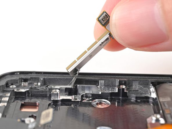
- Slip one arm of your trusty angled tweezers into a screw hole on the bottom 5G mmWave antenna bracket. Yes, really!
- Gently lever the bracket upward with your tweezers, just enough to grab it with your fingers and pull it out of its snug little spot. Smooth moves!
Tools Used

Step 42
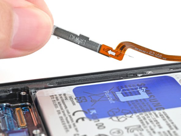

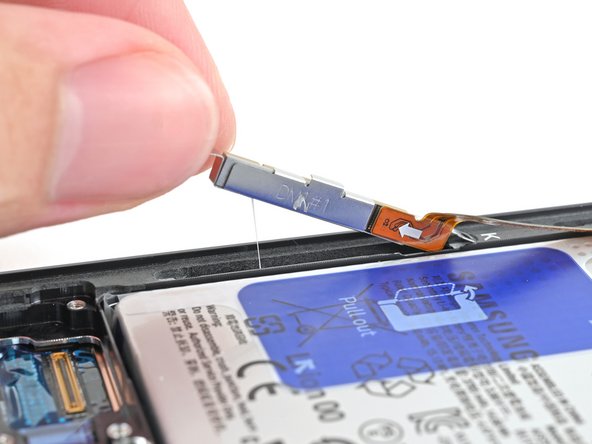
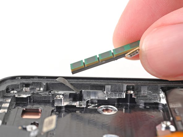
- Gently pop the bottom 5G mmWave antenna out of its spot to break the adhesive bond. No need for wrestling moves—just a little finesse.
- Now, whisk away the 5G mmWave antenna and give yourself a nod for a smooth extraction!
Step 43

- Ready to put things back together? Just retrace your steps and your device should be good to go.
- Don’t toss those old parts—drop them off with an R2 or e-Stewards certified recycler.
- Ran into a hiccup? Try some basic troubleshooting, or swing by our Samsung Galaxy S23 Answers Community for some tips.
- And hey, if you get stuck, you can always schedule a repair and let us handle the heavy lifting.