Samsung Galaxy S22 Screen and Battery Assembly Replacement
Duration: 45 minutes
Steps: 55 Steps
This guide focuses on fixing the screen and battery assembly. Let's get to work and give your device the TLC it deserves!
Ready to swap out the screen and battery assembly in your Samsung Galaxy S22? This step-by-step guide is all about the combo unit — that’s the screen, battery, and frame all in one piece. Double-check you’ve got the right part before diving in. Keep in mind, sealing up your device to keep water resistance intact depends on how well you reapply the adhesive, so don’t expect an IP rating to magically stay. If you need a hand, you can always schedule a repair.
Step 1


Oops! If you accidentally poked a micro-sized hole with the SIM eject tool, no worries—your microphone probably didn't take a hit. Just a little slip-up, and you're still good to go. If you need a hand with anything else, you can always schedule a repair.
- Grab your trusty SIM eject tool, a bit, or even a straightened paper clip, and slide it into the SIM card tray hole located on the bottom edge of your phone.
- Give that SIM eject tool a little push into the tray hole to pop out the SIM card tray like a pro.
- Carefully take out the SIM card tray and set it aside.
Step 2

Before you dive into this repair, let your phone's battery drop below 25%. A fully charged lithium-ion battery can be a bit of a fire hazard if things go south.
You can use a hair dryer, heat gun, or hot plate, but be sure to keep an eye on the heat—too much can spell trouble for your phone's display and internal battery. Let's keep them safe and sound!


Step 3


The adhesive likes to cling the most in the bottom right and top left corners, so focus your efforts there.
- While waiting for the adhesive to loosen up, keep in mind: there's a sticky grip holding the back cover around the edges of the frame.
Step 4


If the gap isn't happening, hit it with some more heat to loosen up that stubborn adhesive. Keep it cool—follow the iOpener instructions so you don’t overdo it.
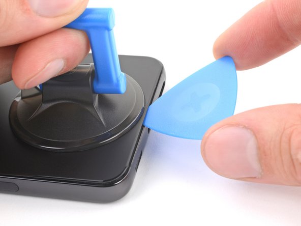
- Stick a suction cup near the bottom edge of the back cover, getting as close to the bottom as you can. No need to be shy—just make sure it’s firmly attached.
- Pull gently but firmly on the suction cup to create a small gap between the cover and the frame—think of it as giving the device a friendly nudge to start the separation.
- Carefully slide an opening pick into that gap to keep it open and continue the disassembly. Stay patient, and if you need a hand, you can always schedule a repair.
Tools Used

Step 5


- Glide the pick along the bottom edge, making sure to break up that sticky adhesive as you go.
- Keep the pick chilling in the bottom left corner—this keeps the glue from trying to make a comeback.
Step 6

- Warm up the left edge of the back cover with a heated iOpener for about two minutes. The goal is to loosen things up and make the next steps smoother.
Tools Used
Step 7


Slide the pick in just 5 mm—think of it like dipping a toe in the pool. Go deeper and you might wake up the antenna or power-button cables, and they’re grumpy sleepers.
- Time to get this repair started! Insert a second opening pick at the bottom left corner, and let's get that adhesive loosened up.
- Now, slide the pick down to the bottom of the camera bezel to slice through the left adhesive - you're making great progress!
- Leave the pick in place to keep that adhesive from resealing, and get ready for the next step in this repair journey.
Step 8

- Warm up your iOpener and give it a cozy spot on the right edge of the back cover for a solid two minutes. Let's get that adhesive nice and toasty!
Tools Used
Step 9


If the adhesive has made itself cozy again, slide that pick in closer to the bottom edge.
- Grab a third pick and gently insert it into the bottom right corner to start loosening things up.
- Carefully slide that pick up toward the top right corner, slicing through the adhesive along the way.
- Leave the pick in the top right corner to keep the adhesive from sticking back together. If you need help, you can always schedule a repair.
Step 10

- Warm up an iOpener until it's nice and pliable, then gently press it against the top edge of the back cover for about two minutes. This will help soften the adhesive for easier removal. If you need a hand, you can always schedule a repair.
Tools Used
Step 11


Be careful not to insert the pick more than 4 mm! Going too deep could damage the rear cameras or the flash. A little caution goes a long way!
- Pop an opening pick into the gap at the top right edge—like you're slicing into a perfectly wrapped present.
- Glide the pick along the top edge and curve it around the top left corner to gently break up the last bit of sticky adhesive.
Step 12


- Pop off the back cover and set it aside.
- While putting things back together:
- Now’s a solid moment to fire up your phone and make sure everything’s working before you seal the deal. Power it down fully again before moving on—no surprises wanted.
- If there’s leftover adhesive hanging around, grab some tweezers or use your fingers to clear it out. Stubborn bits? Hit them with some heat for easier removal.
- Ready for fresh adhesive? Follow this guide to lay it down right.
If your cover is still sticking to the frame, grab an opening pick and gently slide it around the edges until the cover pops free. Keep it slow and steady—patience is key to avoiding damage. If you hit a stubborn spot, don’t force it. Need a hand? You can always schedule a repair to get professional help.
Step 13


- Gently use the sharp end of a spudger to carefully detach the wireless charging coil from the motherboard.
To reconnect the press connectors, gently line them up and press down on one side until you hear it click into place, then do the same on the other side. Steer clear of pressing in the middle, as misaligning the pins can bend them and cause lasting damage. If you need a hand, you can always schedule a repair.
Tools Used

Step 14

- Grab your trusty Phillips screwdriver and get ready to tackle those six 3.5 mm-long screws holding down the wireless charging coil. It's time to show those screws who's boss!
Step 15

- Grab your Phillips screwdriver and gently remove the seven 3.5 mm screws holding the loudspeaker in place. Keep those screws safe—you'll want them when reassembling. When in doubt, if you need a hand, you can always schedule a repair for extra help.
Step 16


- Slide the pointy end of your spudger between the top left corner of the loudspeaker and the frame—like you're sneaking into a VIP section.
- Gently pop the loudspeaker up to unclip it from the frame. It might give a little resistance, but you've got this.
- When putting things back together, press all along the edge of the loudspeaker to snap those clips back in place. Nice and snug.
Tools Used
Step 17


Keep the charging coil and the loudspeaker buddy-buddies—don’t separate them! Keeping them together keeps things running smoothly.
- Slide that wireless charging coil and speaker out of the frame like you’re pulling the last slice of pizza—smooth and satisfying.
Step 18


- Take the pointy end of your spudger and gently pop up the battery press connector—like giving your device a little high-five for progress!
Tools Used
Step 19


- Grab your trusty spudger and use its pointed end to carefully lift up and disconnect both interconnect cables from the motherboard. You've got this!
Tools Used
Step 20
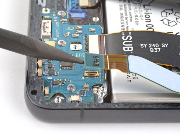
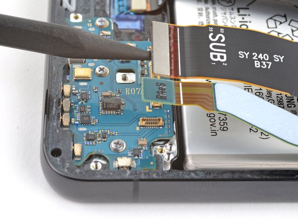

- Grab the pointed end of your spudger and gently pry up to disconnect both interconnect cables from the charging board. Take your time and be gentle—these connectors are delicate. If you need a hand, you can always schedule a repair.
Tools Used
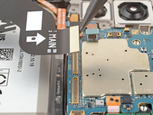
Step 21

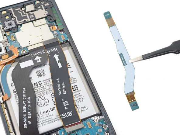
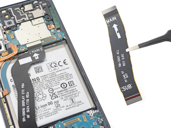
- Carefully disconnect the two interconnect cables from the frame. When putting everything back together, make sure the 'main' ends are pointing toward the top of the phone and the 'sub' ends are facing downward. Need a hand? You can always schedule a repair if things get tricky.
Step 22

- Grab your trusty Phillips screwdriver and take out the four 3.5 mm screws holding down the motherboard cover.
Step 23
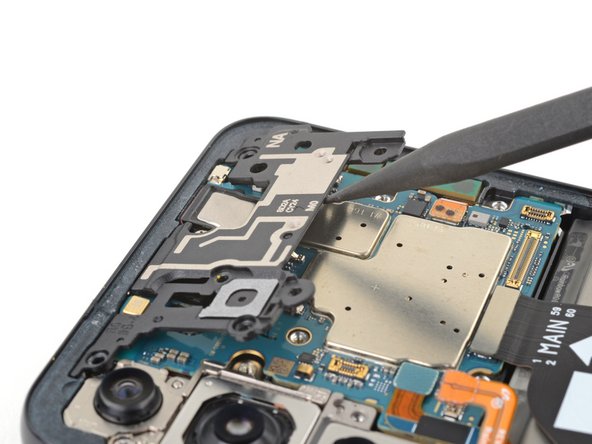

- Slide the sharp end of your spudger right between the bottom of the motherboard cover and the motherboard. It's like a little dance move!
- Gently lift the cover to pop it free from the frame. You've got this!
Tools Used
Step 24


- Carefully lift and take out the motherboard cover to get the party started.
Step 25
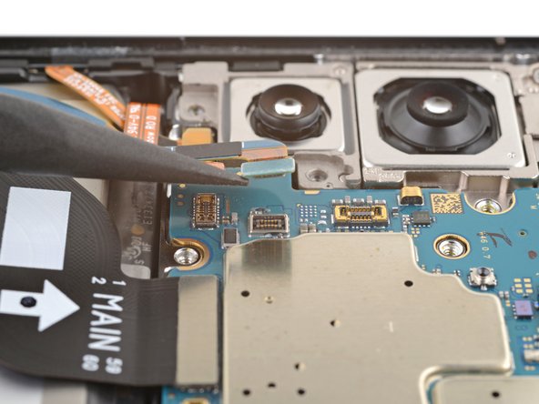

- Gently use the pointed end of your spudger to lift and disconnect the left 5G mmWave antenna press connector. You're doing great!
Tools Used
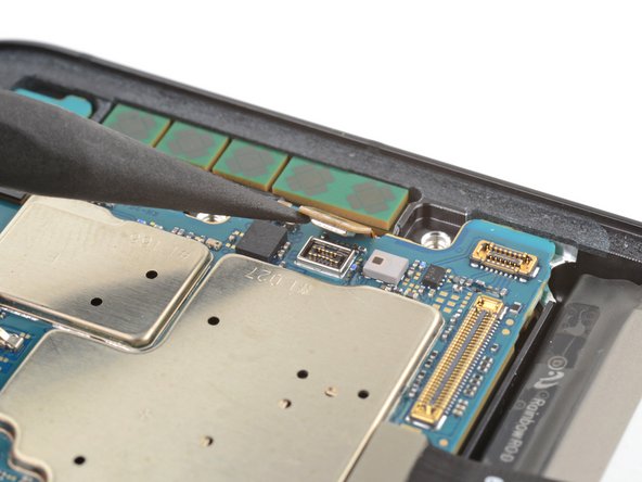
Step 26

- Grab the pointy end of your spudger and gently pop up that front-facing camera connector. Easy does it—no need to rush!
Tools Used
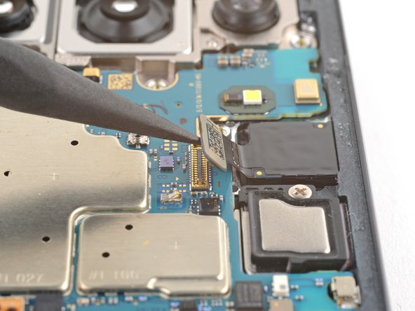
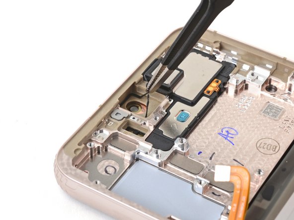
Step 27

- Take the pointy end of your spudger and gently pop up the screen press connector—like opening a secret latch.
Tools Used
Step 28

- Grab that pointed end of your spudger and gently pry up the right 5G mmWave antenna press connector to disconnect it. Easy does it—you're just teasing it loose like a pro. If you need a hand, remember you can always schedule a repair with Salvation Repair.
Tools Used
Step 29

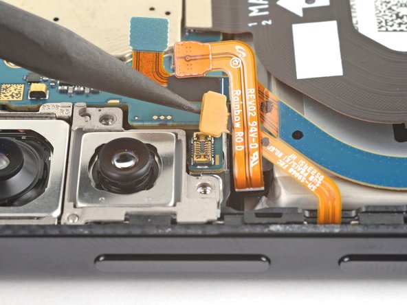
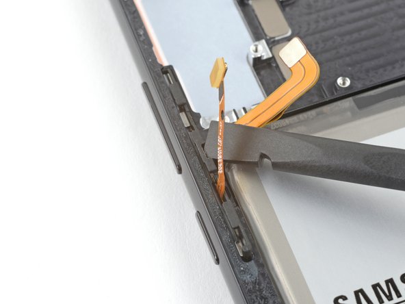
- Grab your trusty spudger and use its pointed end to gently pop up and disconnect the power and volume button's press connector. You're doing great!
- When you're putting everything back together, just keep in mind that this cable wants to hang out under the battery cable. It’s all about giving them the right space!
Tools Used
Step 30

- Grab your Phillips screwdriver and take out the 3.5 mm screw holding the motherboard in place. Easy does it—keep that screw safe for reassembly!
Step 31

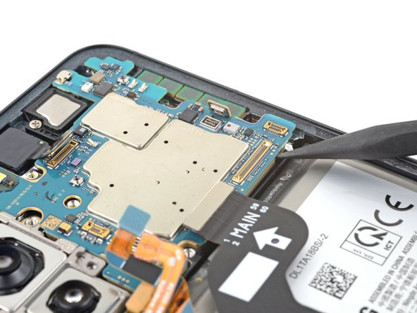
- Slide the pointed end of your spudger into the gap at the bottom right corner between the motherboard and the frame.
- Gently pry the motherboard upward until you can grip it with your fingers and lift it out.
Tools Used
Step 32
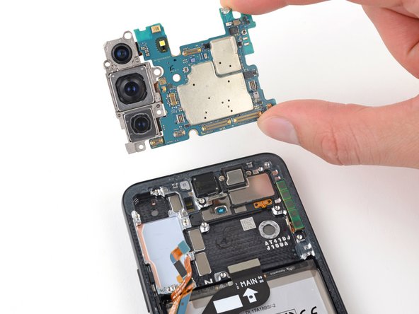

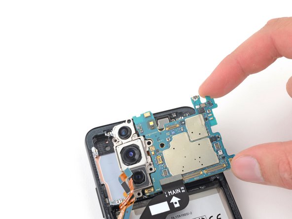
Watch out for loose cables — you don’t want to accidentally snag the motherboard. Keep things smooth and steady as you go.
- Pinch the right edge of the motherboard and gently lift—think of it as rescuing it from the frame.
- When you’re putting everything back, make sure the cables are lounging on top of the motherboard so it slides home like a champ.
Step 33

- Grab your Phillips screwdriver and take out those three 3.5mm screws holding the charging board in place. Simple as that!
Step 34
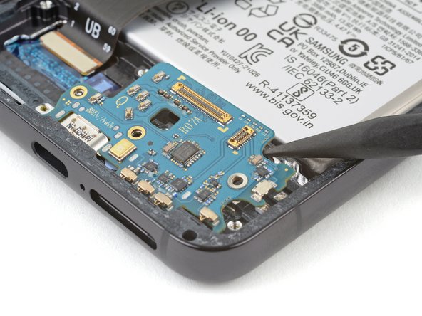

- Slip the pointy end of your spudger between the top right corner of the charging board and the frame—give it a little wiggle.
- Gently pop the charging board up until you can grab it with your fingers. Almost there!
Tools Used
Step 35

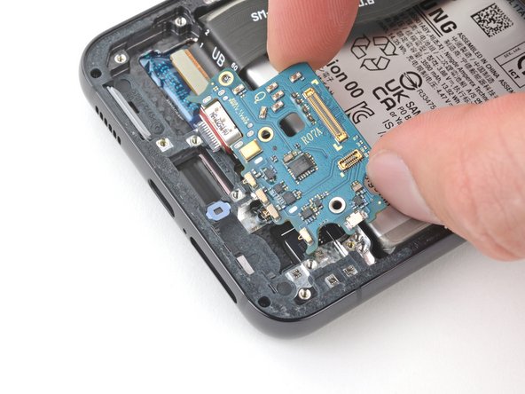
- Grab the charging board by its corners and gently slide it out of its cozy spot in the frame.
- Time to say goodbye to the charging board! Carefully remove it.
- When putting everything back together, angle the charging board downwards a bit to help the USB-C port find its place in the recess like it’s going home.
Step 36

- Grab your Phillips screwdriver and take out the two screws (they're 2.9 mm long) holding the earpiece speaker in place. Easy does it!
Step 37

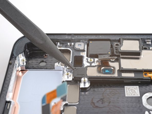
- Slip the pointed end of your spudger gently under the left edge of the earpiece speaker. Then, carefully pry upward to unclip the earpiece speaker from the frame. If you need help along the way, you can always schedule a repair.
Tools Used
Step 38

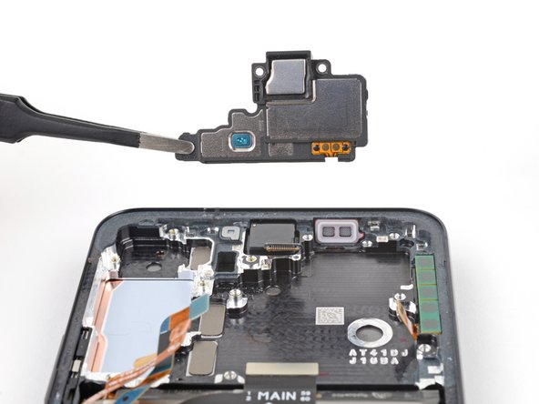
- Snag that earpiece speaker and pop it out with ease!
Step 39

- Grab your Phillips screwdriver and unscrew the pair of 3.5 mm-long screws holding down the lower 5G mmWave antenna. Easy does it—just a couple of turns, and you're good to go. If you need a hand, you can always schedule a repair.
Step 40

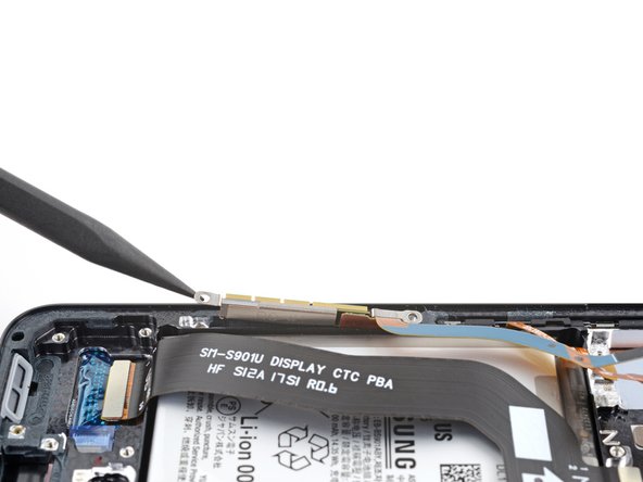
- Slide the pointy end of your spudger between the bottom screw mount of the antenna bracket and the frame—like you’re picking a lock, but less dramatic.
- Give the bracket a gentle lift until it’s loose enough to grab with some blunt tweezers or your fingers. No need for superhero strength.
- Take out the lower 5G mmWave antenna. Easy does it!
Tools Used
Step 41
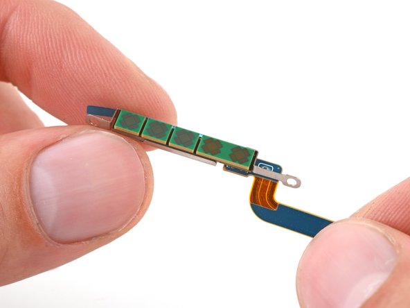

- Swap out the old bracket for a fresh one before popping in the lower 5G mmWave antenna—unless you're flying solo without a new bracket, then just skip this part.
- Gently pluck the antenna and connector out of the old bracket. No need to wrestle with it.
- Peel off the L-shaped adhesive liner from your shiny new bracket. It’s like unwrapping a tiny present.
- Nestle the antenna into the bracket’s recess, making sure the connector sneaks under the longer screw mount.
- Strip away the thin adhesive liner from the outside of the bracket, and then slide it into the frame like a pro.
Step 42

If the antennae is being stubborn, try warming it up with a heated iUpdatedOpener for a couple of minutes to loosen the securing adhesive, making it easier to!
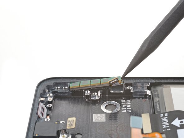
- Slide the sharp end of your spudger into the little gap between the upper 5G mmWave antenna and the frame. You've got this!
- Gently pry the antenna out of its snug spot until you can easily grab it with your fingers or some blunt nose tweezers. Keep it steady!
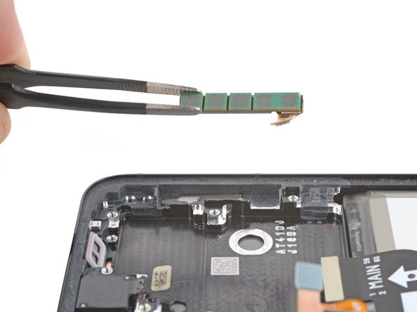
- Carefully take out the upper 5G mmWave antenna. You're doing great!
Step 43


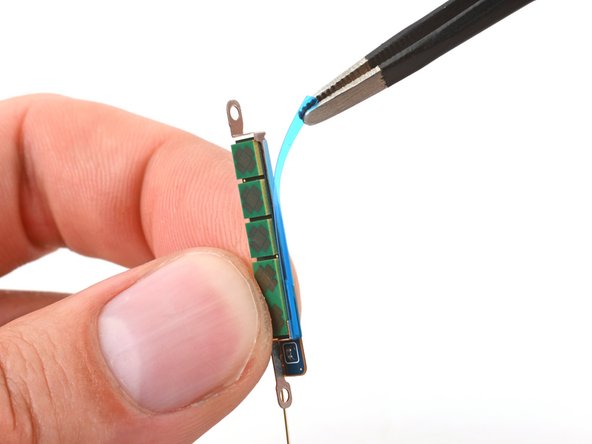
- Stick some fresh adhesive on that upper 5G mmWave antenna before you pop it back in. If you’re out of new adhesive, just reuse the old stuff or grab some custom-cut tape—no biggie.
- Peel off the old adhesive from the antenna using blunt nose tweezers or, hey, your fingers work just fine too.
- Take off the clear liner from your new adhesive—think of it like unwrapping candy, but for your device.
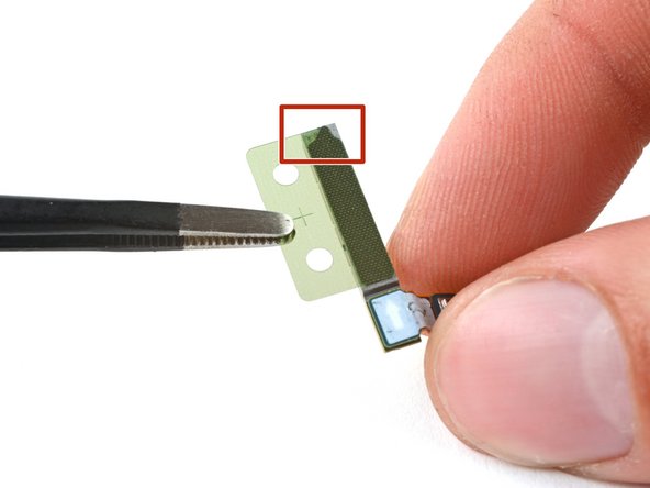
- Slap the new adhesive onto the bottom of the antenna, making sure the round end is furthest from the connector. Precision points if you get it lined up just right.
- Peel off the green liner before you slide the antenna back into the frame. And there you go, antenna ready for action!
Step 44

A hair dryer, heat gun, or hot plate can help, but watch out—too much heat can damage the display. Keep the heat level moderate and avoid overheating to keep your phone safe during the process.
Step 45
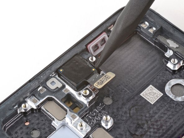

The adhesive holding the camera is pretty stubborn. Take your time, work gently, and if it feels like it's not budging, apply a bit more heat. Just be careful not to pull the circuit board away from the camera forcefully—patience is key here.
If the camera is feeling a bit stubborn, grab your trusty SIM card eject tool and gently scrape away the epoxy that's holding it back. You've got this!
- Grab the pointed end of your spudger and gently pop the front-facing camera out of its spot—like you’re giving it a little nudge to come out and play.
Tools Used

Step 46
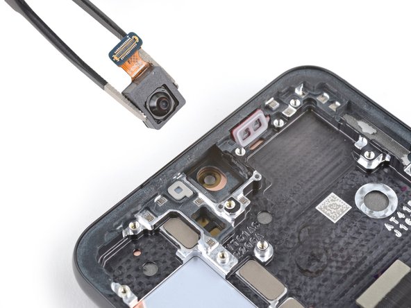

- Grab your trusty blunt nose tweezers and gently pluck out the front-facing camera from its snug little spot. Easy does it—you're just teasing it out of the recess.
Step 47

This part isn't needed for the repair.
- Alright, let's get your new frame ready for that front-facing camera! First up, peel off the black adhesive liner from the camera recess. It's like taking a sticker off, but way more exciting!
- Next, grab that foam liner from the new frame and give it a good peel. It's out with the old and in with the new! You're doing great!
Step 48

- Get ready to install that front-facing camera! First, swap out the old adhesive in the frame for a fresh one.
- Peel off the clear liner from the camera adhesive—think of it like opening a secret level.
- Pop the adhesive into the camera’s little nook, making sure the pull tab is chillin’ on the right side.
- Grab that blue adhesive liner and pull it away with the tab. Satisfaction guaranteed.
- Now, nestle the front-facing camera into its spot in the frame, and give it a gentle press so it sticks like it means it.
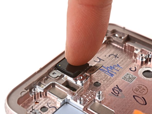
Step 49

- Grab your spudger and gently pop up the display cable connector—just give it a little lift, and you’re good to go!
Tools Used
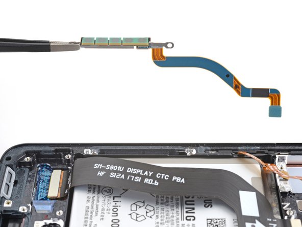
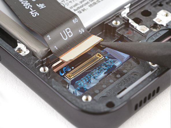
Step 50
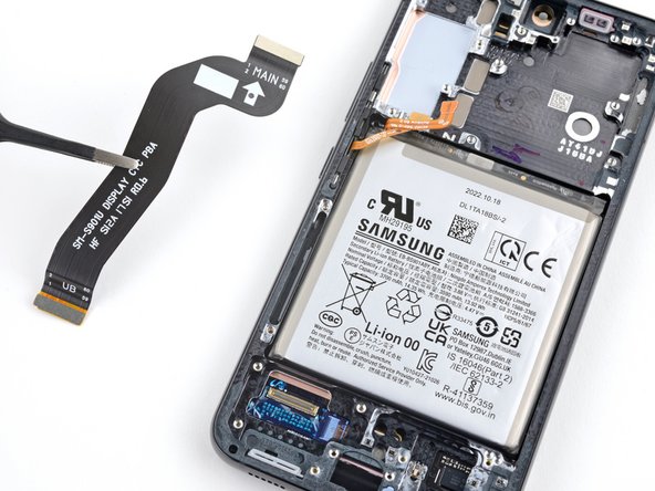

- Gently unplug the display cable from its cozy spot on the frame.
Step 51

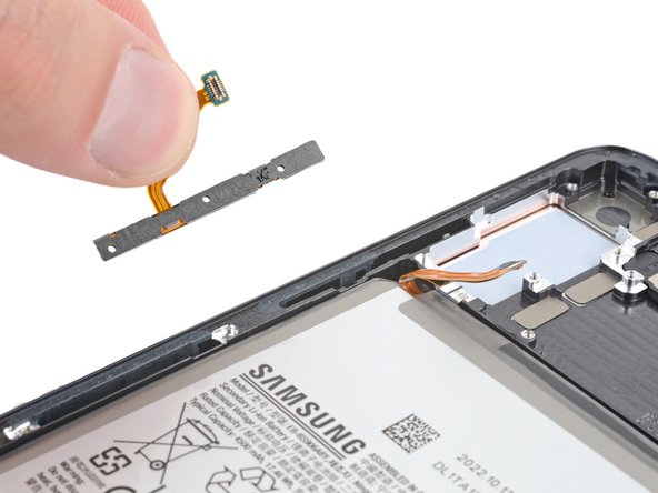
- Gently slide the corner of your spudger into the tab on the power and volume button bracket. It's like giving the tab a little nudge!
- Now, give the spudger a twist upwards to carefully pry the bracket out of its snug spot in the frame. Take it slow and steady.
- When putting things back together, press each button to make sure they snap into place with that satisfying 'click' sound. They should feel just like they did before you started.
Tools Used
Step 52
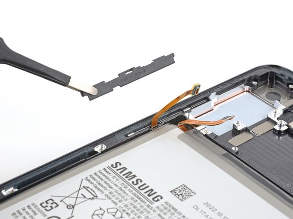

Heads up—sometimes the button pad likes to tag along with the bracket. No worries, just keep an eye out for that sneaky sidekick!
- Grab the power and volume button bracket using blunt nose tweezers or your fingers, then gently lift it out. Next, peel away the button pad with your fingers. When putting things back together, slide the button pad in first, then position the bracket against the back of the pad—together, they’ll fit snugly. Need a hand? You can always schedule a repair.
Step 53

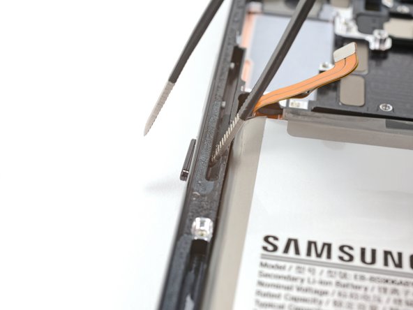
If your tweezers aren’t making the cut, grab a paperclip, bend the tip, and get in there like a pro. Sometimes you just need a little DIY creativity!
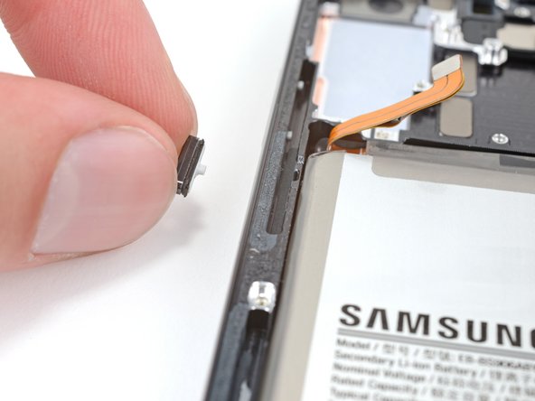
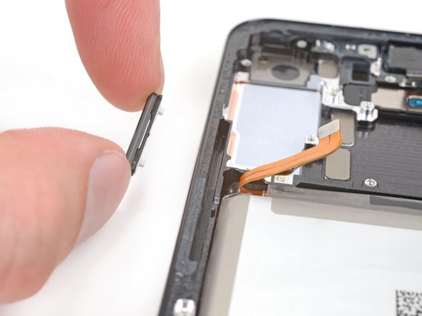
- Slide one arm of your trusty blunt nose tweezers into the cozy little recess of the power button.
- Give a gentle nudge to the power button's peg to disconnect it just enough so you can snag it with your fingers.
- Now, seize that power button and lift it out like a pro!
Step 54

If your tweezers can't quite reach, grab a bent paperclip or something similarly crafty to poke into the tight spot.
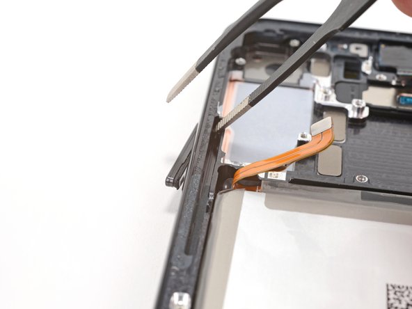
- Gently insert one arm of your blunt-tipped tweezers into the groove of the volume button.
- Press on both of the volume button's pegs simultaneously to loosen them from the frame, making it easier to grab the buttons with your fingers.
- Carefully use your fingers to lift out and remove the volume buttons.
Step 55

- Time to put everything back together! Just follow these steps in reverse, and you'll be good as new.
- Now that you're done, don't forget to responsibly recycle your e-waste with an R2 or e-Stewards certified recycler.
- If things didn't quite go as planned, don't worry! You can always schedule a repair or check out our troubleshooting community for some extra help.