Motorola Moto X Headphone Jack/Speaker Assembly Replacement
Duration: 45 minutes
Steps: 12 Steps
Time to swap out the upper midframe assembly of your Motorola Moto X, which packs in the headphone jack, the speaker, and the upper antenna. Follow along as you carefully detach and replace this crucial part, bringing your device back to life. Need a hand? You can always schedule a repair if things get tricky.
Step 1


If the SIM card doesn’t pop out of the tray easily, just use your fingers to gently pull it out. It’s a simple move, and you’ll be on your way in no time!
– Grab your trusty SIM card eject tool and carefully pop it into the tiny hole on the side of your SIM card tray. Give it a gentle push to eject the tray like a pro.
– Now that the tray is out, simply pull it out and set it aside. You’re almost there!
Tools Used

Step 2


Get ready to unlock your phone’s secrets. In the following steps, you’ll be releasing the clips that hold the phone’s cases together. Keep in mind that the back case is also secured with an adhesive pad, so be gentle. After you’ve separated the clips, you’ll use an iOpener to help the case open up completely. Remember, don’t try to fully open the phone before loosening the adhesive – we’ve got this, one step at a time.
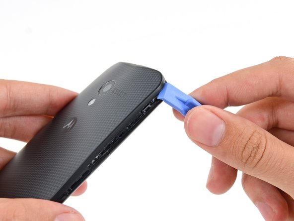
– Take your plastic opening tool and gently wedge it into the seam between the front and rear covers, right by the SIM card slot.
– Glide the tool along the edge, heading up toward the top corner.
Tools Used

Step 3

– Gently work the plastic opening tool around the corner, carefully loosening it from the clips.
Step 4


– Gently work your way around the top right corner of your phone, wiggling between the two covers to carefully separate them. Take it slow, you’re almost there!
Step 5


– Gently run the opening tool around the edges, working along all four sides to loosen those remaining clips that hold the cover in place.
The front cover’s plastic is a bit thinner around the buttons, so handle with care—press gently and go slowly to keep those buttons and the cover in good shape. Also, don’t push the opening tool too deep into the phone, or you might bump into some internal parts. If you need help, you can always schedule a repair.
Step 6

– Warm up an iOpener and gently place it over the phone for about 90 seconds to soften up the adhesive holding the back cover in place.
Tools Used
Step 7


The NFC coil might cling to the back cover a bit too tightly. If that’s happening, take a breather, stop peeling, and heat up your iOpener again to give the back cover some extra warmth.
Don’t go all the way just yet! The back cover is still hanging on by the camera flash cable, so leave it attached for now.
The back cover is quite bendy, but take it slow—no rushing or you might harm those sneaky internal parts. Also, keep in mind that the flash cable is tucked on the power/volume button side of the phone. Handle with care, and if things get tricky, you can always schedule a repair.
– Begin by gently peeling off the back cover, starting from the SIM slot side. Take it slow, no need to rush, and you’ll have it off in no time.
Tools Used
Step 8

– Gently lay the back cover down so the camera flash cable connector is nicely exposed, but without putting any stress on it. Take your time and handle it carefully—no need to rush. If you need help, you can always schedule a repair.
Step 9


When prying, be gentle and focus on the flap itself – avoid putting any pressure on the connector to prevent damage.
– Grab your trusty spudger and use its tip to lift the retaining flap on the flash cable ZIF connector.
– Once it’s popped up, gently pull the flash cable straight out of its socket.
Tools Used

Step 10

– Carefully peel the back cover away from the phone. Give it a gentle nudge, but don’t rush it—this part just takes a little finesse.
Step 11

– Start by removing the five 3 mm T3 Torx screws holding in the headphone jack and speaker assembly. Don’t forget, if you need a hand with this, you can always schedule a repair.
Step 12


– Time to get this repair started! Carefully insert a spudger under the panhandle of the headphone jack/speaker assembly and gently pry it up from its recess.
– Now that it’s loose, go ahead and remove the headphone jack/speaker assembly.
Tools Used
Success!