Vizio VTAB1008 Charging Port Replacement
Duration: 45 minutes
Steps: 9 Steps
Hey there! Ready to tackle the fun task of swapping out the charging port on your Vizio VTAB1008? Let’s dive in and get your device powered up again! If you need help, you can always schedule a repair.
Step 1


Careful now! Don’t go poking too far in with the opening tool—it’s a tight space near the edges, and those connectors don’t appreciate getting roughed up.
Here’s the trick: use the angled tip of the opening tool like a pro. Press the back of the tool with your thumb for grip, then slide it smoothly to pop those tabs free—easy does it!
– Grab that heavy-duty opening tool and ease it into the gap on the button-free side—nice and steady, no rush!
– Those corner tabs can be stubborn, so if they refuse to budge, grab the metal prying tool and work those corners with a bit more persuasion. Just be gentle—you’re separating tabs, not breaking into a vault!
Step 2

You’ll find three cheeky little connectors hanging out: one for the screen, one for the digitizer, and one for the motherboard. They’re snug and secure thanks to the cozy embrace of the backing and screen assemblies.
– Check inside the tablet for any loose connectors that might be causing trouble.
– Carefully flip the backing from the side without buttons, making sure not to disconnect the ribbon connector from the display screen.
Step 3


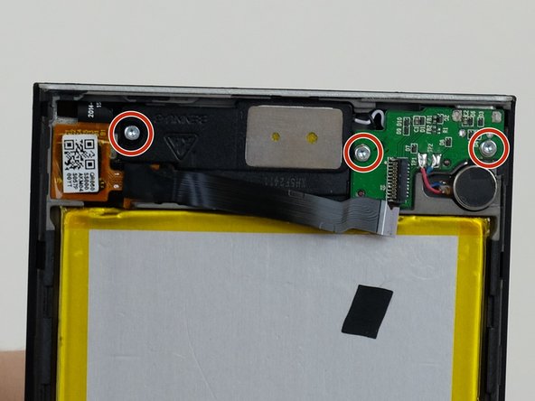
Three of the screws are easy to spot, but the fourth one is playing hide-and-seek behind some black tape on the upper left corner of the motherboard. Keep your eyes peeled!
– Carefully take out the motherboard by loosening the four screws that hold it in place using a J1 Phillip’s head screwdriver. You’ve got this!
Step 4


– Gently pop off both antenna connectors using a blue opening tool or tweezers—easy does it!
Tools Used

Step 5

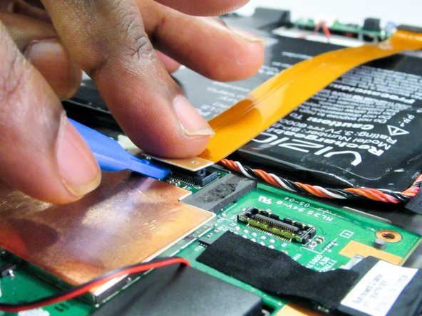
– Carefully detach the ribbon connector located at the top of the motherboard using your trusty opening tool. You’ve got this!
Step 6

– Gently detach the connector sitting atop the motherboard—whether with your trusty fingers or a pair of tweezers, give it a smooth pull straight away from the board.
Tools Used
Step 7


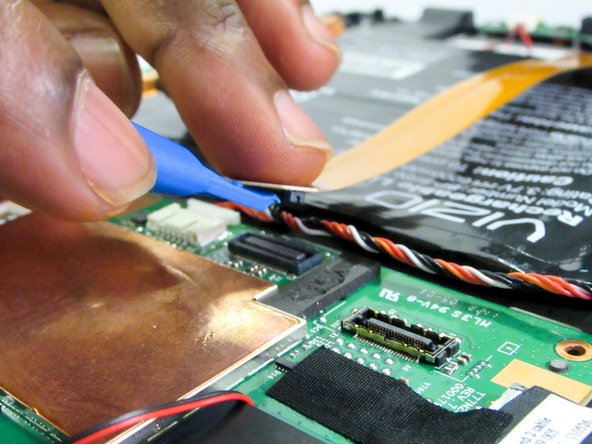
You’ll find the connector snugly wrapped up in a layer of black tape.
– Gently pry off the connector on the side of the motherboard using your trusty opening tool.
Step 8

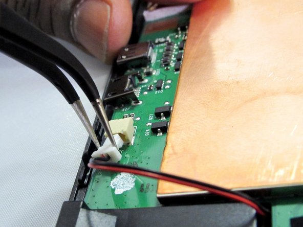
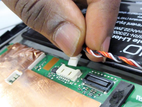
– Gently detach the red and black wire connector from the motherboard. You can use your fingers or tweezers for this little task. You’ve got this!
Tools Used
Step 9


– To get your device back in working order, simply follow these steps in reverse. Easy peasy!
– You’re almost done! If you need help or want to leave the repair to the pros, you can always schedule a repair.