Viewsonic gTablet UPC300-2.2 LCD Screen Replacement
Duration: 45 minutes
Steps: 9 Steps
Step 1


Stay cool! These little guys are glued in tight, so it might take a few tries and a bit of time to pop them out.
– Grab your trusty spudger or metal tweezers and gently pop those rubber screw covers out of their cozy little spots at each corner of the back cover.
– Now, with your PH00 screwdriver in hand, let’s tackle those 5.8mm screws hiding beneath each rubber cover (that’s four screws in total).


Step 2


Be careful not to push the prying tool in too deep while separating the back cover. You don’t want to accidentally mess up any other parts! Take it easy, and if things get tricky, feel free to schedule a repair.
– Grab your trusty prying tool and gently coax the back cover away from the gTabet. You’re doing great!
– Start at the charging port and make your way around the device’s edge in one smooth motion. Keep it steady!
– Carefully lift off the back cover to unveil the inner workings of your device. Nice job!
Step 3

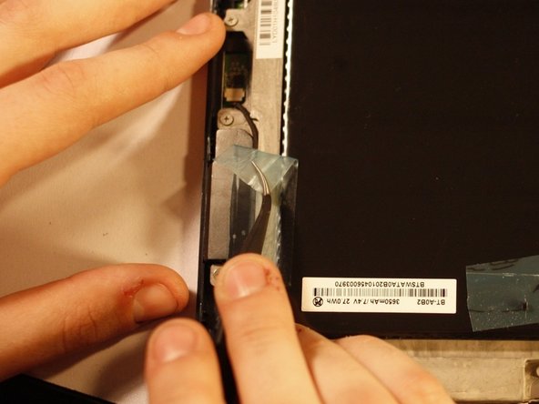
– Look for the big black square—yep, that’s your battery! It’s the star of the show inside your device.
– You’ll find some tape keeping a few wires snug and secure. Time to say goodbye to that tape before we can free the battery. Just peel it off gently; you’ll want to keep it around for later!
Step 4
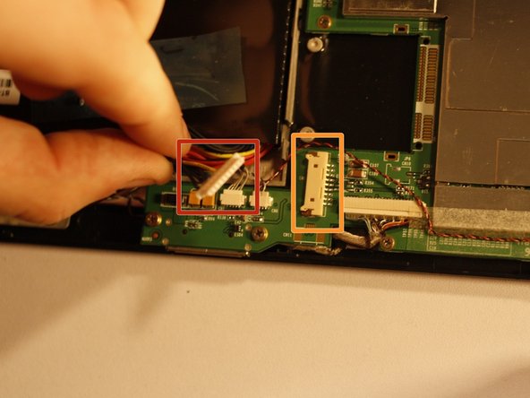

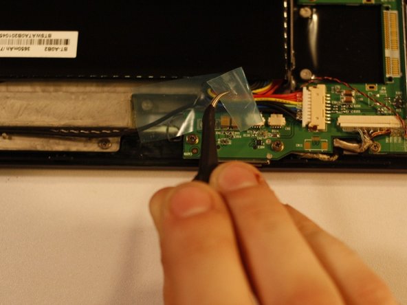
The white connector (marked in red) pops off, while the off-white connector (marked in orange) stays cozy on the motherboard.
– Grab a PLASTIC tool—nothing metal, okay?—and gently press on both ends of the power cable connector, one side at a time. Ease it away from its housing with a little back-and-forth motion, like you’re coaxing it out of a comfy seat. Patience is key! It’ll wiggle free soon enough.
Step 5


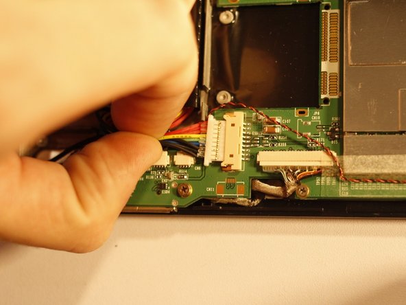
Before you dive into moving that battery, make sure to clear any wires out of the way! They’re still connected and we don’t want to put them under any stress – they deserve a break too!
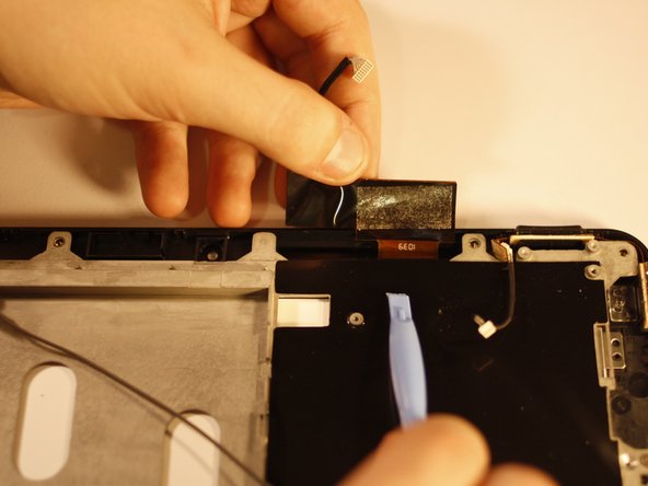
– Grab those tweezers and gently peel away the protective foam backing from the front-facing camera.
– Carefully wiggle the camera out of its snug little home and set it aside for now.
– With a soft touch, lift the battery up and away from the device, then place it somewhere safe.
Tools Used
Step 6

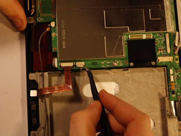
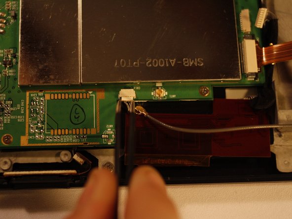
– First up, let’s unplug that LCD Video cable. You’ll find it chilling to the right of the battery power housing. If you need a little extra grip, feel free to use pliers on this big connector, but be gentle!
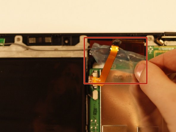
– Next, we’ve got two more connections to release before we can keep cruising. The first one is located to the right of the front-facing camera housing on the motherboard. It’s a tiny fella, so treat it with care!
– Now, look for a similar connection next to the antenna connection on the motherboard, diagonally from the one you just unplugged. You got this!
– And there you have it! All the necessary wires are now disconnected, and the motherboard is ready to be safely removed. If you need help, you can always schedule a repair.
Step 7

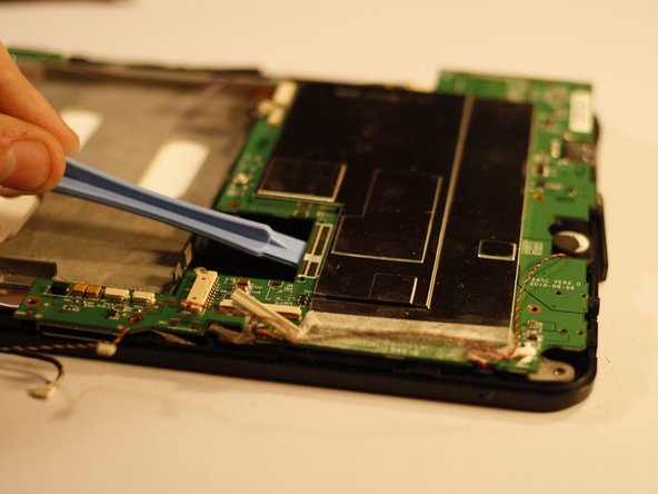
Heads up! You’ve got a couple of sneaky screws in the mix. Most of them are 3.3mm, but watch out for the oddballs: 5.9mm (orange) and 5.7mm (yellow). To keep your workspace tidy and organized, it’s a great idea to create a ‘Motherboard Pile’—a special spot for those screws that are essential for securing the motherboard.
– There are 8 screws holding the motherboard snugly to the chassis—time to loosen those up.
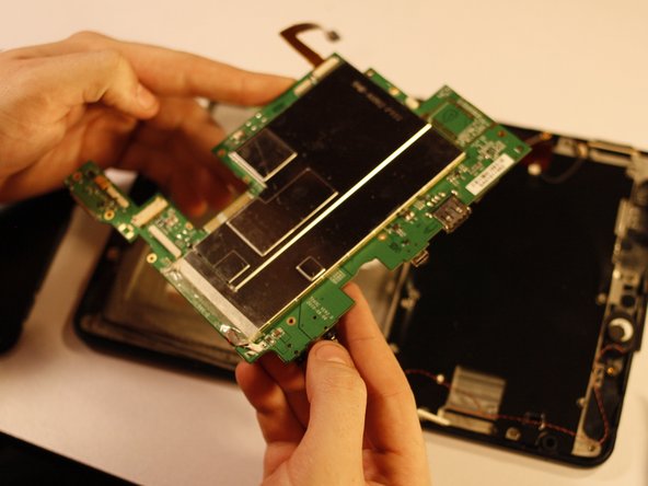
– Carefully lift the motherboard away from the device. If you have an anti-static bag, pop it in there for safekeeping. Otherwise, avoid setting it down on static-prone surfaces like fabric or metal.
Step 8

Just like with the other screw sets, it’s a great idea to keep these little guys in their own spot. This way, you’ll steer clear of any screw mix-ups later on!
– There’s a sneaky circuit board stuck to the back of the LCD chassis (the rear cover), and it needs to be removed before you can unscrew the chassis. It’s like a secret hiding place, so make sure you get it out of the way first.
– The adhesive holding this component is pretty strong, so take it slow and steady as you carefully work the plastic cover off. Use a spudger, and gently pry it up in small steps. With a little patience, it will come off without any hassle.
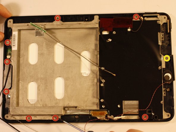
– Now, let’s get the chassis of the LCD screen off. Grab your trusty PH00 screwdriver and unscrew the 6 screws (4.5mm) around the edge of the chassis. One of the screws, marked with yellow, is a special case — it won’t come out all the way. Just loosen it and move on!
Tools Used
Step 9
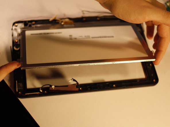
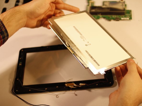

When you take out the LCD, the video cable should still be connected. In this case, it’s missing. Don’t worry though—if it gets accidentally detached like this one, it’s super easy to reconnect. Just a quick fix and you’re back on track!
– Gently detach the LCD Chassis. Oh, and keep an eye on that antenna and its wire—they’re in it for the long haul!
– Carefully lift the LCD screen from the ‘top’ of your device (that’s the longer side with the front-facing camera). There’s a sneaky little piece of double-sided tape down at the bottom holding it snug; just keep lifting to set it free!