How to Fix iPhone XS Unresponsive Touch Screen
Duration: 45 minutes
Steps: 5 Steps
Step 1


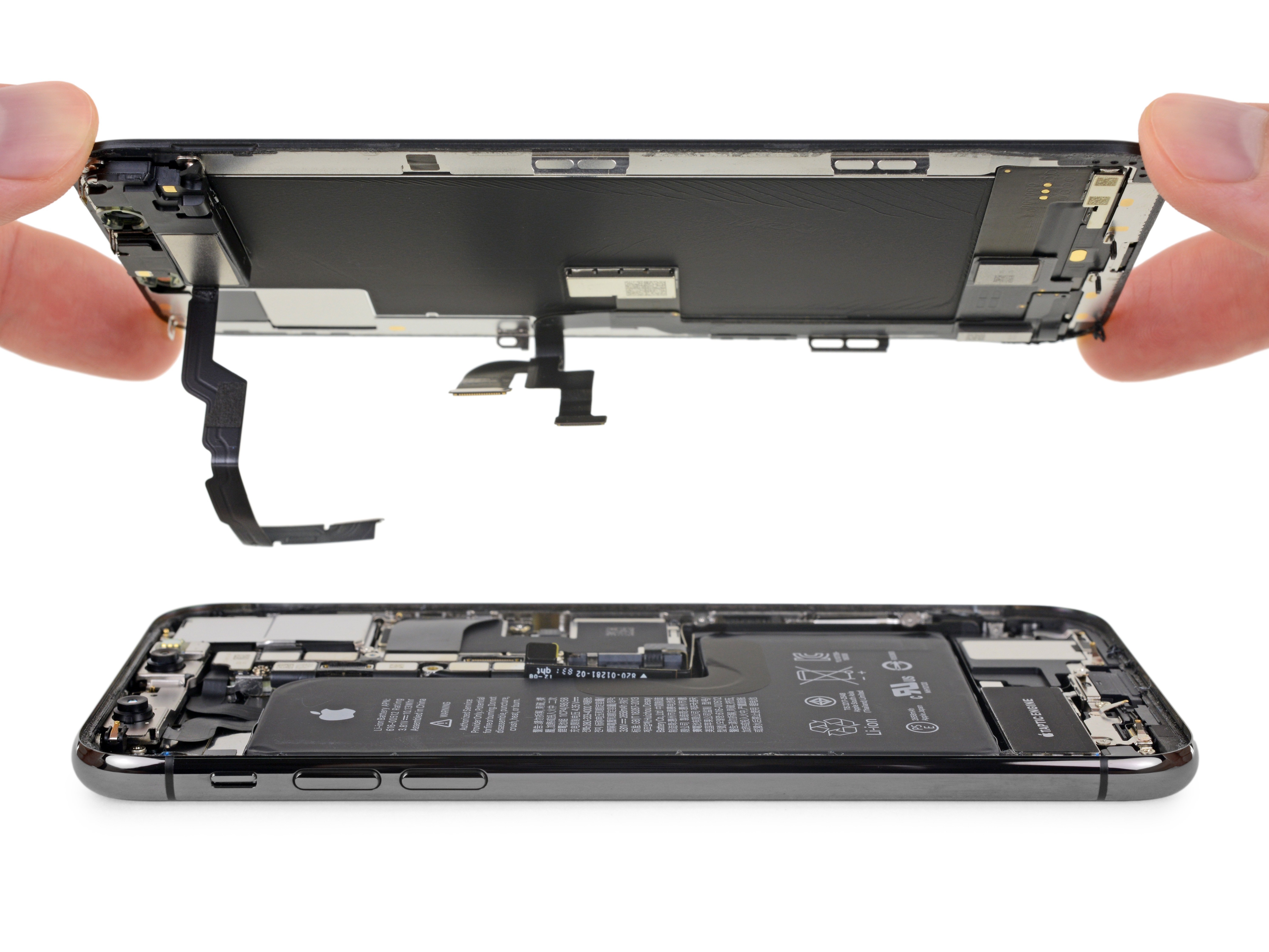
- Let's kick things off by inspecting the motherboard. Make sure it's free from any warping or water damage—everything should look neat and tidy.
- Now, let's pop the motherboard back in for a quick test. Hook up the display and the battery, power up the phone, and...oops, looks like the touchscreen's taking a nap.
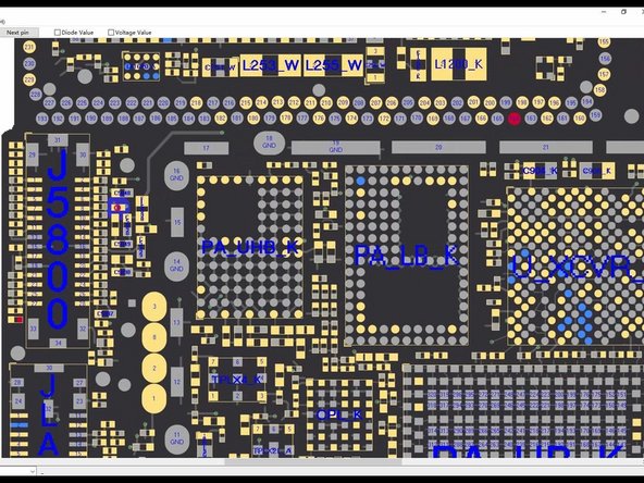
- Next, we check out the touch connector. We find that pin 21 isn't making a connection—this is where the problem lies. It seems the circuit linked to pin 21 is having a bad day.
Step 2


- First, let's open up the bitmap. Pin 21 is wired to resistor R5842, which is a safety resistor, so both ends should be connected. Take a moment to check the resistor and see if it's still in good shape.
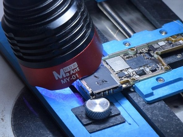
- Now, grab the motherboard and secure it in place. Use a hot air gun set to 260°C with airflow at 2 to soften the black adhesive and get rid of it.
- Time to break out the multimeter and do a quick check. The resistor checks out fine, so it’s not the culprit here. Looks like the issue is hiding somewhere in the middle layer of the circuit.
Step 3


- First up, let's give that motherboard some space! Place it on the 160 °C Heating Platform and let it soak up the warmth for about a minute. Once that's done, grab your tweezers and delicately lift away the logic board and signal board. Ta-da! The motherboard is now separated.
- Now, it's time to check out the bitmap. You'll find that the other end of the resistor is linked to the power IC via the middle layer. So, let's roll up our sleeves and measure the circuit on the logic board first. If the resistance value looks good, we're golden!
- Next, we need to measure the circuit between the signal board and the touch connector. Drumroll, please... The resistance value should show up as 1. And that's it! You're doing great!
Step 4


- It looks like we’ve got an open circuit on our hands! No worries, let’s jump right in and make it work. First, we’ll need to add a little Paste Flux to the resistor. Then, grab your trusty Soldering Iron set to 360 °C and solder that copper wire right onto the resistor!
- Since those two ends are playing hard to get, let’s secure that copper wire first. Apply some Solder Mask to keep it in place, then solidify it with a UV Lamp. Give it a little check with tweezers to see if it’s all set. Now, let’s take care of the other copper wire with some more Solder Mask!
- Time to cut that copper wire! Solder one end to the signal board and whip out your multimeter for a quick check. If you see a resistance of 0, you’re golden – that means the circuit between the touch connector and the signal board is good to go! Now, solidify those pads on the signal board with Solder Mask, scrape them to reveal the pads, and give those bonding pads a nice clean with PCB Cleaner.
Step 5


- Ready to wrap things up? Just work your way backwards through these steps to put your device back together. If you hit a snag, you can always schedule a repair for a quick rescue.
-