
Repair an iPhone X That Won’t Charge
Duration: 45 minutes
Steps: 11 Steps
Step 1


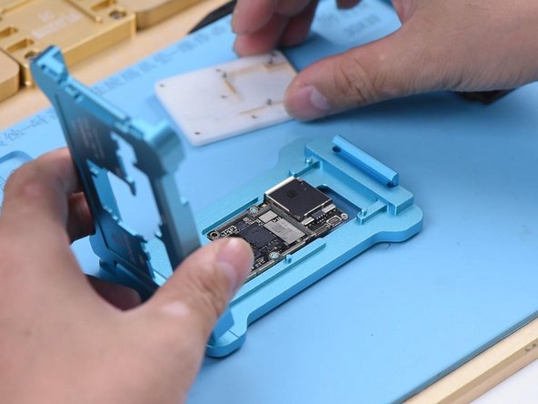
Looks like the motherboard is giving a thumbs up to the power adapter, but unfortunately, the phone is just not feeling the charge. No worries, we've got this!
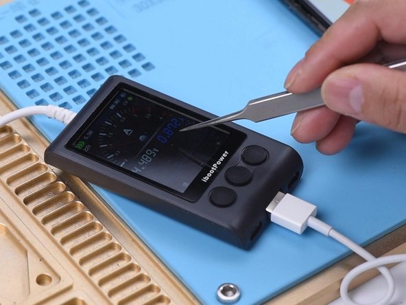
- Alright, let's pop that motherboard in and give it a quick test. The phone powers on just like it should.
- Plug in the charger and you’ll see the lightning bolt icon pop up. But heads up—the ammeter shows there’s no charging current flowing.
Step 2


Alright, since we’ve got good-to-go parts for the housing, battery, and charging port flex cable, let’s zero in on the charging circuit on the motherboard. Time to dive deep and get this fix rolling!
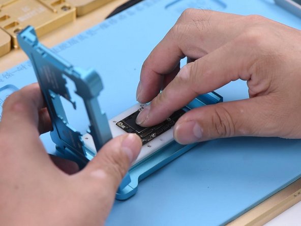
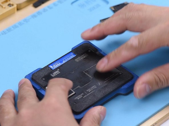
- Alright, let’s get started by separating the upper and lower layers. Place your motherboard on the heating platform and fit a screw into the hole on the motherboard. This way, we’ll be ready to remove the upper layer easily when it’s time.
- Now, give your motherboard a quick 2-minute heat session on the platform at 165℃. Let the heat do its magic and soften things up for a smooth repair.
Step 3


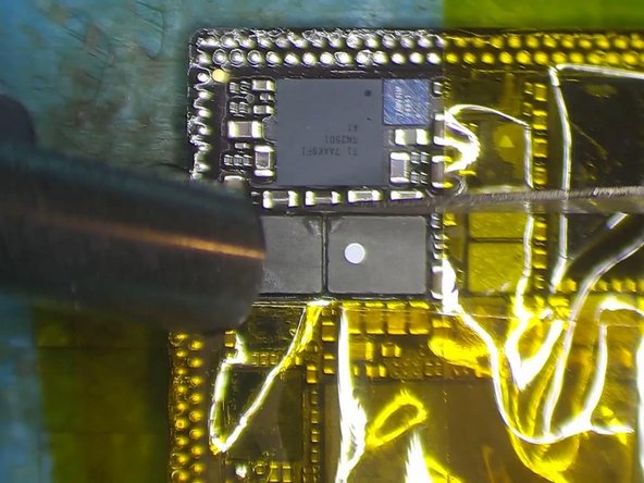
- Pop your multimeter into diode mode and test Pin 2 and Pin 3 on battery connector J3200. If your readings look normal, you’re off to a good start.
- Next up, check TIGRIS_LX between charging IC U3300 and Q3350. If the reading is 250, that’s not what we want—it should be 0. Looks like TIGRIS_LX has gone on vacation and left an open circuit behind.
Step 4


L3341 and L3340 are linked together in series in the circuit. If the connection is open, it usually means these two inductors have either been poorly soldered or damaged. Time to swap out the faulty inductors with new ones. If you're unsure or need a hand, feel free to schedule a repair.
- First up, let's get that upper layer snugly attached to the PCB holder. Don't forget to use some high-temperature tape to secure those components around it—safety first!
- Time to bring out the heat! Grab your QUICK 990AD Hot Air Gun, set it to a cozy 300℃ with an airflow of 3, and let the magic happen.
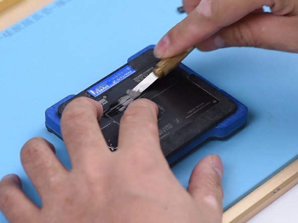
- Next, we need to bid farewell to the black adhesive that’s hanging around the two inductors. A clean workspace is a happy workspace!
- Once that’s taken care of, let’s add a little love with some paste flux on those two inductors. Crank up the heat again with the Quick 990AD Hot Air Gun, this time to 360℃ and airflow of 3, and watch the wonders unfold!
Step 5
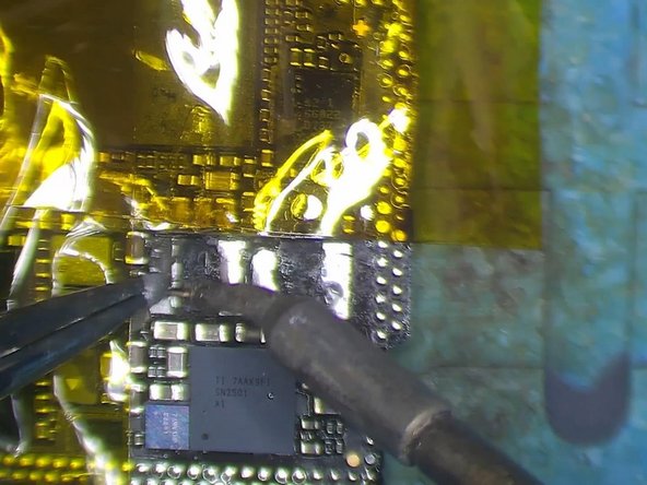

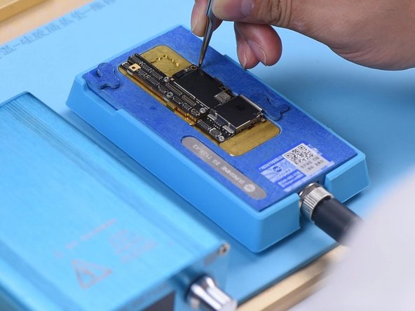
- Gently lift the two inductors using your pry knife—easy does it!
- Next, spread some medium-temperature solder paste onto the two bonding pads. Then, carefully tin those pads with your soldering iron set to 365℃.
- Finally, clean off any black adhesive lingering on the bonding pads to keep things tidy.
Step 6


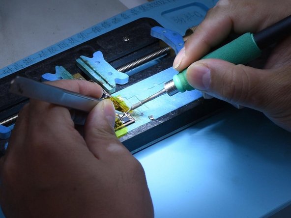
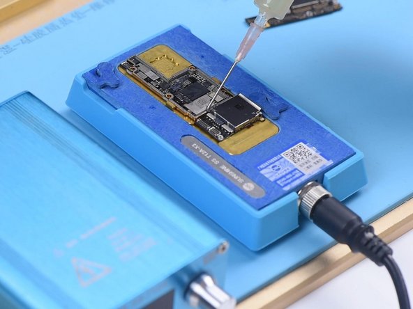
- Apply a little more paste flux to those bonding pads to keep things moving smoothly.
- Position the two inductors just right, then grab your trusty QUICK 990AD Hot Air Gun. Set it to 360℃ and airflow 3, and solder away with ease.
- Once you're done, clean up with a PCB cleaner. Now, let’s check out the diode mode measurement of TIGRIS_LX between U3300 and Q3350. It should read 0 – that's totally normal!
Step 7

- Alright, it's time to bring together the upper and lower layers with the testing fixture for a little quality check! First things first, give that bonding pad a good clean.
- Next up, let's get those layers connected to the testing fixture. You're doing great!
Step 8
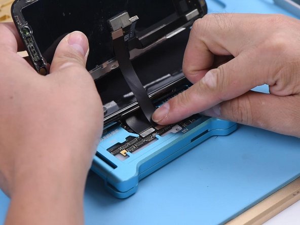

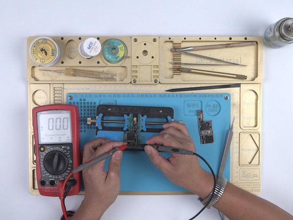
- First, connect the charging port flex cable with care.
- Next up, hook up the screen and battery to get things powered up.
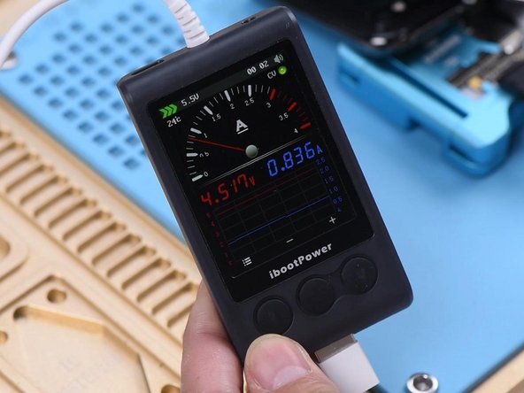
- Finally, plug in the charging cable. If your ammeter reads around 860mA, congrats—that means your phone is charging just right!
Step 9

- All right, time to get those two layers to stick together! First, let's give the lower layer a fresh set of solder balls. Pop it into your reballing mold and line up the BGA Reballing Stencil over it.
- Set the mold on the base—the magnetic setup keeps everything snug. Now, spread some low-temp solder paste over the stencil. Wipe off any extra paste with a lint-free wipe, and you’re good to go!
Step 10

- Once you've reballing done, carefully lift the mold off the base and remove that reballing stencil. Set the lower layer on the heating platform at 165℃ and let the magic happen. Once the solder balls are fully formed, turn off the heating platform.
- Let it cool for 5 minutes—patience pays off! Now, add a bit of BGA Paste Flux to the bonding pad and get that upper layer into position.
- Power the heating platform back on, and bring the temperature back to 165℃. Keep it heating for another 2 minutes to make sure everything’s set.
Step 11

- Power down and give it a cool 5-minute break. Then carefully lift the motherboard off the heating platform. Take a close look to ensure those two layers are soldered together just right.
- Time to put it all back together and see if it’s working! Reinstall the motherboard and reconnect the display assembly.
- Plug in the charging cable. If you see the lightning bolt on the screen and the ammeter shows a normal charging current, you’re all set—the issue is fixed!


