
iPhone X Wireless Charging IC Replacement
Duration: 45 minutes
Steps: 10 Steps
Step 1


- Start by giving the motherboard a quick once-over. Make sure it’s looking good — no bends, no water spots, just a solid, healthy board.
- Next, it's time to put everything back together and do a quick test to check that it’s all in working order.
- Press the power button and see what happens. If it powers on without a hitch, you're all set!
Step 2


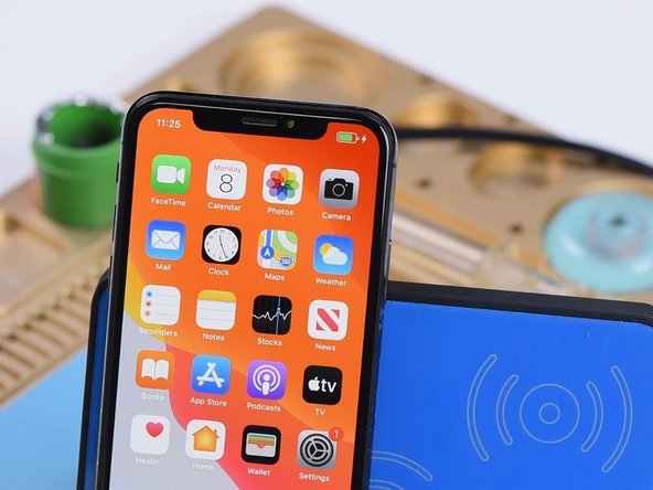
- First things first, plug in that charging cable. Your phone is ready to soak up some power.
- Want to skip the cords? Place your phone on the wireless charger. But just a heads-up, if your phone doesn't support wireless charging, it won't work here.
- Let's zoom in on the wireless charging circuits. These are the little guys that make the magic happen.
Step 3


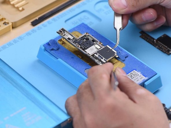
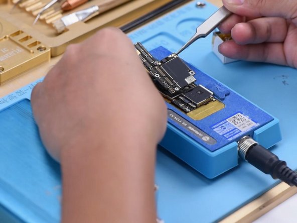
- Pop open your phone and gently lift out the motherboard. First, peel off that dust-proof sponge sitting on top—it’s just hanging out there, blocking our way.
- Get your multimeter ready for diode mode and check out the wireless charging connector. Normal readings mean the top-side wireless charging circuits are in good shape. Now let’s dig a little deeper and check out the circuits below.
Step 4

- First up, let's separate the top layer from the bottom layer! Pop that motherboard onto the heating platform and snug a screw into the screw hole on the motherboard. This will make it super easy to remove the upper layer later on.
- Next, it's time to give that motherboard a warm hug for 2 minutes at 165℃ on the heating platform. Just enough to get it nice and toasty!
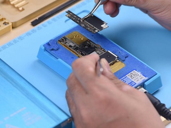
- Once it's heated up, grab your tweezers and gently lift off the upper layer, followed by the lower layer. You're doing great!
Step 5

- Take a good look at the lower layer to make sure everything’s looking sharp and nothing’s out of place.
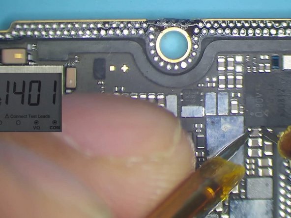
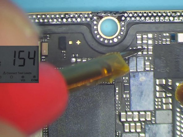
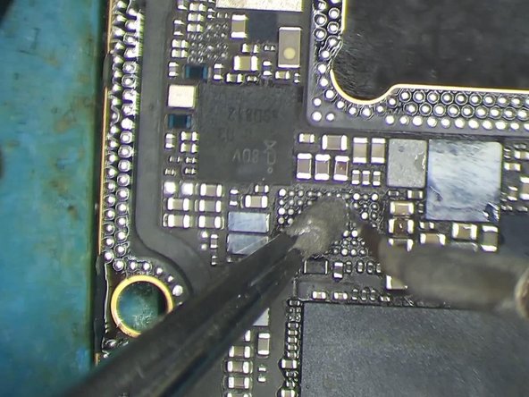
- Switch to diode mode and check the capacitors around the wireless charging IC. The readings show no signs of shorts, so all clear here.
- Keep going with diode checks around the wireless charging IC. The numbers look good, so no issues detected.
Step 6


- Alright, let's swap in a fresh wireless charging IC and see if we can get things buzzing again.
- Secure the lower layer onto the PCB holder and spread a little paste flux on the wireless charging IC to get things ready.
- Use the QUICK 990 AD Hot Air Gun set to 360℃ with airflow at 3 for about a minute. Carefully lift the wireless charging IC off the board using tweezers.
- Next, apply some medium-temp solder paste to the bonding pad. Clean it up nicely by heating with a soldering iron at 365℃.
Step 7


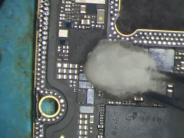
- Crank up the Hot Air Gun to 360℃ with airflow set to 3, and gently glide over the bonding pad using rosin-soaked solder wick. It’s like giving your pad a spa day.
- Wipe down with PCB cleaner, then dab a little paste flux onto the bonding pad to keep things smooth and ready for action.
Step 8

- Snag yourself a new wireless charging IC and make sure it's in the right spot. Then, grab your QUICK 990 AD Hot Air Gun, set it to 360℃, and let that airflow dance at a level 3 to solder it in place.
Step 9

- Alright, let's get those layers connected! Start by cleaning the bonding pad – it’s like prepping your canvas before painting. Once it’s nice and clean, go ahead and solder them together.
- Once that's all set, it's time to rebalance the bonding pad. Give it a little love and attention, and you'll be good to go!
Step 10

- To put your device back together, just follow these steps in reverse—easy peasy! And if you hit a snag, no worries, you can always schedule a repair with us.


