
iPhone X-12 Double-stacked Board Separation & Recombination Tips
Duration: 45 minutes
Steps: 10 Steps
Separating and reconnecting the double-stacked motherboard is a crucial step when repairing the iPhone X and newer models. Even small mistakes can lead to issues like pseudo soldering or other glitches. We've noticed that the two layers sometimes don't sit tightly together during these repairs, leaving noticeable gaps that cause problems. To help you avoid that, we’re sharing some handy tips and important notes for handling double-stacked motherboard separation and reassembly. These tips are specifically geared toward the iPhone X and later models.
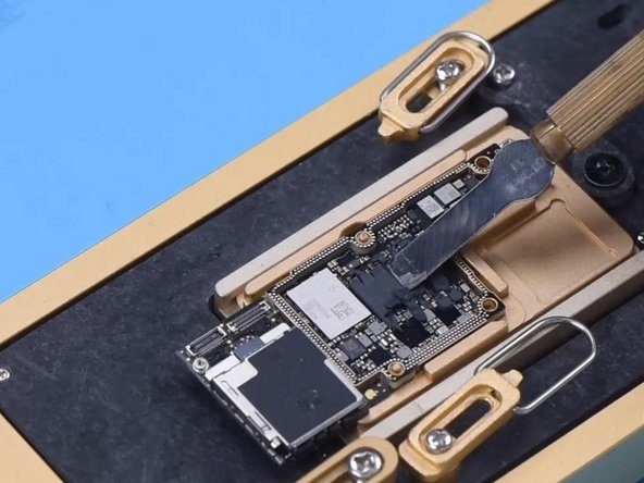
Step 1


- Gently peel off the foam covering the motherboard before you start heating.
- Heads up: if you're new to this, heating the motherboard with a hot air gun isn't the best idea since the heat might spread unevenly and cause warping. We recommend using a professional motherboard heating platform instead.
- To make removing the logic board easier later on, secure it by driving in a screw.
- Carefully slice through the tape using a Sculpture Knife.
Step 2


- The logic board and middle layer are gently bonded with low-temperature solder paste. For the best results, aim for a heating platform temperature between 155°C and 165°C.
- Once the platform reaches 165°C, carefully nudge the logic board with tweezers. If it feels loose, you've hit the sweet spot – the solder's melted!
Step 3


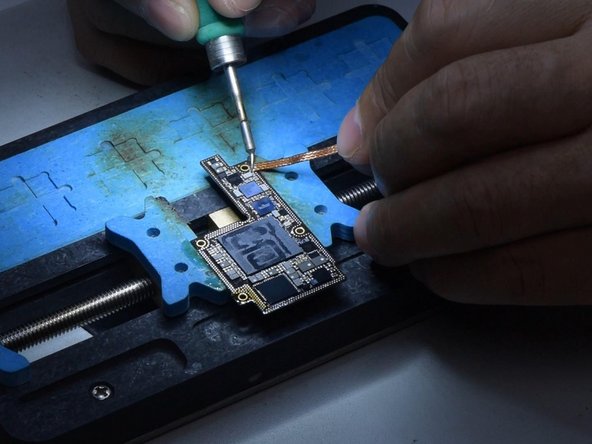
- Give that screw a gentle clamp to free the logic board, then slide out the signal board like a pro.
Step 4

- Carefully scrape off the thermal grease using a Sculpture Knife.
- Make sure to remove all the thermal grease—if any is left, it could touch the logic board and cause unwanted soldering when you put things back together.
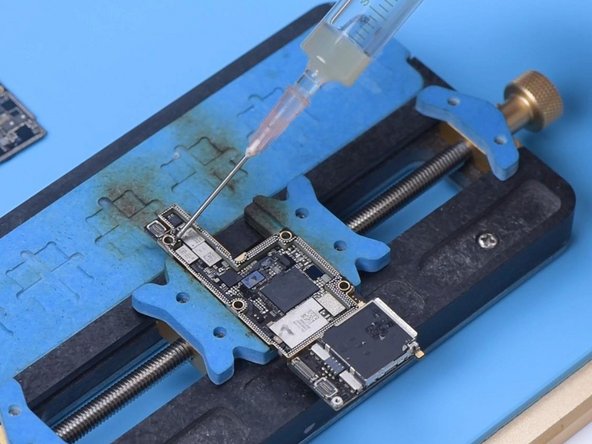
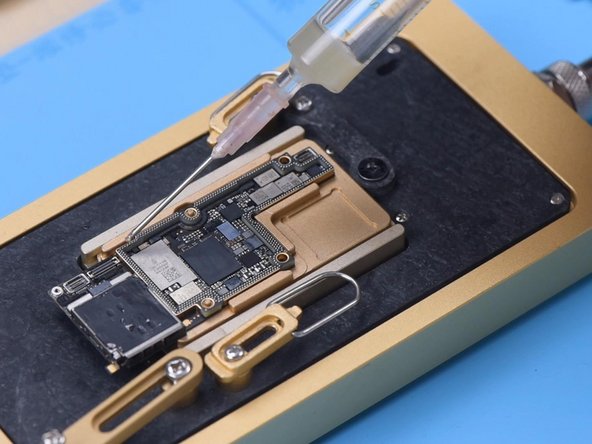
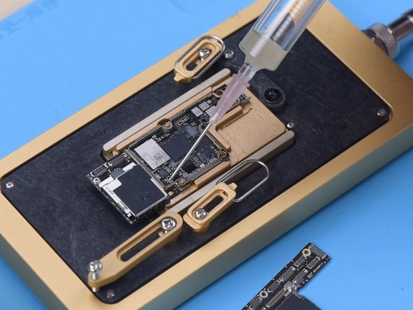
- Secure the signal board in the holder and apply a neat layer of Paste Flux all around.
Step 5

- First, grab your soldering iron, set it to 365°C, and carefully work on removing the tin from the bonding pad. A little heat goes a long way!
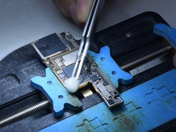
- Make sure you get all the tin off. Leftover solder can mess with your future soldering, so go for a clean slate!
- Time to clean up! Use some PCB cleaner to wipe down the bonding pad and make it sparkle.
- Now, clean up the logic board the same way. Just be careful not to mess with the components around the bonding pad. After cleaning, double-check the pad to ensure it's all neat and ready for the next step.
Step 6

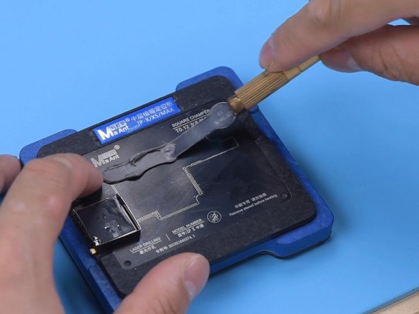
- Secure the signal board onto the Reballing Platform. Place the reballing stencil carefully to ensure it sits snugly against the signal board.
- Slide in a metal plate to keep that solder paste from sneaking into the motherboard gap.
- Spread a thin layer of low-temperature Solder Paste, then wipe away any extras using a lint-free wipe. Lift off the reballing stencil and double-check that the solder paste fully covers the signal board.
Step 7

- When applying solder paste, just a friendly reminder to keep an eye on the humidity levels! Too dry, and you'll find the paste sticking to the reballing stencil instead of the signal board, leading to an uneven application. Let's avoid those soldering mishaps together!
Step 8

- Pop that signal board onto a 165 °C Heating Platform and let it warm up until the solder balls are looking nice and round. Once you've got those shiny little spheres, turn off the heat.
- Once the signal board cools off, dab on a bit of Paste Flux—just a small amount will do the trick.
Step 9

- Place the logic board carefully with the signal board. Keep it on the 165°C heating platform for some time. Once the solder flux starts to spill and the logic board settles in, use tweezers to gently nudge it. This small, gentle adjustment helps the two layers fit together snugly. Just a light touch, no force needed!
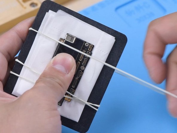
- Once the motherboard has cooled down, give it a good clean with PCB Cleaner. If the board looks a bit off after you've put it back together, don't panic! Simply place it on a flat surface and use a rubber band to hold it in place. Gently press both sides, but make sure you use soft paper underneath to avoid damaging any components. If you’re feeling unsure, feel free to schedule a repair for some extra help!
Step 10

- Next up, let’s look at another recombination method! You can use this if the middle bonding pad is in good shape and hasn’t been damaged.
- When the tin starts to melt, gently lift the logic board using tweezers, moving vertically. Around the signal board, you'll notice a thin metal pad (0.05 mm thick) at a slight distance. This pad helps maintain a tiny 0.05 mm gap between the logic board and the middle layer, which keeps solder balls from bridging while you're soldering.
- Only remove the thermal grease from the motherboard once the repair is complete. Keep the original tin on the bonding pad and add a touch of Paste Flux for smooth sailing.
- Finally, align the logic board with the signal board. When the temperature hits 165 °C and the tin melts, turn off the power. Press down on both ends of the logic board with tweezers until everything cools down. This will ensure the logic board and signal board fit together perfectly, with no bridging or spillover of solder balls.


