iPad 3G Logic Board Replacement
Duration: 45 minutes
Steps: 23 Steps
Ready to swap out your iPad 3G's logic board? Follow these steps and you'll have your device feeling smarter in no time. Grab your tools, stay patient, and let’s get your iPad back in action!
Step 1


Put on those safety glasses to keep your peepers safe, and watch out for that LCD screen – it’s more delicate than it looks!
This will help keep those pesky glass shards in check and maintain the strength of your display while you're prying and lifting it up.
- If your display glass is cracked, keep it from shattering further and avoid any ouch moments by taping over the glass before you start.
- Cover the iPad’s screen with overlapping strips of clear packing tape until the entire front is wrapped up snugly.
- Follow the rest of the steps as best you can. Just a heads up: once the glass is broken, it might keep cracking as you go, so you may need to carefully use a metal prying tool to lift the glass pieces out.
Step 2


The iPad in the photos might have a slightly different look than yours, but don't worry—the steps are the same!
- Slide a metal spudger right between the display assembly's edge and the rear panel assembly. You're doing great!
- Now, give that spudger a little twist away from you to pop those tabs loose along the top edge of the display. Keep it up!
Tools Used

Step 3


- Slide a second metal spudger between the top edge of the display assembly and the rear panel to keep those tabs from snapping back like a surprise party.
- Gently pry the display assembly away from the rear panel—think of it as coaxing a shy friend out of hiding.
Tools Used
Step 4


Take it slow when you're nearing the top edge of the iPad! There's a delicate ribbon cable hiding just beneath the surface, and it's super easy to accidentally damage it. Proceed with care, and you'll be all good!
- Keep gently working your way along the bottom and left sides of the iPad, prying the display assembly away from the rear panel. Take it slow and steady—your iPad appreciates the gentle touch!
Step 5

Be careful not to lift the display too much—there's a delicate antenna cable still connecting the two parts, and it's got barely any slack. A little goes a long way here!
- Gently lift the display assembly from the rear panel by its bottom edge, like you're peeling a banana. You've got this!
Step 6

- Grab the flat end of your trusty spudger and gently wiggle it under the antenna connector that's hanging out near the bottom of your iPad. Give it a little nudge to lift it up and away from its cozy spot on the communications board. You're doing great!
Step 7

- Alright, let's get to it! In the upcoming steps, we're going to carefully unplug the three cables that connect the display assembly to the logic board. These little guys are responsible for some important features like:
- Digitizer
- Ambient Light Sensor
- Display Data Cable
Step 8


Heads up: make sure you're lifting up the little locking flap, not the whole socket—your device will thank you!
- Use the edge of an iPod opening tool to gently lift the retaining flaps that keep the digitizer ribbon cables in place on the logic board. It’s like popping open a little secret compartment, but with precision.
- Carefully pull the digitizer ribbon cables straight out of their sockets. A steady hand here will make all the difference—no need for force, just a smooth, controlled move.
Step 9

- Grab your trusty iPod opening tool and gently pop the ambient light sensor connector out of its socket. A little upward pry and you're good to go!
Step 10

Gently tug the connector straight out, keeping it level with the surface of the logic board. You've got this!
- Gently flip up the metal latch using the black plastic pull tab to unlock the display data cable from the main board.
- Carefully slide the cable connector out of its socket.
Step 11

- Carefully detach the display assembly from the back panel assembly.
Step 12

- Gently use the edge of your iPod opening tool to pop up the last antenna connector from the communications board. Take it slow—no need to rush. You’ve got this!
Step 13


- Guide that control button cable along the top edge of the communications board—like you're laying down a groovy track.
- Gently lift the communications cable straight up to pop its connector out of the logic board socket. Smooth moves!
Step 14

- Unscrew the lone T5 Torx screw that's holding the communications board snugly against the rear case. You've got this!
Step 15


If needed, gently lift the right edge of the communications board to pop it free from the sticky adhesive pad holding it to the rear case.
- Gently pull the communications board out of its socket on the logic board, like you're unplugging a tiny secret agent.
Step 16

Make sure to lift the little flap, not the socket itself—treat it gently like it’s a tiny secret!
- Gently lift the rubber EMI shield off the GPS antenna socket, like you're peeling a banana—easy does it!
- Grab your trusty iPod opening tool and use the edge to nudge up the GPS ribbon cable retaining flap that's holding the GPS cable to the logic board. It's like giving it a little high-five!
Step 17

- Gently wiggle and slide the GPS antenna ribbon cable out of its socket. Take it slow, and it should pop right out!
Step 18

Heads up! Make sure you're lifting the retaining flap—not the socket itself—when prying. That little flap is the star of the show!
Gently slide the cable over to the left side of the iPad. Just a little nudge, and you're on your way!
- Grab your trusty iPod opening tool and gently flip up the little retaining flap on the headphone jack/mic socket—think of it as opening a tiny gate for your cable.
- Now, slide that headphone jack/microphone ribbon cable out of its socket with care. Easy does it!
Step 19

That connector might be hiding under some black tape. Grab your tweezers, peel it away, and then you’re good to go!
- Gently use an iPod opening tool to lift the SIM board connector off the logic board socket. Take it slow and steady, you’ve got this!
Step 20

Gently lift from under the wires, taking care not to tug too hard. A little patience goes a long way here!
- Gently fold the SIM cable down toward the bottom of the iPad to reveal the speaker connector.
- Carefully use the edge of an iPod opening tool to lift the speaker connector out of its socket on the logic board.
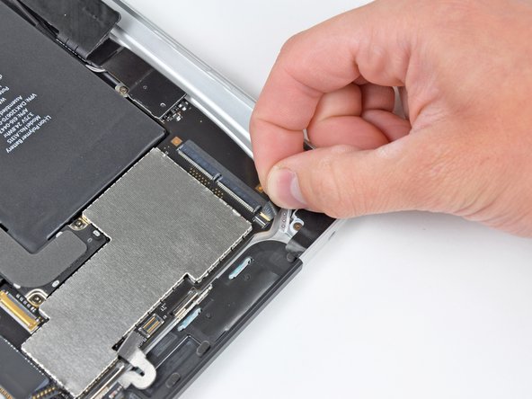
Step 21

- Ready for some unscrewing action? Let’s free the logic board from the rear panel by removing these screws:
- Two 4.56 mm T5 Torx screws—grab your trusty driver!
- Two 3.76 mm T5 Torx screws—don’t mix them up, they’re a bit shorter!
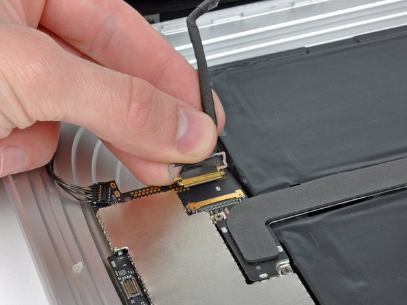
Step 22

- Gently slide the edge of an iPod opening tool under the dock cable connector and lift it straight up off the logic board with care.
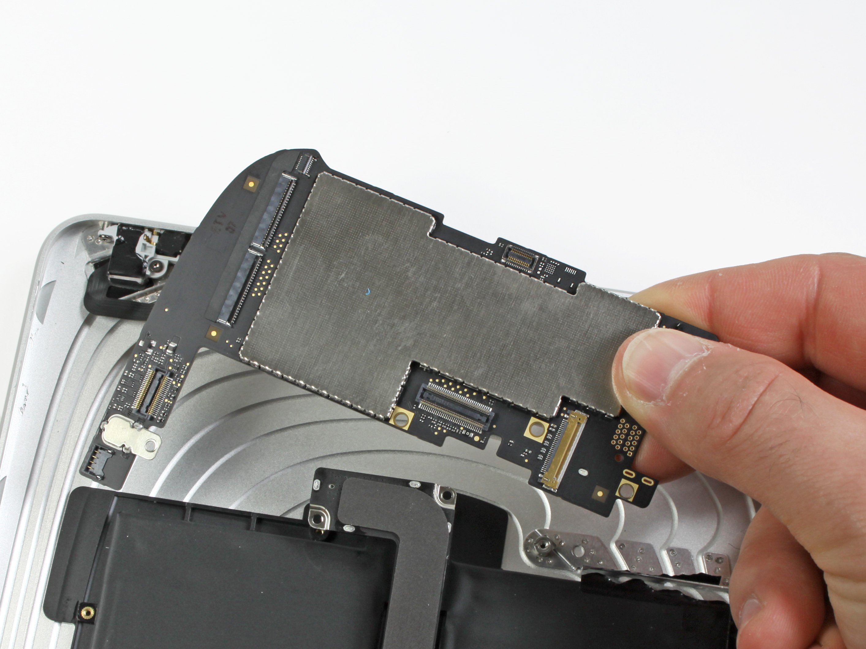
Step 23

- Gently wiggle and lift the logic board out from the cozy confines of the rear panel assembly. You've got this!


