Insignia Flex 10.1 Microphone Replacement
Duration: 45 minutes
Steps: 10 Steps
The microphone on your Insignia Flex 10.1 is your trusty sidekick for audio and video calls, capturing those memorable moments, or even following your voice commands like a champ. Ready to give that mic a makeover? Dive into this guide to swap it out and keep the conversations flowing!
Step 1

Just a heads-up, when you remove the rear panel from the back of the Flex 10.1, there’s a chance it could get damaged. Take it easy and be careful!
Step 2


The rear panel is held in place by 26 little clips that cling to the front case like a kid to their favorite toy. These clips snugly secure themselves to tiny tabs crafted into the front case.
To release those tabs, give them a gentle nudge toward the center of the device. When you’re using your trusty plastic opening tool to pop off the rear panel, make sure to focus on those clip locations. You’ve got this!
– Picture this: the 9 clips highlighted in red are chilling right next to the volume buttons, ready for action!
– To pop off the back cover, just grab a plastic opening tool and slide it along the edge of your device to free those clips. Easy peasy!
Step 3

Getting inside the Flex 10.1 can be a bit of a challenge, but don’t worry if it takes a few tries to crack it open – you’ve got this!
– Slide the plastic opening tool into the little gap between the front and back of your Flex 10.1.
– Gently work the tool to widen the gap by pressing and wiggling it near each clip holding the back case, nudging those clips toward the center until they pop free.
– Keep going with this method to release all the clips around your Flex 10.1.
Step 4

– Once you’ve made sure all the clips are free, gently pry apart the two halves of the Flex 10.1.
– Congratulations! The rear panel is now liberated from the Flex 10.1.
Step 5

– Now that you’ve popped off the rear panel, the back side of your Flex 10.1 should be looking all sorts of ready for action!
Step 6

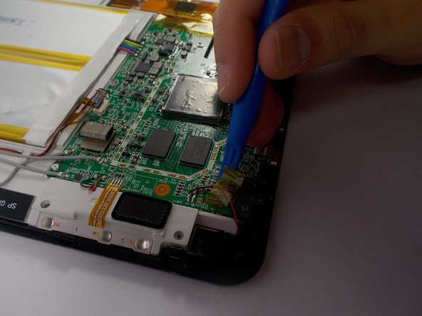
Handle the motherboard with care, it’s a delicate area of your device. Make sure not to scratch it while you’re peeling off that tape!
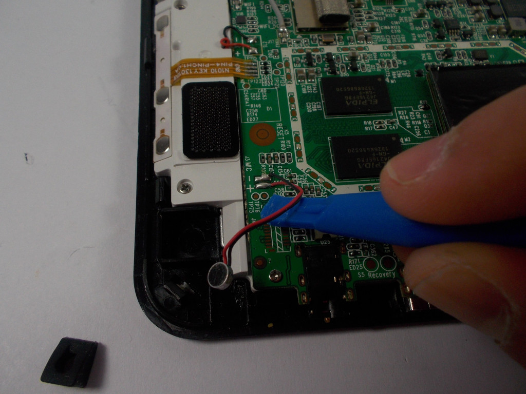
– Grab your trusty plastic opening tool or just your fingers, and gently peel away the tape that’s keeping those black and red wires in check. You’ve got this!
Step 7

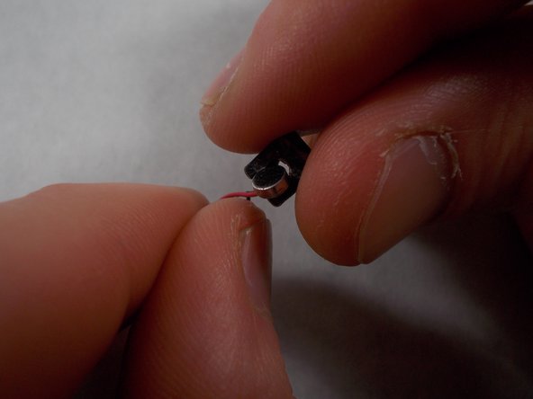

The microphone is snugly wrapped in a sleek black silicone cover, keeping it safe and sound.
– Carefully take off the microphone cover by gripping the wire and gently pulling it away. You’ve got this!
Step 8

Electronic components can be a bit sensitive to heat, so it’s important to avoid transferring too much from the soldering iron to the motherboard. A smart trick is to gently pull the wires with a steady, light tension while the soldering iron does its magic. This way, you’ll keep things cool and under control!
Get ready to break out that soldering iron for the next few steps!
If you’re just getting the hang of soldering, it might be a good idea to check out a soldering technique guide. It’s all about mastering those connections!
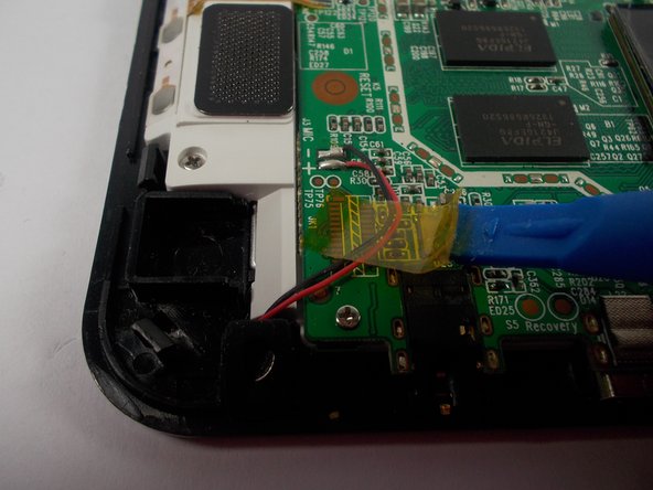
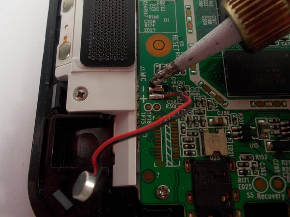
You’ll notice that the microphone is linked to the motherboard with a snazzy red and black wire.
– Start by warming up those two solder joints on the motherboard, tackling one at a time.
– As soon as the solder gets all melty and the wire pops free, quickly lift the soldering tip off the connection to keep everything safe and sound!
Tools Used

Step 9

– Congratulations! You’ve successfully liberated the microphone from the motherboard.
Step 10

The motherboard clearly shows the positive and negative signs, and the picture helps too, so you won’t miss a thing!
– Time to get that new microphone cozy with the motherboard! Just solder it onto the same joints where the old one was hanging out.
– When you’re soldering, think of it as a quick dance move: briefly touch the soldering iron to the connection, sprinkle in some solder (like confetti!), and swiftly pull both the solder and the iron away. Watch the magic as the solder flows around the wire and motherboard, creating a solid bond.
– Don’t forget, the black wire is the cool kid that belongs on the negative joint.
– And the red wire? That’s the superstar that needs to be on the positive joint.