Asus Transformer Pad TF103C Screen Replacement
Duration: 45 minutes
Steps: 27 Steps
Is your Asus Transformer Pad (TF103C) display acting a bit moody? Is the LCD screen giving you the silent treatment with a black or glitchy display? Don’t worry! We’ve got your back with a step-by-step guide to help you swap out that LCD screen like a pro. Just a heads up, this process has over 25 steps—so it’s a bit of a journey! You’ll need to remove several small electronic parts and chips to get to the LCD display, but hey, you’ve got this! And remember, if you come across a punctured battery, handle it with care to avoid any fiery surprises. If you need help, you can always schedule a repair.
Step 1

Before you dive in, double-check that the SD card slot is completely empty—no surprises, no mysteries, just a smooth repair ahead!
If you don’t have an opening tool handy, a slim screwdriver can do the trick—just go easy and keep it smooth!
– First, make sure your tablet is completely powered down – we don’t want any unexpected start-ups getting in the way.
– Next, find a thin crack on the side of your tablet and carefully insert the plastic opening tool – this is where the magic begins.
– Now, gently pry the tool upwards to carefully loosen the Transformer pad – take your time, you got this.
Step 2

– Gently slide the tool into the gap around all four sides while pulling it upward. You’ve got this!
Step 3

– Gently pop off the back cover once it’s feeling a bit loose and put it to the side like a pro.
– Twist that tablet around until it lines up just like the picture. You’ve got this!
Step 4

– Gently unplug the battery cable from the motherboard by gripping the wires near the black piece and carefully pulling it out of the housing. Trust me, you’ve got this!
Step 5


Swap out the old battery for a fresh +3.7V=19Wh Li-polymer Battery Pack C11P1328.
Heads up: there might be some sneaky tape on the battery, so you could hear a little Velcro-like sound as you carefully pry it out.
– Gently ease the battery out of the tablet using the opening tool—take your time, it’s all about finesse!
Step 6
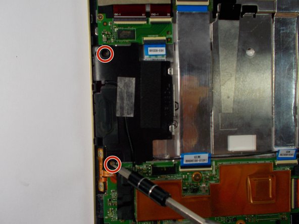

– Grab your trusty +J000 screwdriver and remove two screws from each speaker—precision is key!
– Keep those screws together like best friends. A little organization goes a long way, so label if needed!
Step 7

Be careful not to tug on the wire too hard, or it might just decide to take a permanent vacation!
If the wire happens to snap off, no worries! You can totally solder it back on like a pro.
– Gently unplug the wire from the top of the left speaker—like you’re disconnecting a friend from a long, awkward group chat.
Step 8

– Peel off that yellow tape like a pro and disconnect the wire linking the speakers to the soundboard. You’ve got this!
Step 9


– Take out the two speakers from the device’s frame. This is a great opportunity to get a closer look at the inner workings of your device and see how everything fits together.
Step 10

– Grab your trusty +J000 screwdriver and remove the screw shown in the picture. After that, gently peel off the plastic cover labeled ‘M2’.
– Quick heads up: Removing the screw will break the seal sticker, so keep that in mind!
Step 11

Gently pop open the ribbon cable connector by lifting the white part up and swinging it to the left. Easy does it—you’re doing great!
– Peel off the black tape from the ribbon cable and gently detach the cable from the soundboard. You’re doing great!
Step 12

– Carefully take out the screws from the soundboard using your trusty +J000 screwdriver. You’ve got this!
Step 13

– Take out the soundboard with care.
Step 14

– Peel away the black tape from the motherboard with care. Disconnect the ribbon cable linked to the volume and power buttons—you got this!
Step 15

– Using the trusty +J000 screwdriver, take out those three motherboard screws—like a pro!
Step 16

– Let’s get started by unplugging all three ribbon cables from the motherboard. This is a crucial step, so make sure to carefully disconnect them.
Step 17

– Gently detach the camera’s ribbon cable from the underside of the motherboard—think of it like unplugging a tiny, delicate lifeline. Once free, go ahead and lift out the motherboard.
Step 18

– Grab your trusty +J000 screwdriver and unscrew the two keyboard connector screws. It’s a small step, but it’ll make all the difference. Easy does it!
Step 19

– Time to get that charging port chip ready for action – start by peeling off the tape that’s covering it.
Step 20

– Disconnect the two ribbon cables from the charging port chip with care.
Step 21

– Unscrew those two little charging port screws using your trusty +J000 screwdriver. You’ve got this!
Step 22


– Time to get your hands dirty – carefully remove the charging port chip and the keyboard connector chip.
Step 23

– Let’s get started by removing all eight screws from the metal frame using your trusty +J000 screwdriver. Take your time and make sure they’re all out before moving on to the next step.
Step 24

Keep that left side of the tape firmly in place—no peeling allowed!
– Gently peel away the shiny metallic tape from the left side of the frame—like you’re unwrapping a little present, but cooler.
Step 25

Keep an eye on those power and volume ribbon cables tucked away in the lower left corner. They’re a little shy, but we don’t want them to get lost during the repair!
– Gently pry the frame away from the device, taking care not to snag it on any wires – we don’t want any accidental tangles!
Step 26

Take it slow and steady—keep that glass screen cover in one piece!
You might hear a few cracking sounds as you break the adhesive, but don’t worry—it’s totally normal!
– Grab that trusty plastic opening tool and gently pop the display screen loose from the front panel—it’s like opening a stubborn jar, but way cooler!
– For a smoother move, whip out some opening picks and slide them around the screen tape like you’re choreographing a tiny dance. Heads-up: that tape might need a fresh replacement. Stay awesome!
Step 27

– Time to swap out that broken display screen! Grab your tools and get ready to bring your device back to life with a shiny, new screen.