Helium FreedomFi 5G Gateway Miner Teardown
Duration: 45 minutes
Steps: 5 Steps
Taking apart the FreedomFi 5G Gateway Miner uncovers a straightforward setup: a basic Celeron J1900 Bay Trail embedded board with 4GB of RAM, a 64GB mPCIe M-SATA SSD, and a mPCIe RAK Wireless LoRa card. With a little patience, you’ll see all these components laid out clearly. If you need a hand during reassembly or encounter something tricky, you can always schedule a repair.
Step 1
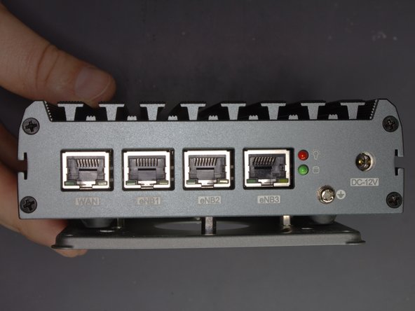


– Let’s take a quick tour of the device’s ports and indicators before diving in. On the front, you’ll find the Power Button, two USB-A ports, a Console Port (that’s RS-232 rollover RJ-45 style), and an Antenna Connector (female RP-SMA). Flip it around to the back, where the WAN port (RJ-45), eNB1-3 ports (RJ-45), power indicator light (red), HDD activity light (green), grounding stud, and the DC Power In (12V, 3.3A, center positive) are waiting. The bottom part of the device is marked with the model number: FFG-HL-4-64, along with the Chip FCC ID: 2AF6B-RAK5146 and Chip ID: 25908-RAK5146. This overview helps you get familiar before starting your repair journey. If you need help along the way, you can always schedule a repair.
Step 2
– Up front: Take out 4 Phillips screws and loosen the antenna’s retaining nut.
– On the back: Remove 4 more Phillips screws.
– Down below: Another 4 Phillips screws to go.
– All these screws are identical, so no need to worry about mixing them up!
Step 3
– Check out the HDMI port chilling on the front—this is where you’ll see your console’s output.
– On the back, you’ll spot a 12V power block ready for bare-wire action.
– Installed modules roll call:
– RAK LoRa Concentrator (RAK5146) is in the house.
– Foresee 64GB mPCIe SSD brings the storage muscle.
– 4GB DDR3 RAM keeps things speedy.
Step 4
– To start, locate the RAM module and find the small levers on each side of the green chip—they’re what hold the RAM in place. Gently push them outward to release the module. Next, find the LoRa Concentrator—it’s secured with a single screw in the top right corner, marked yellow—unscrew it carefully. Then, look for the SSD, situated at the top left, held down by one orange screw—remove that with a suitable screwdriver. Finally, identify the main board, which is secured with four Phillips screws at each corner, marked in red—unscrew each one to free the board. If you need help, you can always schedule a repair.
Step 5
– Board: Piesia BT19NE4L ( http://en.piesia.com/prod_view.aspx?Type… )
– Processor: Intel Celeron J1900 ( https://ark.intel.com/content/www/us/en/… )
– Connectors & Diagram (Orange): You’ve got your HDD light, Power light, Reset switch, Power switch, and Speaker all ready to rock!
– SIM slot (Red): Don’t forget about your SIM slot, it’s a vital part of the crew!
– GPIO (Yellow): And here’s the GPIO, adding some extra flavor to your setup!