Nintendo 3DS XL 2015 Top Display Casing Replacement
Duration: 45 minutes
Steps: 17 Steps
Get ready to crack open and swap out that top display casing like a pro! This step-by-step guide from Salvation Repair will walk you through the process with ease. Follow along and you’ll be done in no time.
Step 1

Make sure your device is completely powered down before diving in—nobody likes a surprise zap or a device on the fritz!
– Flip your 3DS upside down like you’re showing off its moves. Make sure to remove the game card, headphones, charging cable, stylus, or any other gear that’s hanging out with the device.
Step 2

The screws are chillin’ there thanks to those clever captive washers, so no need to fully remove them—just loosen and let them stay in place.
– Grab your trusty JIS #0 screwdriver and carefully back out the two black screws on the rear—easy does it!
Step 3

– Now that the screws are loose, gently pop off the back cover. Easy does it!
Step 4

– The battery hangs out on the left side of the 3DS. To pop it out, find the little gap up at the top-middle and gently lift it up with a non-metal, pointy tool. Easy does it!
Step 5

– Grab your JIS #00 screwdriver and remove those six 6mm screws circling the edges of the secondary cover like a pro.
Step 6


– Time to get started! Use your trusty tweezers to carefully pry out the rubber bumpers at the top of your 3DS. This will expose two more 6mm screws – remove them using a JIS #000 screwdriver. You’re making great progress!
Tools Used

Step 7


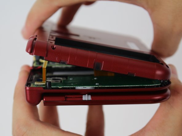
Be careful not to completely remove the cover just yet! There’s still a fragile ribbon cable connected to the motherboard, and we don’t want any damage to occur.
– To detach the cover, gently lift it up and away from the hinges (make sure to clear the headphone port), then swing it towards the hinges to reveal the circuit boards.
Step 8

– Grab your trusty tweezers and carefully lift off the two plugs securing the L/R/ZL/ZR button ribbons to the motherboard. Once that’s done, the back cover is free to come off—set it aside and give yourself a pat on the back for a job well done!
Tools Used
Step 9

Be careful when connecting the cable to the ZIF connector – it’s easy to get it wrong! The cable folds in from the left, but the locking flap opens from the right. Make sure you’re not trying to pull it up from the same side as the cable, or you might end up damaging the connector. Take your time and get it right!
Unscrewing and taking out the Circle Pad first might just make your life a whole lot easier before tackling that cable! And when it’s time to put everything back together, feel free to connect the cable first before sliding the unit back into place. You’ve got this!
– Grab your trusty tweezers and gently lift the tiny, hinged locking flap to unlock the ZIF connector that’s holding the Circle Pad ribbon in place. You’re almost there!
– Now, smoothly slide that ribbon out of the ZIF connector like a pro. Easy peasy!
Tools Used
Step 10

– Grab your trusty JIS #000 screwdriver and let’s get to work! Carefully remove those two 8 mm screws that are holding the circle pad in place. You’ve got this!
Step 11

– Gently lift the circle pad casing upward to pop it off. It might feel a bit snug, but no need to hulk out—just a steady hand will do the trick!
Step 12

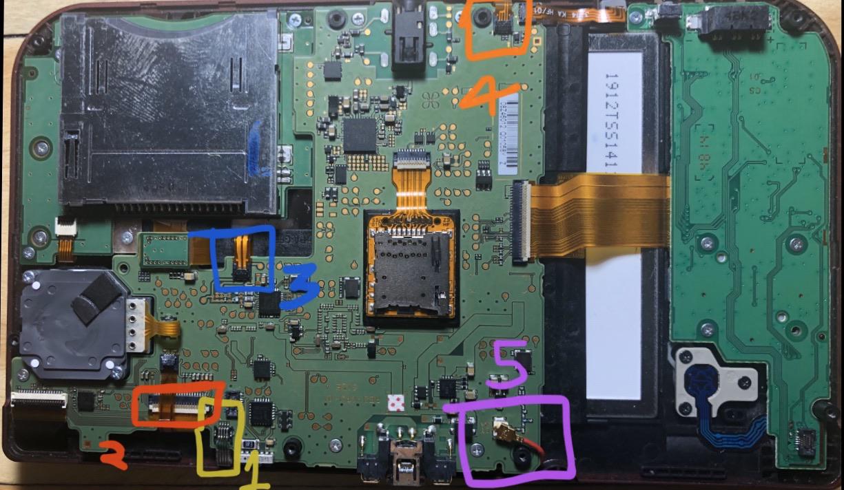
Take it easy and keep cool—don’t tug on that red cable, or it might ruin your day!
– Spot the gold terminal plug hooked up with a red cable chilling at the top-left corner of the motherboard. Gently grab it with your fingers and give it a straight upward pull to pop it off—no twists, no turns, just up and out!
– Grab your trusty tweezers and carefully disconnect the single ribbon connector. Take your time—precision is key!
Tools Used
Step 13


Heads up! These ZIF connectors stay put thanks to friction—no fancy locks involved. But be careful—lifting the flaps on these connectors will snap them!
Oops, correction time! This connector was thought to be lock-free, but on most systems, it does have a sneaky little lock. If you try to yank or shove the cable without unlocking it first, you’ll risk damaging it, which means replacing the Touch Screen’s digitizer. Good news, though—the LCD uses different ZIF connectors, so you’re in the clear there.
Now, if your system’s connector really doesn’t have a lock after all, resist the urge to tug at the flap! It should come out smoothly. If it’s stuck, it’s likely just secured by friction. In that case, give the cable a gentle pull to slide it out of the connector. Patience pays off here!
While the SD card reader is shown as removed in this image, it’s totally optional for popping out the motherboard.
– Grab your trusty tweezers and gently lift the four marked ribbons from the ZIF connectors on the motherboard sides. Easy does it!
– Three of the ribbon connectors have little plastic flaps to hold the ribbon in place. Use those tweezers to flip them up before you start removing the ribbon. Don’t worry, they won’t bite.
– The last ribbon connector might have a plastic flap too, but it’s not quite the same as the others. Think of it more like the one used for the Circle Pad. Gently flip the flap on the side opposite the ribbon cable to safely remove it.
– When putting everything back together, don’t forget to push those ZIF clamps back down. It’s a small step, but it’s key to finishing the job!
Tools Used
Step 14

– Let’s get started! Remove six 4mm screws along the edges of the motherboard using a trusty JIS #000 screwdriver. Easy peasy!
Step 15


Pay attention to how those ribbons are sliding into their connectors—they each have their own style, and it’s not one-size-fits-all!
– Gently swing the motherboard 90 degrees toward the hinges to uncover two sneaky ZIF connectors hiding on the underside.
– Both connectors have little latches you’ll need to flip up. The left one’s a longer, black latch, and the right one’s a shorter, white latch. Pop those flaps up, slide the ribbons out, and voilà, the motherboard is ready to be removed!
Step 16


– Grab your trusty 1.5 flat head and pop off those four red rubber stickers hiding inside the casing—it’s like a scavenger hunt, but for stickers!
– Next up, whip out your PH00 screwdriver and loosen those screws with confidence. You’re practically a pro already!
– Underneath the rubber stickers lies a silver sticky layer. Peel it off with finesse—you’re uncovering hidden treasures!
Step 17


Heads up! We’ve recently updated this step to keep you safe. The old method was a bit sketchy, and we don’t want you to risk damaging your device. So, please avoid using a spudger to slide around the edges – it’s a surefire way to snap those tabs off!
– To put your device back together, just follow the steps in reverse—it’s like hitting rewind on your favorite playlist.
– If you need help, you can always schedule a repair.
Success!