Dell XPS 13 Disassembly
Duration: 45 minutes
Steps: 7 Steps
Step 1
– This one’s on us!
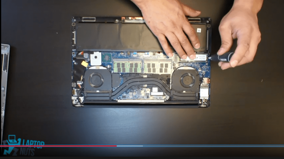
– Equipped with an Intel Core i7-8550U QUAD CORE processor and 8 GB of RAM (with the option to upgrade to 16 GB) along with a lightning-fast SSD, all packed into a sleek chassis that’s smaller than ever.
– Quick note: those original Toshiba drives might not perform at their best. Consider switching to another slip for 500MB read/write speeds!
– Wow, this is wild! But how much heat does it actually generate?
– With a TDP of 15W, there’s definitely some flexibility. Especially since Dell decided to include a better fan.
Step 2
Even though some Philips screw threads are on the larger side, not every one of them can be tackled with a PH 1 screwdriver. A PH 0 can also come in handy for those smaller screws, and as long as it fits snugly, it won’t strip the screw.
Fortunately, these are the only 8 T5 screws you’ll need to deal with. Once you’ve conquered them, you can set that aside and grab your trusty PH 0.
– Alright, under that shiny XPS sticker cover, there’s a Philips screw waiting to be discovered. Let’s uncover it like a treasure!
– Got it? Perfect. Time to grab your trusty PH 0 screwdriver and get to work. It’s small but mighty!
– Whoa, these T5 screws mean business! They’re putting up a fight, but don’t worry—stay patient and steady. If your bit feels a little worn, just take it easy and keep at it!
Step 3
Unlike the previous XPS chassis, this one comes with a bit of a chaotic twist—but hey, nothing we can’t handle with a little patience and some steady hands!
– Alright, get ready to face some seriously stubborn clips. These things are holding on like their life depends on it.
– Turns out, all these clips push outward—no hinges here to make life easier. So, yeah, you’ll need a little muscle for this part.
– Here’s the trick: start on the side with the card reader. That area’s a bit more forgiving. Just take your time and use steady force. The chassis and back cover are tough, so don’t worry about breaking them.
– Oh, and a friendly reminder—ditch the metal tools for this. You don’t want to scratch up those sleek aluminum edges. Trust me, you’ll thank yourself later!
Step 4
– Alright, let’s get rolling! First things first—what’s next on the list?
– To keep things groovy, let’s start by dealing with the display—this makes life a lot easier.
– Here’s the plan: pop off the display connector hiding under the motherboard bracket, and don’t forget the antenna chilling under the WLAN bracket. Easy peasy!
– Oh, and you’ll have to handle that funky ‘screw-in-tape’ situation… Yep, we know—kind of a buzzkill!
– Now about the camera? It might just be the one tagged M/B. Doesn’t that sound official?
– Wait, why M/B? Good question—let’s just roll with it, shall we?
Step 5
– Next, let’s get that battery out of there!
– You’ll need some 2*M2 screws, or at least that’s what the labels say…
– Grab your trusty PH 1 screwdriver.
– Now, sometimes those screws can be a bit stubborn and seem overly tight. But don’t worry, if the case screws on your laptop start to scatter like confetti, it’s a different story altogether!
– As for the battery and speaker screws, it’s not a big deal to loosen them just a tad.
Step 6
– Alright, let’s dive into what we’ve got here!
– We’re looking at the motherboard, and it seems there’s an I2C touchpad, a keyboard, and a light—all hooked up to an interconnect board loaded with a few chips.
– You might ask why all this is on an interconnect board, but hey, the motherboard already has its hands full.
– Compared to the 2012 model, this one is stepping up its game with USB-C, a card reader, and some mystery ports.
– Oh, and here’s a fun fact: this chassis gets double duty in precision mobile workstations—explains all those unsoldered ports and even the SATA settings in BIOS.
Step 7
– Put your device back together by retracing your steps—it’s like an epic puzzle coming full circle!
– If you need help, you can always schedule a repair.
Success!
