Microsoft Surface Pro 5 Front-Facing Camera Replacement
Duration: 45 minutes
Steps: 35 Steps
Be careful not to break the display panel during this step – it’s super fragile and might not survive some rough handling!
Ready to give your Surface Pro 5 a front-facing camera makeover? This repair will help you swap out the infrared face-detection camera and the front-facing main camera. Plus, if you’re feeling ambitious, applying fresh thermal paste on the CPU during reassembly could boost your Surface’s performance. You’ll just need new thermal paste and high-concentration isopropyl alcohol or a specialized thermal paste cleaner. Bear in mind, the display panel is delicate—like, really delicate—so take your time, use plenty of heat, and show some extra TLC during the prying process. You got this!
Step 1

Totally shut down your Surface before diving into the teardown adventure.
Need extra warmth? Grab a hair dryer, heat gun, or hot plate—but go easy on the heat! The screen and internal battery aren’t fans of being toasted.
You might find yourself needing to give the iOpener a little extra love by reheating and reapplying it a few times to get that Surface nice and toasty. Remember to check the iOpener instructions to keep things from getting too hot to handle!
– Got a cracked screen? Keep those shards in check and protect yourself while you’re at it! Slap some overlapping strips of clear packing tape over the glass until every bit is covered. Safety first—pop on a pair of safety glasses to shield your eyes from rogue fragments.
– Warm up an iOpener and give the right edge of the Surface’s screen a cozy two-minute hug. The heat will help loosen things up for the next steps.
Tools Used

Step 2


– Get familiar with the layout of the screen adhesive—it’s like a map for smooth sailing ahead.
– This zone here? It’s all adhesive, so you’re safe to cut without worries!
– Watch out near the edges! The display board and flex cables are hanging out close by. Slice gently and don’t go too deep under the display.
– Heads up for fragile antenna cables under this screen section! Stick to the guide and keep steady hands to avoid harm. Oh, and heads up—it’s also where the adhesive gets extra chunky!
Step 3


Be careful not to insert the opening pick too far into the screen – stop at the black bezel to avoid damaging the LCD. We want your repair to go smoothly!
– Grab an opening pick and slide it into the speaker opening on the screen, then run it gently under the glass. Keep it chill—don’t push the pick into the speaker grille, as it’s super delicate and can tear easily.
Step 4


– Time to get this repair started! Rotate the pick towards the bottom of the Surface, sliding it under the lower edge of the speaker cutout with ease.
Step 5


If you hit a roadblock and the pick doesn’t want to budge, don’t force it! Stop and give the section a little more heat. Too much pressure can lead to a cracked screen, and we want to avoid that. Take your time and let the heat do its magic.
– Glide your pick along the right edge of the Surface to slice through that stubborn screen adhesive—you’re almost a pro already!
– Keep that pick snugly parked in the right edge. It’ll act as a trusty wedge to keep the adhesive from sticking back together.
Step 6

Feeling the heat? A hair dryer, heat gun, or hot plate can kick things up a notch, but play it cool—overheating the Surface could make your screen and battery go on strike!
Keep your cool, but warm up the Surface! You might have to reheat and reapply the iOpener a few times to get it just right. Stick to the iOpener instructions so nothing gets too hot to handle.
– Time to get this repair started! Reheat the iOpener and apply it to the bottom edge of the Surface’s screen for two minutes. This will help loosen things up and make the next steps a breeze.
Tools Used
Step 7


Keep the opening pick shallow—don’t go deeper than the edge of the black bezel around the screen. A little restraint here keeps your LCD safe and sound!
– Grab a new opening pick and pop it into the bottom right corner, then glide it smoothly around to the bottom edge.
– Run that pick along the bottom edge of the Surface like a pro to slice through the screen adhesive.
– Leave this pick chillin’ in the bottom edge to keep the adhesive from sticking back together.
Step 8

You can use a hair dryer, heat gun, or hot plate for some extra warmth, but watch out—too much heat can be a real bummer for your Surface. The screen and internal battery are sensitive to overheating, so keep it cool and steady!
Keep your cool, but warm up the Surface! You might have to reheat and reapply the iOpener a few times to get it just right. Stick to the iOpener instructions so nothing gets too hot to handle.
– Warm up that iOpener again, then give the left side of your Surface’s screen a cozy two-minute heat treatment. You got this!
Tools Used
Step 9


Be super careful when slicing under the bottom 2.5 inches (65 mm) of the left edge. Keep that opening pick shallow—don’t go beyond 1/8 inches (3 mm)—because the display cables are chilling nearby and could get wrecked. Once you’re clear of the display cable zone, resist the urge to push the pick any deeper past the bezel.
– Pop in a fresh opening pick at the bottom left corner and glide it around the corner like a pro heading for the left edge.
– Work that pick along the left edge of the Surface to slice through the stubborn screen adhesive.
– Let this pick chill in the left edge to keep the adhesive from sticking back together.
Step 10

Feeling the heat? A hair dryer, heat gun, or hot plate can kick things up a notch, but play it cool—overheating the Surface could make your screen and battery go on strike!
The adhesive is super thick along this edge, so you’ll probably need to reheat and reuse the iOpener a few times to get the Surface nice and toasty. Stick to the iOpener guidelines to avoid overheating—patience is key, and you’ve got this!
– Time to get this repair started! Reheat the iOpener and apply it to the top edge of the Surface’s screen for two minutes. This will help loosen things up and make the repair process smoother.
Tools Used
Step 11


Now it’s time to tackle the top edge of the case. The next 6 inches (15 cm) are home to the left and right antennas, which are snugly sandwiched between the case and the screen bezel. Let’s get through these next steps with care – we don’t want any accidental antenna damage!
– Swing that opening pick around the left corner and glide it smoothly along the top edge of the Surface. Hold up when you’re 2.75 inches (70 mm) from the left edge—you’re cruising!
Step 12


Keep that pick cruising along parallel to the screen the entire time so it doesn’t snag the antennas. And hey, no need to jam it against the case—just let it glide!
– Slip the tip of a pick under the display where you left off cutting—don’t go deeper than the edge of the bezel, okay?
– Gently roll the pick to the right, pressing its long edge into the adhesive under the bezel. As you roll, slice through the adhesive—nice and steady. Oh, and don’t drag the pick along the Surface’s edge!
– Keep up this smooth move: insert the pick where you just cut, roll it to the right, and work your way along the top edge of the Surface. Stop when you’re 2.5 inches (64 mm) from the right edge. You got this!
Step 13


– After snipping the adhesive over the antennas (a handy 8.5 inches, or 22 cm, away from the left side), glide your pick smoothly along the top edge, rounding the top right corner like a pro to cut through the leftover sticky stuff.
Step 14


Hold up! The screen’s still hanging on—it’s connected to the motherboard by two cables, so don’t pull it off just yet.
– Time to carefully pry the screen assembly away from the Surface case. Take your time and don’t force it – if you hit any snags, double-check that all the adhesive is separated before proceeding.
– Grab an opening pick and use it to gently cut through any remaining adhesive that’s still holding things together.
– Keep an eye out – the flash lens might fall out of its spot in the Surface case. Make sure to set it aside safely and remember to put it back where it belongs during reassembly.
Step 15


– Gently lift the top of the screen assembly away from the case, sliding the bottom of the screen closer to the motherboard connectors. Easy does it—don’t rush this step!
– Carefully set the screen back onto the case with the connectors facing up. Make sure to treat those display cables with love and avoid creasing them. You’ll thank yourself later!
Step 16


Be gentle with the shield—it’ll need to make a comeback when you’re putting everything back together!
– Grab your trusty opening pick and gently shimmy it under one edge of the EMI shield hugging the display board. No need to rush, take your time!
– Work your way around the shield, repeating this smooth move at different points until the shield pops off like a charm.
Step 17

– Gently lift off the EMI shield from the display board and set it aside—you’re doing great, keep going!
Step 18


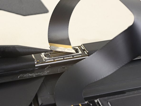
– Grab the flat end of a spudger and pop that display interconnect cable straight up and out of its socket on the board—easy does it!
Tools Used

Step 19


Keep the shield in good shape—you’re gonna pop it back on during reassembly, so no wild bends, okay?
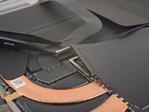
– Carefully insert one point of a pair of pointed tweezers into a gap in the edge of the EMI shield covering the digitizer connector – it’s time to set it free!
– Use those trusty tweezers to gently pry the EMI shield away from the display. Be patient and work your way around, taking care not to bend it.
– Repeat this process at different points around the shield until it’s completely free. Once you’ve managed that, you can remove the shield – nice job! If you’re feeling stuck, don’t worry, just take a deep breath and remember, you’re doing great!
Tools Used

Step 20

– Peel away the remaining shield from the digitizer connector like a pro and take it off completely.
Step 21

– Grab the tip of your spudger and gently lift the digitizer connector straight up, freeing it from its cozy spot in the socket on the screen.
Tools Used
Step 22

– Lift off the screen assembly from the Surface—nice and steady does it!
– When putting it all back together, stop here to refresh the screen adhesive by following this guide. It’ll look as good as new!
Step 23


– Gently grab a spudger and pop the microphone connector straight up and out of its socket on the motherboard—smooth and steady does it!
Tools Used
Step 24

– Grab your trusty T5 Torx driver and take on the four screws holding the antenna support in place:
– Three screws measuring 4.5 mm each
– One screw that’s 6 mm long
Step 25


– Grab your trusty spudger and gently pry up the antenna support from its little nook in the Surface—it’s like freeing a tiny piece of tech treasure!
– Pop that antenna support out of its spot and call it a day!
Tools Used
Step 26

Be gentle with the shield—it’s going back in place when all’s said and done, so keep it looking sharp!
Watch out with those tweezers! They’re great tools but don’t let them poke holes in the battery while you’re working on that shield.
– Take the pointed tips of a pair of tweezers and gently sneak one point into a corner gap of the EMI shield that’s hiding the heat sink.
– Now, use those tweezers to tease the EMI shield away from the motherboard as far as you can—just be careful not to bend it! Leave it attached for now.
Tools Used
Step 27


– Tackle each corner of the EMI shield around the heat sink, following the previous step like a pro for each one. You’ve got this!
Step 28

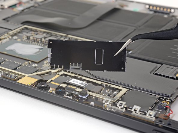
– Pop off the heat sink shield—carefully now, you’re just removing the armor, not battling a dragon.
Step 29

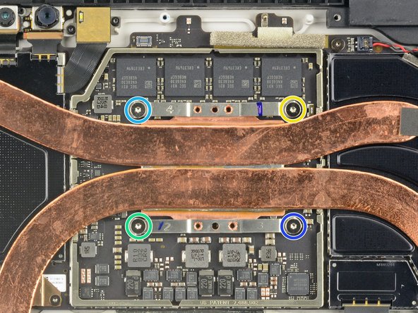
– Time to tackle the heat sink! First, pop out those ten Torx screws holding it in place:
– When you’re putting the heat sink back, give those screws a good criss-cross tightening—one turn at a time until they’re snug as a bug:
– Here’s the crew to look out for: Five 2.6 mm T3 screws and Four 3.3 mm T5 screws.
– Remember our trusty Screw Buddies? Let’s tighten them in this order: Screw 1, Screw 2, Screw 3, Screw 4.
Step 30


Handle the heat sink pipes with care—no dents, no creases, just smooth moves!
– Grab the flat end of your trusty spudger and carefully nudge the heat sink straight up and off the CPU—easy does it, no need to rush!
– When it’s time to put things back together, don’t skimp on the cleaning. Give the heat sink and CPU a good cleanse, and be sure to spread some fresh thermal paste for that cool-factor these components deserve.
Tools Used
Step 31

Avoid bending the shield too much—it’s gotta go back in during reassembly, and we want it looking sharp!
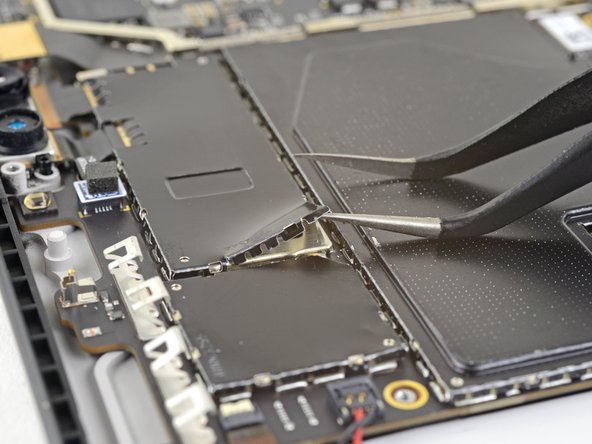
– Slide the tip of a pair of pointy tweezers into the corner gap of the EMI shield that’s snug over the camera connectors.
– Gently wiggle and pry that EMI shield away from the motherboard—be patient and try not to bend it too much, we don’t want any drama here.
– Work your magic at different spots around the shield until it pops free. Once it’s loose, take it off like a pro.
Tools Used
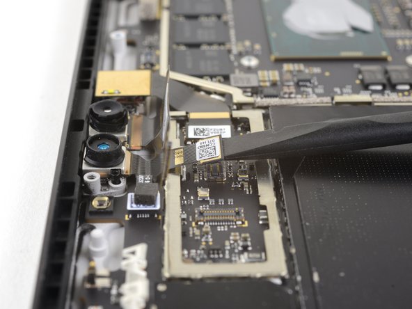
Step 32

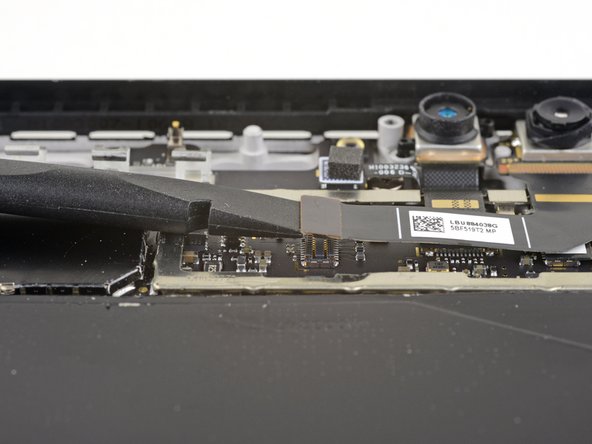
– Grab the flat end of a spudger and gently pop that front-facing camera connector up and out of its cozy little socket on the motherboard.
Tools Used
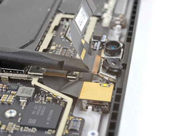
Step 33

– Grab your trusty spudger and use its flat end to gently pop the face-detection camera connector out of its cozy little socket on the motherboard. Take it slow and steady—you’ve got this!
Tools Used
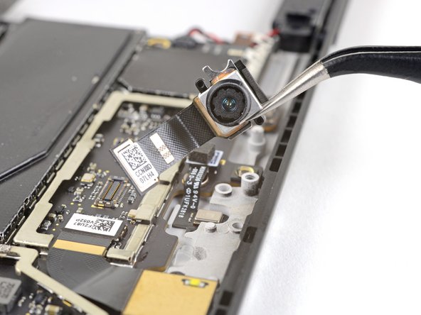
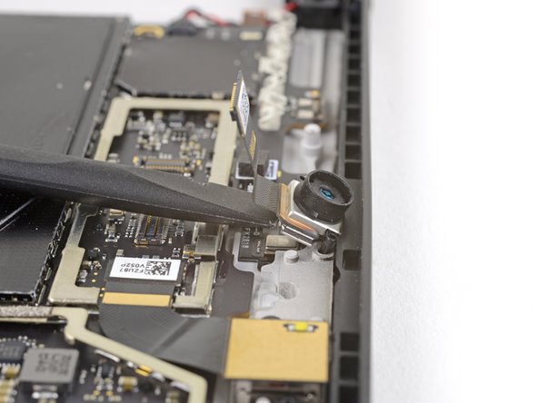
Step 34


– Gently slide the flat end of a spudger under the main front-facing camera to pop it out of its cozy spot in the case.
– Carefully take out the main front-facing camera.
Tools Used
Step 35

– Match up the new part with the original—check if you need to move over any leftover pieces or peel off adhesive before getting it all set up.
– Put your device back together by reversing the steps. It’s like rewinding your favorite DIY adventure!
– Don’t toss that old part! Drop it off at an R2 or e-Stewards certified recycler and give it a proper send-off.
– If the repair didn’t vibe with your plans, troubleshoot like a pro or swing by our Answers community for tips and tricks.
– Need an extra hand? You can always schedule a repair if things get tricky.