C. BLV NeoPixel Board
Duration: 45 minutes
Steps: 5 Steps
Rolling with RRF3? Time to update the BLV NeoPixel board before moving on. Let’s get that upgrade sorted!
Step 1

Unplug those TX/RX wires from the Duet—set them free!
Once you’ve snagged the CH340 Driver from the FYSTEC Github and got it installed, you’re on the right track!
– First things first, add a jumper to connect ‘UVCC to 5V’. Skipping this step means you’ll be stranded when trying to flash the board, so don’t skip it!
– Next up, grab the sketch from Github, unzip that package, and open it up in Arduino IDE. Think of it as loading your favorite playlist before a jam session.
– Hit the upload button and let the magic happen—your sketch will transfer to the board.
– Once the upload wraps up, remove the jumper you added earlier. Easy peasy!
– Your board is an ‘Arduino Pro or Pro Mini’, and it’s rocking an ‘ATmega328P (5V, 16 MHz)’ processor—just like in the instructions.
– If you need help along the way, you can always schedule a repair.
Step 2


– Connect the Left (Heatbed) wire to port #3 on the BLV NeoPixel board, the Middle (Hotend) wire to port #1, and the Right (Print Status) wire to port #2. Keep things tidy and make sure each cable goes to its designated port. If you need help, you can always schedule a repair.
Step 3

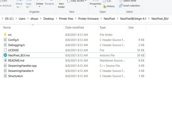
– If you see an error that says something like “NeoPixel_BLV.ino needs to be in a folder named NeoPixel_BLV,” don’t worry, there are a couple of ways to sort this out.
– One option is to create a new folder and move the sketch into that folder. Click OK, then close Arduino IDE. Next, move the files and folder into the newly created “NeoPixel_BLV” folder. After that, reopen the sketch and you should be good to go—no more errors!
– Alternatively, you can simply rename the folder that contains the sketch to “NeoPixel_BLV”. Once you do that, open the sketch and you won’t see that error again.
Step 4


– Since the CH340’s RX line hits around 4.5V, it can’t talk properly with the Duet 3. To fix this, you’ll want to cut the trace or de-solder the pad on either the green CH340 or the red ATMega. I recommend de-soldering the CH340 pad—it’s usually easier to handle.
– Along with the wiring schematic, make sure to connect the Arduino’s TX to the Duet’s RX pin.
– After making these changes, you’ll need to use a FTDI serial adapter to upload sketches via the USB port, connecting it to the six-pin header next to the USB port.
– Connect Arduino RX to Duet 3 io1.out.
– Connect Arduino TX to Duet 3 io1.in.
– Connect Arduino GND to Duet 3 io1.GND.
Step 5
– If you’re rocking a firmware version before RRF 3.4, this one’s for you!
– Got RRF 3.4 or a newer version? Then this applies to you.
– Using IO_0? Set it up with M575 P1 S1 B57600.
– If IO_1 is your jam, go with M575 P2 S1 B57600.
– On IO_0? Use M575 P1 S0 B57600 for smooth sailing.
– For IO_1, it’s M575 P2 S0 B57600 to keep things running smoothly.
Success!
