Step-by-Step Nintendo GameCube Teardown Guide
Duration: 45 minutes
Steps: 8 Steps
Launched in 2001, the Nintendo GameCube was the second most powerful gaming console of its era, even though it didn’t come with any fancy multimedia features. It was my very first stationary gaming device, and I still have a soft spot for it, especially since it hosts some amazing games like Zelda: The WindWaker and the ultimate version of Resident Evil 4. The unit we’re taking apart in this teardown is a PAL model. So, let’s dive in and enjoy the teardown!
Step 1


– Flip the device over, and grab your 4.5mm gamebit driver to unscrew the four deep screws tucked away in the corners. But hold off on removing the enclosure for now!
– Now, flip the device back to its regular position and gently lift off the top case. It should come up with little effort.
Step 2


– Gently pop off the controller port cover and the back I/O cover by releasing the two snaps on each side. Hold off on removing the controller panel just yet.
– Next up, let’s tackle those heatsinks on the memory card slots—this step is a must!
Step 3


– Let’s kick things off by taking out those regular Phillips #2 screws!
– First up, we need to remove the fan assembly.
– Next, go ahead and unscrew the 12 visible screws that are hanging out around the edges of your now not-so-cube-shaped GameCube.
Step 4

– Time to get your hands dirty, it is now possible to lift the drive assembly up. You may need to give it a bit of encouragement with a screwdriver or a trusty heavy duty spudger.
– Woohoo, the mainboard is now visible – that was the tough part, now you are making great progress!
Tools Used

Step 5

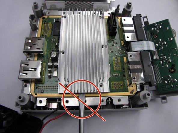
Heads up! When lifting the heatsink, be gentle and cautious with your tool. If it’s being stubborn, try warming up those thermal pads with a hairdryer or heat gun and give it a little twist by hand. If you need help, you can always schedule a repair
– First up, let’s get that heatsink off! Unscrew the six screws that are keeping it in place.
– Next, grab something flat and sturdy. Gently slide it under the aluminum of the heatsink and use it as a lever to lift it up carefully.
Step 6


– Got some thermal pads hanging out on those processors or RAM chips? No worries! Just grab a plastic spudger and gently pry them off. Easy peasy!
– Next up, it’s time to disconnect the controller port panel connector. Just lift it up and give it a little jiggle—should pop right off without a fuss!
Tools Used
Step 7


– Let’s start with the specs: 24 MB MoSys 1T-SRAM – that’s some serious tech!
– Next up, we’ve got the ATI ‘Flipper’ GPU, running at 162 MHz with 3 MB 1T-SRAM embedded within the die – talk about a powerhouse!
– The brain of the operation is the IBM ‘Gekko’ CPU, clocking in at 486 MHz with a PowerPC 750CXe-based core – nice and speedy!
– Now, let’s take a look at the connectors (check out that 2nd pic!):
– ‘Hi Speed Port’ – because who doesn’t love a little speed?
– ‘Serial Port 1’ – the first of two, but just as important!
– ‘Serial Port 2’ – the dynamic duo of serial ports is complete!
Step 8
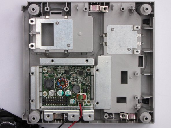


– If you’re having trouble prying up the mainboard, don’t stress – gently lift it up and check out the metal plate underneath, likely serving as an EMI shield. You’ll need to remove the two screws that hold it in place. Once you’ve done that, you’ll get access to the internal power supply.