Nintendo GameCube Laser Replacement Guide
Duration: 45 minutes
Steps: 17 Steps
So, your Nintendo GameCube isn’t feeling well and can’t read those awesome discs anymore? No worries! This guide will walk you through the process of replacing the Optical Laser Lens. Before we dive in, just make sure your GameCube is completely powered off and unplugged from any power source. Let’s get started and bring your GameCube back to life!
Step 1


– Flip that Gamecube over so the bottom side is chillin’ up top.
– Grab your trusty 4.5 mm Gamebit screwdriver and unscrew all four screws like a pro!
Step 2


– Flip that GameCube over so the bottom’s facing up, and once you’ve removed the screws, gently lift the outer shell away from the top half—easy does it!
– Now, position the GameCube so the inside is facing up, and you’re all set to keep going!
Step 3

– Give the clips on both sides of the back panel a gentle push down to release them.
– Carefully lift the back panel off the GameCube and set it aside.
Step 4

Heads up! There’s a ribbon cable (marked in orange) still connected to the unit. Leave it be—no need to unplug this little guy.
– Pop off the controller ports at the front of the console—give it a little nudge, nothing too wild.
– These ports are where your controllers connect to the console. They’ve got that cool half-circle vibe, so you can’t miss them!
Step 5


Depending on what you’re aiming for, this step might not be a must-do!
– Grab your trusty Phillips #2 screwdriver and unscrew the two little guys sitting on the back of the control port. Easy peasy!
– Gently ease apart the gray outer casing from the control port and the circuit board. Take it slow—this is a no-rush zone!
Tools Used

Step 6


Keep the red and black cooling fan wire connected to the main unit—it’s boxed in orange for a reason, so don’t mess with it!
– First, take a look at the left side of your unit – that’s where you’ll find the cooling fan and its housing, just chillin’ and keeping things cool.
– Now it’s time to get a little hands-on: carefully remove the two screws that are holding the cooling fan housing in place. Easy does it!
Step 7


– Let’s get started! Remove the four Phillips #1 screws that hold the ground springs in place.
– Gently pry the ground springs away from the main unit – they’re coming out!
Step 8


– The optical drive is fastened to a sturdy metal plate.
– Grab your Phillips #2 screwdriver and carefully remove the twelve screws lining the outer edge of the optical drive. They’re keeping it snug, but you’ve got this!
Tools Used
Step 9


– Gently pry apart the optical drive assembly from the GameCube unit, taking your time to avoid any mishaps.
– The optical drive assembly is held in place by a slot on the motherboard underneath, so you might need to apply a bit of force to release it carefully.
– Don’t worry, the metal plate and the actual optical drive will stay connected, so you’re in the clear!
Step 10


Handle that brown ribbon cable with care—it’s delicate, so go slow and steady!
– Alright, by now, your optical drive assembly should be chilling on its own, separate from your GameCube.
– Flip that optical drive assembly upside down—give it a new perspective on life!
– Grab your trusty Phillips #1 screwdriver and unscrew the six screws holding things together.
– Now, carefully lift off the metal plate and set it aside. Boom, you’re making progress!
Tools Used

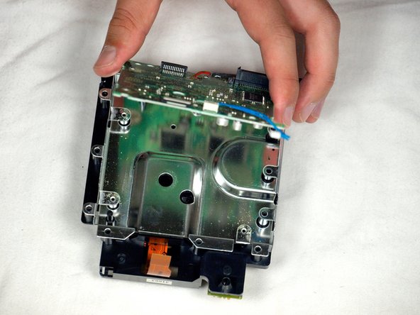
Step 11


Be gentle! Avoid pulling on the wire or the connector attached to the board, as this could cause damage.
– Gently pull out the blue wire. Easy peasy, no stress here!
– Carefully disconnect the brown cable. To do this, pull the black tab away from the white plastic—this will loosen things up, and the brown cable will slide out smoothly and effortlessly.
– Unscrew the four Phillips #1 screws that are holding the circuit board in place with the optical drive assembly. Keep those screws safe; they’re tiny but important!
– Heads up! The fourth screw is a little sneaky—it’s hiding behind the screwdriver in the third picture. Don’t let it outsmart you!
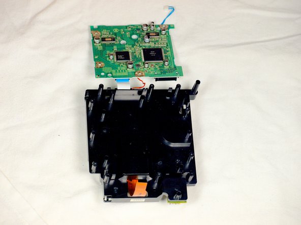
Step 12


Keep those red wires and white ribbon cable buddies connected! Seriously, no separating the circuit board from the metal plate here.
– Pop open that tiny clip like a pro—it’s holding the board snug.
– Carefully lift out the circuit board (yep, the big green square). Follow the cool trio of pics to see how it’s done!
– The red wire is your buddy here—handle it gently.
– Don’t forget the white ribbon cable—it’s delicate but oh-so-important!
Step 13


– Grab a flathead screwdriver and gently pop off the four plastic clips holding the drive assembly together. Take it slow, no rush here!
– Now, carefully use the screwdriver as a lever to unscrew and release the last clip. It’s almost done!
Step 14


Heads up! Keep those steady hands and avoid cutting the red wire or yanking the white ribbon cable still linking the two halves of the drive assembly.
– Carefully lift the metal plate away from the drive assembly, no need to rush, just take your time.
– Now, gently flip the two halves of the drive assembly over, like you’re turning a page in a book.
Step 15


Watch out! Don’t let the red wire or the white ribbon cable pop loose—they’re still hanging on.
– Grab a flathead screwdriver and pop loose the two clips chillin’ on the back half of the drive assembly.
– Skip the drama with the last clip—it doesn’t need to budge. The top half of the drive assembly will slide off from the lower half, no sweat.
– Wrap it up by fully removing the top half of the drive assembly from the base.
Step 16


– Once the top part of the drive assembly is free, give it a little flip upside down.
– Grab your trusty Phillips #1 screwdriver and gently unscrew the last three screws near the lens assembly bars.
– Now, take out those three screws and carefully lift off the lens assembly.
Tools Used
Step 17

– After gently removing the laser lens from the optical drive assembly, slot in the new laser and reassemble everything by following these steps in reverse. If you need help, you can always schedule a repair.
Success!