Super Nintendo Home Console Guide: DIY Repair
Duration: 45 minutes
Steps: 19 Steps
Ready to make your Super Nintendo region-free and add some cool new LED lights? This guide helps you do just that—no switch required! Heads-up, though: this mod won’t work on 1 Chip SNES or SNES Mini. Let’s dive in and give your console a fresh update!
Step 1

– Take out the two Phillips 11.6mm screws holding the front shield to the motherboard—time to free that shield!
Step 2

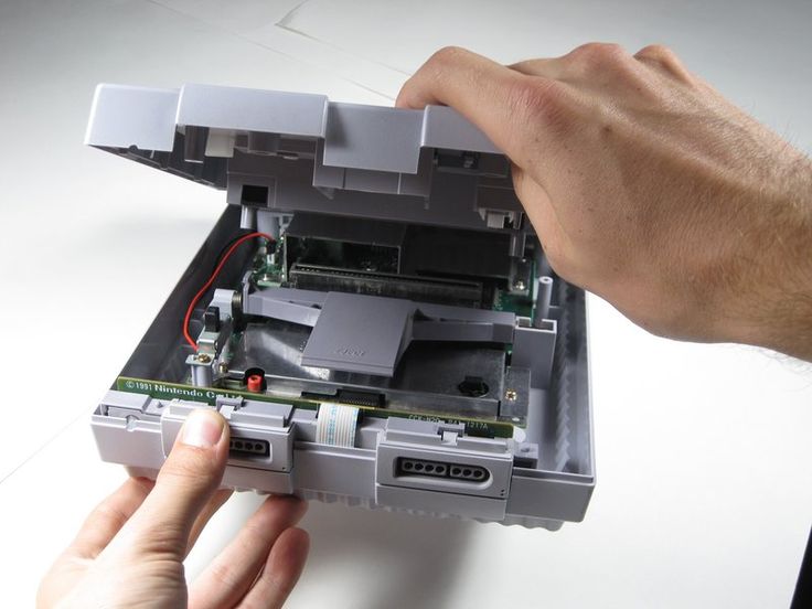
– Gently lift the front shield straight up to free it from the motherboard. You’ve got this!
Step 3

– Take out the two shiny 15.6 mm Phillips #2 screws hanging out on either side of the 62-pin connector. Easy peasy, right?
Step 4

– Unscrew the 11.8 mm Phillips #2 screw hanging out near the back of the SNES. It’s time to let it go!
Step 5

– Time to set that motherboard free! Carefully lift it straight up and out of the way.
Step 6

This mod is designed exclusively for the original Super Nintendo with 2 Chips. Unfortunately, it won’t be compatible with the 1 Chip SNES. Keep it old school and you’ll be golden!
– Let’s Get Started with Those Two Essential Chips for Your Super Nintendo!
Step 7


Got some leftover solder? No problem! Just grab your soldering iron and some solder wick, and you’ll be good to go. Gently use the wick with the iron to soak up any excess solder, leaving everything nice and clean. It’s a smooth move for a clean finish!
– Pop off that Lock Out chip like a pro (grab your trusty solder gun for this part).
– Once you’ve evicted the chip, you’ll likely see some leftover solder hanging around. Do your best to clean it up nice and smooth!
Tools Used

Step 8


– Time to get this repair started! Carefully lift up the PPU2 Pin 30 from the Motherboard
Step 9


– Now it’s time to lift up Pin 24 on PPU 1 – let’s get this repair started!
Step 10

Grab your trusty Soldering Iron and get those pins wired up like a pro!
For a little extra support, some tape can help keep those wires snug against the motherboard.
– Link up the lifted pins (PPU 2 Pin 30 & PPU1 Pin 24) together like a pro—steady hands and focus are key!
Tools Used
Step 11

– Alright, time to grab that PIC16F630 chip and pop it into the programmer. Load it up with the Super CIC file—it’s like giving it a mini superpower upgrade!
– You can snag the file right here: http://sd2snes.de/files/supercic.zip. Easy peasy!
Step 12


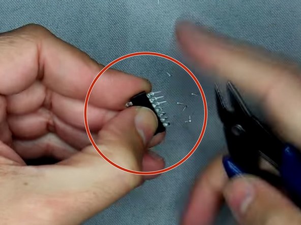
– Gently bend those pins outwards – you got this!
– Next, clip the pins into place, easy does it!
– Now, grab some double-sided tape and stick it on top of the CPU. Then, carefully place the Super CIC on top of the tape, and you’re one step closer to a fixed device!
Step 13

– Pic 1: Grab your soldering iron and connect a wire from Super CIC Pin 12 to PPU1 Pin 24. Nice and steady—you’re doing great!
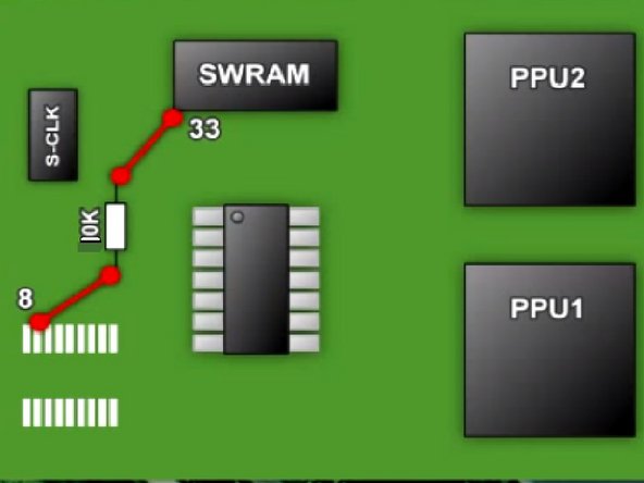
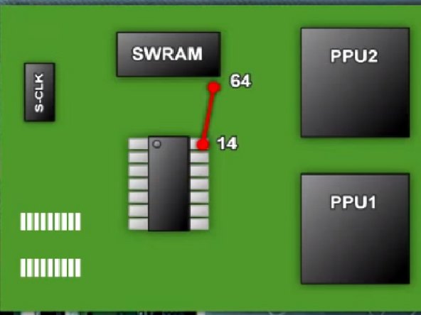
– Pic 2: Next up, solder a wire from Super CIC Pin 14 to SWRAM Pin 64. Keep it smooth, you’ve got this!
– Pic 3: Carefully attach a 10k Ohm Resistor to pin 8 (where the old CIC used to be) and link it to SWRAM Pin 33. Almost there!
Step 14


– Pic 1: Let’s get our soldering skills on point! Connect a wire from Super CIC Pin 1 to Pin 4 on the same chip. You’ve got this!
– Pic 2: Time to make some magic happen! Solder a wire from Super CIC Pin 1 to CPU Pin 1. Easy peasy!
– Pic 3: Almost there! Solder a wire from Super CIC Pin 13 to the End Point of the Resistor. Keep going, you’re doing great!
Step 15

– Pic 1: Solder a wire from Super CIC Pin 2 to S-CLK Pin 6.
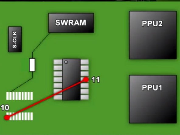
– Pic 2: Solder a wire from Super CIC Pin 11 to Old CIC Pin 10.
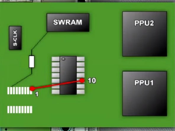
– Pic 3: Solder a wire from Super CIC Pin 10 to Old CIC Pin 1.
Step 16


– Pic 1: Connect a wire from Super CIC Pin 9 to Old CIC Pin 2, and let’s keep that connection strong!
– Pic 2: Now, let’s link a wire from Super CIC Pin 8 to Old CIC Pin 11. You’re doing great!
– Pic 3: Awesome job on the soldering! You’ve tackled most of the wires. Now, let’s move on to the LED Mod!
Step 17
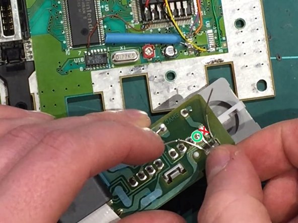

Don’t solder the middle pin on the LED Light to the right solder hole—unless you want your light stuck rocking just one color!
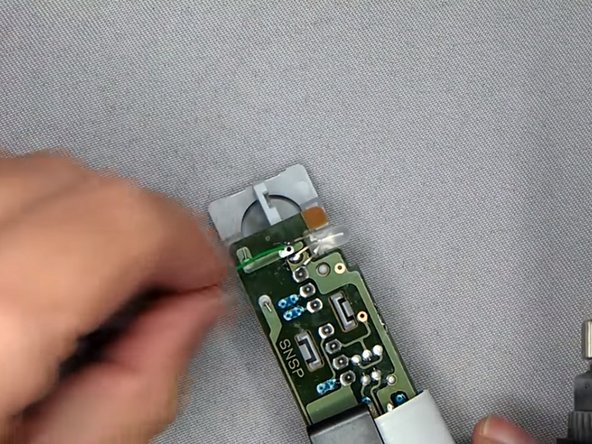
Once you’ve successfully desoldered those little points, grab your tweezers and gently pull out that LED light like a pro!
– Time to get started! First, carefully unplug the controller ports – we don’t want any unexpected power surges. Then, use your soldering skills to remove the old LED Light, making sure to release it from the middle pin on the left solder hole.
– Now it’s time to shine – literally! Solder the new LED Light into place, making sure it’s securely attached to the middle pin on the left solder hole. You’re doing great!
Tools Used

Step 18

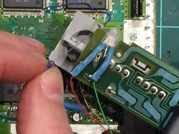
– Grab your soldering iron and connect two wires to the left and right pins of the LED light. Use a green wire for the left pin and a red wire for the right pin—color coding like a pro.
– Next, slide each wire into its own heat shrink tube. Once positioned over the pins, use some heat magic to shrink those tubes snugly in place.
– Now it’s time to flex your resistor skills: solder the 2k resistor to the red wire and the 220-ohm resistor to the green wire. Resistor dance complete.
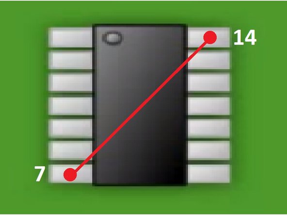
– Finally, connect the dots by soldering a wire from Super CIC Pin 7 to Pin 14. And voilà—you’ve got it!
Step 19


– To put your device back together, just work through these steps in reverse—it’s like rewinding a movie, but cooler.
– The snapshots in this guide come from a couple of videos, but hey, we thought a step-by-step guide like this would save you from sitting through a 30-minute clip. Pictures speak louder than words, right?
– If you hit a snag or just don’t feel like tackling this yourself, you can always schedule a repair with us at Salvation Repair—your device will be in good hands!
Success!