How to Replace Nintendo Switch Lite Joystick: Step-by-Step Guide
Duration: 45 minutes
Steps: 35 Steps
Ready to tackle that pesky right joystick on your Nintendo Switch Lite? Say goodbye to the infamous “Joy-Con drift” with this easy-to-follow guide! While the Switch Lite prefers JIS screws, a Phillips screwdriver will do the trick in a pinch—just be gentle to avoid stripping them. Our Phillips bits are your best buddies when it comes to JIS-style screws. Heads up: you’ll need to remove the shield plate and heat sink, and don’t forget to clean off the thermal paste from both components and the CPU before slapping it all back together. If you find yourself stuck at any point, don’t hesitate to schedule a repair!
Step 1

Before diving into this repair adventure, ensure your device is completely powered down. Let’s keep it safe and sound!
As you dive into this repair, keep tabs on every single screw and make sure each one finds its way back to exactly where it came from—no screw left behind!
– Let’s get started! Use a Y00 screwdriver to remove the four 6.3mm-long screws that hold the back panel in place. This is the first step in opening up your device, and it’s a breeze!
Step 2


To keep those pesky screws from getting stripped, press down firmly, take your time, and if they’re being stubborn, try switching up your screwdriver. You’ve got this!
– Grab your trusty JIS 000 driver or the official iFixit PH 000 driver, and let’s get those screws out! We’re looking to remove the screws holding the back panel in place:
– First up, tackle the two 3.6 mm-long screws located at the top of the device.
– Next, don’t forget about the two 3.6 mm-long screws at the bottom of the device.
Step 3


Be careful not to poke the opening tool in too far, or the speaker module might not be too happy about it!
– Gently slide an opening tool into the left speaker grille at the bottom of your device.
– Give that opening tool a little twist to pop those clips holding the back panel in place.
Step 4


– Take your trusty opening tool and glide it smoothly along the bottom-left corner to pop those clips free on the left side of your device. Keep it steady, you’ve got this!
Step 5


Be careful not to poke the opening tool too deep! Gotta protect that speaker module!
– Gently slide an opening tool into the right speaker grille at the bottom of your device.
– Give that tool a little twist to pop those clips loose!
Step 6


– Gently rock that opening tool around the bottom-right corner and work your way up the right side of the device to pop those clips loose. You’ve got this—keep it steady and smooth!
Step 7


– Keep working that opening tool along the top edge of the device, sliding and prying to pop those clips loose like a pro.
Step 8


– Gently lift up the bottom edge of the back panel, swinging it open like you’re flipping to your favorite chapter in a book.
– Carefully take off the back panel and set it aside. Easy-peasy!
Step 9

– Grab your trusty JIS 000 driver or the official iFixit PH 000 driver and let’s tackle those screws! You’ll need to remove four of them:
– Three screws measuring 3.1 mm
– One screw that’s 4.5 mm
Step 10


You might feel a bit of pushback here—totally normal! That shield plate is just hanging out with the heat sink, bonded by a little thermal paste.
– Grab your spudger or your trusty fingers and lift that shield plate out of the device. It’s go time!
– Say goodbye to the shield plate. Out it goes!
– Wipe away the old thermal paste from both the shield plate and heat sink with isopropyl alcohol and a microfiber cloth. Freshen things up by applying new thermal paste to the heat sink before reassembly.
Tools Used


Step 11


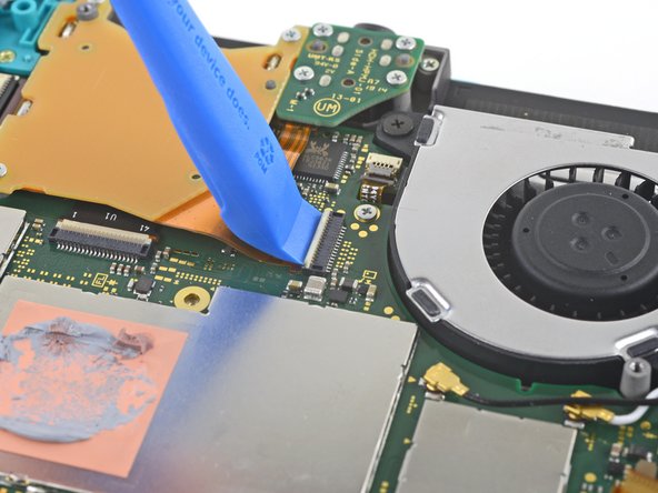
– Grab your trusty opening tool or just your fingernail and gently lift that little hinged locking flap on the motherboard interconnect cable’s ZIF connector. You’ve got this!
Step 12


Keep metal tweezers out of the picture! Some say they can cause a short circuit with the ribbon cable or connector. Nylon or ceramic-tipped tweezers are a safer bet to avoid any surprises.
– Grab your trusty tweezers and gently wiggle the interconnect cable out of its cozy home in the motherboard connector. You’ve got this!
Tools Used

Step 13


– Gently use the tip of a spudger to lift the battery connector straight up and out of its cozy spot on the motherboard. You’ve got this!
Tools Used
Step 14

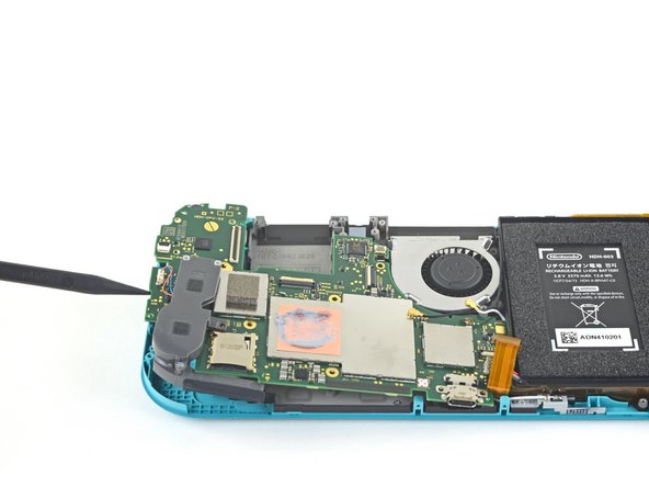
Just peel back the foam enough to give the fan some breathing room—no need to overdo it!
– Gently lift the foam that’s sticking to the fan using the flat end of a spudger or your fingers. Take your time and be careful—it’s like peeling a sticker off a new gadget!
Tools Used
Step 15

– Let’s get started! Use a JIS 000 driver or an official PH 000 driver to remove the three 3mm screws that hold the heat sink in place on the motherboard. This is a pretty straightforward step, but if you need help, you can always schedule a repair
Step 16


Don’t worry if it feels a little stuck—that’s just the heat sink playing hard to get because it’s lightly glued to the CPU with thermal paste.
– Gently use a spudger or your fingers to lift that heatsink straight up and off the motherboard—like a pro! You got this.
– Wipe off the old thermal paste from the heatsink and CPU with some isopropyl alcohol and a microfiber cloth. Then, apply fresh thermal paste to the CPU before putting everything back together. Your device will thank you!
Tools Used
Step 17

– Grab your trusty opening tool or, if you’re feeling adventurous, your fingernail! Time to gently lift that small, hinged locking flap on the ZIF connector for the game card reader cable. You’ve got this!
Step 18

– Grab your trusty JIS 000 driver or the official iFixit PH 000 driver, and let’s get those seven 3.1 mm screws off that are holding the game card reader and headphone jack in place! You’ve got this!
Step 19


– Grab some tweezers or just use your fingers and gently lift up the game card reader. Slide it to the left like a pro to wiggle the cable out of its connector—smooth moves!
– Now, take out the game card reader and headphone jack. You’re doing great, keep it up!
Tools Used
Step 20

– Grab your trusty JIS 000 driver or a PH 000 driver and carefully unscrew the two 4.5 mm screws holding the right trigger button assembly to the motherboard. Take your time—precision is key!
Step 21


– Carefully pop off the right trigger button assembly.
Step 22
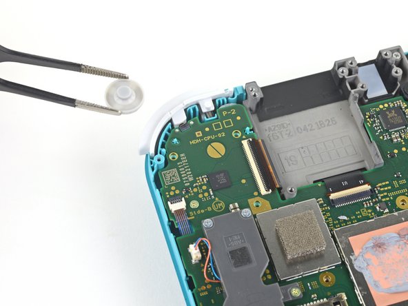

– Let’s get started! Use a pair of tweezers or your fingers to gently remove the rubber pad from the right trigger button assembly. If it’s already detached, no worries! Just set it aside for now.
Tools Used
Step 23

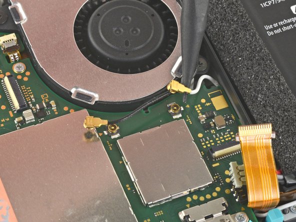

– Grab your trusty spudger and gently pop the black antenna cable straight up from its socket on the motherboard. Easy does it!
– Now, repeat the same move for the white antenna cable—you’re practically a pro at this!
Tools Used
Step 24

– Grab an opening tool (or just your fingernail) and gently pop up the tiny, hinged locking flap on the fan cable’s ZIF connector. Easy does it—you’ve got this!
Step 25


– Grab your trusty tweezers and gently nudge the fan cable out from its connector on the motherboard—easy does it!
Tools Used
Step 26


– Grab your trusty opening tool—or even just your fingernail—and gently pop up that tiny, hinged locking flap on the ZIF connector for the screen cable. Take it slow and steady, and you’ll be golden!
Step 27


– Grab a pair of tweezers and gently wiggle the screen cable out of its connector on the motherboard. Easy does it!
Tools Used
Step 28


– Take your time and use an opening tool or your fingernail to gently flip up the tiny hinged locking flap on the digitizer cable’s ZIF connector—no rush, you’ve got this!
Step 29


– Grab a pair of tweezers and gently wiggle that digitizer cable loose from its connector on the motherboard—steady hands win the race!
Tools Used
Step 30


– Grab your trusty opening tool or your fingernail and gently pop up that tiny, hinged locking flap on the right joystick cable’s ZIF connector. You’ve got this!
Step 31


– Grab your trusty tweezers and gently slide the right joystick cable out of its connector on the motherboard—easy does it!
Tools Used
Step 32

– Grab your trusty JIS 000 driver or the official iFixit PH 000 driver and let’s get to work! Start by removing the six screws that are holding the motherboard in place:
– Three screws measuring 3.1 mm
– Three screws measuring 4.5 mm
Step 33


– Use a spudger to gently wiggle into the gap between the frame and the motherboard, then carefully lift the motherboard out of its snug spot.
– Take out the entire motherboard assembly.
Tools Used
Step 34

– Grab your JIS 000 driver or the official PH 000 driver and zap out those two 3.5 mm screws holding the joystick in place.
Step 35


There’s a slim black gasket around the spot where the joystick pokes through the frame. Be careful not to mess with this little guy while you remove the joystick.
– To put everything back together, just follow these steps in reverse – easy peasy!
– Now, be kind to the planet and recycle your e-waste at an R2 or e-Stewards certified recycler.
– If things didn’t quite go as planned, try some basic troubleshooting or check out our Nintendo Switch Lite Answers community for some helpful tips. If you need help, you can always schedule a repair
– You did it! You’re now a repair rockstar!
Success!