DIY Nintendo Switch Lite Left Joystick Replacement Guide
Duration: 45 minutes
Steps: 29 Steps
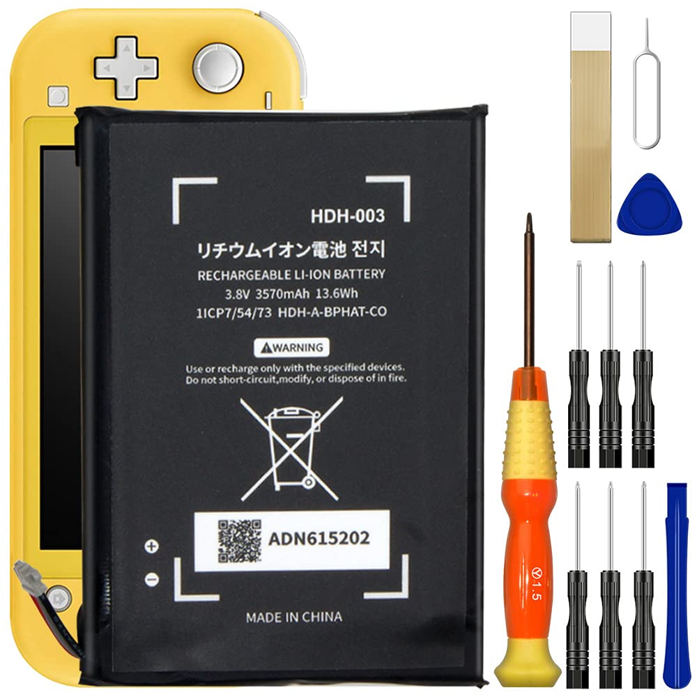
Ready to tackle the Joy-Con drift issue on your Nintendo Switch Lite? Let’s replace that left joystick and get your gaming groove back! (Need to swap the right joystick? This guide’s got you covered too.) The Switch Lite comes with JIS screws, but no worries—your trusty Phillips screwdriver will do the trick. Just take it easy to avoid stripping those screws. Pro tip: Phillips bits can work with JIS-style screws like a charm. Heads up: You’ll need to disconnect the battery for safety. To do that, you’ll first remove the shield plate, which is glued to the heat sink with thermal paste. Don’t forget to clean off the old paste and slap on some fresh stuff before putting the shield plate back in place.
Step 1

Before diving into this repair adventure, ensure your device is totally powered down and ready for action!
As you tackle this repair, keep an eye on each screw and make sure it finds its way back to its original home. You’ve got this!
– Grab your trusty Y00 screwdriver and get ready to tackle those four screws holding the back panel in place. They’re 6.3mm long, so let’s show them who’s boss!
Step 2


Don’t let those tight screws get the best of you! Apply steady downward pressure, take your time, and if they’re being stubborn, switch to a different screwdriver.
– Grab a JIS 000 driver or the official Salvation Repair PH 000 driver to pop off these screws holding the back panel:
– Two 3.6 mm screws at the top
– Two 3.6 mm screws at the bottom
Step 3


Be careful not to push the opening tool in too far, or you might accidentally damage the speaker module. Let’s keep that speaker sounding sweet!
– Slide an opening tool into the left speaker grille at the bottom of your device.
– Gently twist the tool to pop those clips and free the back panel like a champ!
Step 4


– Gently work the opening tool around the bottom-left corner to pop those clips loose on the left side of the device.
Step 5


Keep it chill and don’t push the opening tool too deep—let’s not accidentally poke the speaker module, okay?
– Gently insert an opening tool into the right speaker grille on the bottom of the device.
– Give the tool a little twist to pop those clips loose.
Step 6


– Time to get this repair started! Carefully slide and pry the opening tool around the bottom-right corner to release the clips on the right side of the device. Take your time and be gentle, we’ve got this!
Step 7


– Keep gliding and gently prying the opening tool along the top gap of your device to pop those clips loose. You’re doing great!
Step 8


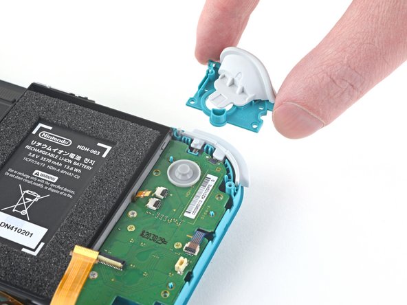
– Gently lift up the bottom edge of the back panel, flipping it open like you’re turning the page of your favorite book.
– Carefully take off the back panel and set it aside.
Step 9

– Grab your trusty JIS 000 screwdriver or the PH 000 driver from your toolkit to tackle these screws:
– Three little 3.1 mm screws
– One bigger 4.5 mm screw
Step 10


You might encounter a little pushback here, and that’s totally cool! The shield plate is just a bit snug against the heat sink thanks to some thermal paste bonding them together.
– Grab a spudger or just your trusty fingers and gently lift that shield plate right out of the device.
– Say goodbye to the shield plate as you remove it.
– Time for a little cleanup! Use some isopropyl alcohol and a microfiber cloth to wipe away the old thermal paste from both the shield plate and heat sink. Don’t forget to apply a fresh layer of thermal paste to the heat sink before putting everything back together!
Tools Used


Step 11


– Time to get that motherboard interconnect cable connected! Use an opening tool or your trusty fingernail to gently flip up the small, hinged locking flap on the ZIF connector. Easy does it!
Step 12


Avoid using metal tweezers! Some folks say that metallic tweezers can cause a short circuit in the ribbon cable or connector. It’s probably a good idea to stick with nylon-tipped or ceramic-tipped tweezers for a safer experience.
– Grab a trusty pair of tweezers and gently wiggle that interconnect cable free from its cozy spot on the motherboard. You’ve got this!
Tools Used

Step 13


– Gently use the spudger’s pointy end to lift the battery connector straight up and out of its cozy home on the motherboard. You’ve got this!
Tools Used
Step 14


Avoid pulling on the wires—yanking them might lead to a connector catastrophe!
– Time to get a little handy! Use a pair of tweezers or your fingers to gently pull the left speaker cable straight up and out of its socket on the daughterboard. Take your time and be careful not to damage the surrounding components.
Tools Used
Step 15

– Grab your trusty JIS 000 driver or the official iFixit PH 000 driver and get ready to tackle that 4.5 mm screw holding the left speaker module in place. Let’s make this repair happen!
Step 16


Be cautious! A part of the speaker module is nestled under a delicate ribbon cable. Gently does it—avoid snagging the speaker module on the cable as you take it out!
– Gently grab the speaker module with your fingers and lift it up and out of its spot—easy does it, and you’re golden!
Step 17


– Grab your trusty opening tool or just your fingernail, and gently lift that little hinged locking flap on the ZIF connector for the motherboard interconnect cable. You’ve got this!
Step 18


– Grab a trusty pair of tweezers and gently wiggle that motherboard interconnect cable out of its cozy connector on the daughterboard. You’ve got this!
Tools Used
Step 19


– Grab your trusty opening tool or a reliable fingernail and gently lift up the tiny, hinged locking flaps on those two ribbon cable ZIF connectors. You’ve got this!
Step 20


– Grab a trusty pair of tweezers and gently slide the daughterboard screen cable out of its cozy connector on the motherboard. You’ve got this!
– Now, let’s do the same for the volume buttons cable. Just a little finesse and you’ll be on your way!
Tools Used
Step 21


– Grab your trusty tweezers or just use your fingers and gently pop off the volume buttons.
Tools Used
Step 22


– Gently pop up the tiny hinged locking flap on the ZIF connector for the left joystick cable—your fingernail or an opening tool will do the trick!
Step 23


– Grab your trusty tweezers and gently slide the left joystick cable out of its snug little connector on the daughterboard. Easy does it!
Tools Used
Step 24

– Grab your trusty JIS 000 screwdriver or a PH 000 driver and unscrew the two 4.5 mm screws holding the left trigger button assembly in place. Let’s get that button back in action!
Step 25

– Gently pop out the left trigger button assembly—you’re on a roll!
Step 26

– Grab a JIS 000 driver or the PH 000 driver from your toolkit and get ready to tackle these four screws:
– Two screws, each measuring 4.5 mm
– Two screws, each measuring 6 mm
Step 27


– Use your fingers to gently lift the daughterboard and pop it out of its spot.
Step 28

– Grab a JIS 000 driver or an official PH 000 driver to unscrew the two 3.5mm screws holding the left joystick in place. It’s a quick and easy step, just make sure you’ve got the right tool for the job.
Step 29


There’s a slim black gasket around the hole where the joystick peeks through the frame. Be careful not to mess with this gasket while you take out the joystick.
– To put your device back together, just retrace these steps in reverse—it’s like hitting rewind!
– Got old tech? Drop it off with an R2 or e-Stewards certified recycler and give it a second life.
– Did things not go as planned? Don’t sweat it! Try some troubleshooting or reach out to our Nintendo Switch Lite Answers community for some solid advice.
– Need a hand? You can always schedule a repair with us!
Tools Used
Success!