DIY Guide: Nintendo Switch WiFi Antenna Replacement Tutorial
Duration: 45 minutes
Steps: 47 Steps
Step 1


Before diving into this repair adventure, make sure your device is fully powered down and ready for some TLC.
– Alright, here’s the move: find that little round button on the back of your Joy Con controller and give it a nice firm press and hold.
– While you’re holding that button down, smoothly slide the controller upward like you’re pulling off a smooth dance move. Boom, you’re golden!
Step 2


Now, just repeat the same steps for the other Joy Con and you’re golden! It’s a quick and easy process, so no worries!
– Keep sliding that Joy Con up until it pops right off the console, just like a pro!
Step 3

As you dive into this repair adventure, remember to keep an eye on each screw and return it to its rightful home when you’re done. You’ve got this!
– Grab your trusty Y00 screwdriver and let’s get to work! Carefully unscrew those four screws that are holding the rear panel in place. Each one is 6.3 mm long, so make sure to keep your eyes peeled and your tools handy!
Step 4


To avoid stripping those super tight screws, apply some firm downward force and take your time. If they’re still being stubborn, try swapping to a different JIS 000 or PH 000 driver – it might just do the trick!
– Grab your trusty JIS 000 driver or the cool official PH 000 driver from Salvation Repair and let’s get to those screws holding the rear panel:
– One 2.5 mm-long screw at the top edge of the device
– Two 2.5 mm-long screws at the bottom edge of the device
Step 5


– Grab your JIS 000 screwdriver or a PH 000 driver, and twist out the two 3.8 mm center screws hanging out on each side of the device. One on each side—it’s their time to shine!
Step 6


Got a microSD card chillin’ in the slot? Time to pop it out before moving on to the next step!
– Pop the kickstand up with your finger from the back of the device.
Step 7

– Grab a JIS 000 screwdriver or a trusty PH 000 driver and unscrew that tiny 1.6 mm screw hiding out in the kickstand well. Easy peasy!
– Now gently close the kickstand. You’re doing great!
Step 8


The game card cartridge flap is stuck to the other half of the plastic shell, so don’t try to completely lift up the rear panel if it’s closed – you won’t be able to!
– Pop open that game card flap like a pro!
– Gently lift the rear panel starting from the bottom of your device and set it aside.
Step 9

– Grab your JIS 000 screwdriver or that trusty PH 000 driver and remove the 3.1 mm screw holding the microSD card reader in place. You got this!
Step 10


– Grab your fingers or a trusty pair of tweezers and lift the microSD card reader straight up from the device—easy does it—to disconnect and remove it.
– When putting it all back together, double-check that the press connector underneath the foam pad is snugly hooked up with the motherboard. Pro tip: peeling off the foam pad first might make reinstalling the card reader a whole lot smoother!
Tools Used

Step 11

– Grab a JIS 000 screwdriver or an official Salvation Repair PH 000 driver and let’s get to work! Remove those six 3 mm screws holding the shield plate in place.
Step 12


If the foam isn’t peeling off smoothly, don’t sweat it—just take a breather and try a different angle. No need to rush; gently work around and coax it off without tearing.
– Gently peel back the foam along the top edge of your device, just by the fan exhaust port, using either your fingers or a pair of tweezers. Take your time—no need to rush!
Tools Used
Step 13


There’s a chunky pink thermal paste party going on between the shield plate and the copper heat sink below—keeping the Switch cool and chill under pressure.
You might feel a little tug when pulling the shield plate off. No worries, that’s just the thermal paste holding it together like a sticky handshake.
– Slide a spudger under the shield plate at the device’s edge—let’s get that shield moving!
– Gently pry it up to lift the shield plate and set it aside. You’re on a roll!
– If you’re careful, you can totally reuse that pink thermal compound. Just keep it tidy and ensure it makes solid contact between the heat sink and the shield when you put everything back together.
– Need to swap it out instead? No worries! Check out our thermal paste guide to remove the old thermal compound and replace it with something great, like K5 Pro, during reassembly.
Tools Used


Step 14


– Take the spudger, and gently pop the battery connector up and out of its spot on the motherboard.
Tools Used
Step 15

– Grab a JIS 000 screwdriver or a PH 000 driver and unscrew those three 3 mm screws holding the heat sink snugly to the motherboard. You’re doing awesome—keep it up!
Step 16
The foam is super delicate and can rip easily. Here’s a slick way to peel it off without drama:
Just peel the foam back enough to make room for the fan—no need to overdo it!
– Gently peel off the two foam pads stuck over the heatsink and the fan—it’s like unwrapping a gift for your device!
– Slip the tip of a spudger under the foam where it’s not glued down—be patient, this foam’s got commitment issues.
– Use your finger to press down on the top of the foam to keep it steady—show it who’s boss!
– Roll the spudger tip under the foam from one end to the other to set it free—you’re basically a foam liberation hero!
Tools Used
Step 17


You might notice a bit of pushback, but don’t worry—it’s totally normal! The heat sink and CPU are just sharing a little thermal paste bond.
– Grab a spudger or your trusty fingers and carefully lift that heatsink right off the motherboard. Easy peasy!
– Take a moment to clean off the old thermal paste from both the heatsink and the CPU using some high-octane isopropyl alcohol (90% or higher) and a soft microfiber cloth. Then show that CPU some love by applying fresh thermal paste before putting things back together.
– Spread thermal paste on every surface that originally had it—yes, that includes between the heatpipe and the aluminum shield, which the Switch cleverly uses for extra cooling. Got it? Cool!
Tools Used

Step 18


– Time to get started! Use an opening tool or your fingernail to gently flip up the small, hinged locking flap on the digitizer cable’s ZIF connector. It’s like opening a tiny door – easy does it!
Step 19


Don’t jam the cable in! If it doesn’t fit, check if the locking flap is up, adjust the cable, and try again.
Hey there! If your touchscreen acts up after the repair but the Game Card reader is good to go, double-check that this cable is snugly connected. If both the Game Card reader and touchscreen are taking a break, no worries—move on to the next step and check out the Game Card connector instead.
– Grab your tweezers and slide the digitizer cable sideways out of its connector on the game card reader board—easy does it!
– Before you pop the cable back in during reassembly, make sure the ZIF connector’s locking flap is flipped up. It’s like prepping the dance floor!
– Line up the cable nice and parallel to the board, then gently guide it into its connector. You’ve got this!
Tools Used
Step 20


If the touch screen’s being stubborn or the game cards are playing hide-and-seek after putting things back together, that press connector might not be fully clicked in. Give it a careful disconnect and reconnect—it’s like a little handshake for your device. Try it out and see the magic happen!
– Time to get this connector disconnected! Use the point of a spudger to carefully pry the headphone jack and game card reader connector straight up from the motherboard. Easy does it!
– Now, let’s get this connector reattached. To do this, carefully line it up and press down on one side until you hear that satisfying click. Then, repeat on the other side. Remember, don’t press down on the middle, or you might end up bending those pesky pins and causing some permanent damage. Take your time and get it just right!
Tools Used
Step 21

– Grab your trusty JIS 000 screwdriver or a PH 000 driver, and pop out those three 3.1 mm screws holding down the headphone jack and game card reader board. You’re doing great—keep it steady and keep it going!
Step 22


– Grab your trusty tweezers or use your fingers to gently pop off the headphone jack bracket. Easy peasy!
Tools Used
Step 23


– Gently grab your trusty tweezers or use your fingers to pop out the headphone jack and game card reader board. You’ve got this!
Tools Used
Step 24


– Grab your trusty opening tool, spudger, or even your fingernail, and gently flip up the tiny locking flap on the LCD ribbon cable ZIF connector. Easy does it—you’re doing great!
Tools Used
Step 25


– Grab your trusty tweezers and gently wiggle that ribbon cable until it pops right out of its cozy connector on the motherboard. You’ve got this!
Tools Used
Step 26


– Grab an opening tool, a spudger, or even just your trusty fingernail, and gently pop up the tiny hinged locking flap on the ZIF connector for the fan cable. Easy does it!
Tools Used
Step 27


– Grab some tweezers and gently unplug the fan cable by pulling it straight out from its slot on the motherboard. Easy peasy—just take your time!
Tools Used
Step 28


– Grab an opening tool, spudger, or even your trusty fingernail, and gently flip up the small, hinged locking flap on the ZIF connector for the power and volume button ribbon cable.
Tools Used
Step 29


– Carefully grasp the ribbon cable with a pair of tweezers and gently pull it straight out of its connector on the motherboard. If you’re not comfortable with this step, don’t worry, it’s easier than it sounds!
Tools Used
Step 30


– Grab an opening tool, spudger, or just your trusty fingernail and gently flip up the tiny hinged locking flap on the smaller LCD ribbon cable’s ZIF connector like a pro.
Tools Used
Step 31


– Grab your trusty tweezers and gently pull the ribbon cable straight out of its connector on the motherboard—easy does it!
Tools Used
Step 32


– Gently use the tip of a spudger, an opening tool, or even your fingernail to lift the small hinged locking flap on the Joy Con sensor rail’s data cable ZIF connector.
Tools Used
Step 33


– Grab your tweezers and gently pull the ribbon cable straight out of its connector on the motherboard. Easy peasy!
Tools Used
Step 34


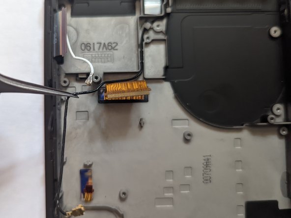
– Grab your trusty spudger and gently pop the black antenna cable straight up from its socket on the motherboard.
Tools Used
Step 35


– Grab your trusty spudger and gently pop the white antenna cable straight up out of its little socket on the motherboard—easy-peasy, just like opening a soda can (but way cooler)!
Tools Used
Step 36


Be gentle with those speaker wires – they’re super thin and can break off the connector if you pull too hard!
– Gently wiggle and pull the right speaker connector straight out of its cozy little home on the motherboard using your fingers or a trusty pair of tweezers. You’ve got this!
Tools Used
Step 37


Hey, careful now! Tugging on the connector by those skinny little speaker wires is a no-go—they’re super fragile and could snap like twigs.
– Grab those trusty fingers or a pair of tweezers and gently pull the left speaker connector straight out from its socket on the motherboard—easy does it!
Tools Used
Step 38


– Grab your opening tool, spudger, or even your trusty fingernail, and gently flip up that small, hinged locking flap on the Joy Con sensor rail data cable ZIF connector. You got this!
Tools Used
Step 39


– Grab your trusty tweezers and carefully slide the Joy Con rail data cable straight out of its connector on the motherboard—smooth moves, you’re doing great!
Tools Used
Step 40

– Grab a JIS 000 screwdriver or the cool official Salvation Repair PH 000 driver and unscrew these guys:
– Four 2.5 mm screws
– Two 3.1 mm screws
Step 41


– Slide a spudger into the gap between the motherboard and the frame with a little finesse—think of it as a delicate dance move.
– Gently lift the motherboard like you’re picking up something precious, and carefully separate it from the frame. Take your time, no rush!
Tools Used
Step 42

– Grab yourself a JIS 000 screwdriver or a PH 000 driver and take out the trio of 4.8 mm screws holding the fan in place. Keep it cool and steady!
Step 43


Double-check your new part against the original. You might need to transfer any remaining pieces (like those handy rubber bushings) to the new part before installing it.
– Grab a pair of tweezers or use your fingers, gently lift that fan straight up, and pop it out of the device like a pro.
Tools Used
Step 44

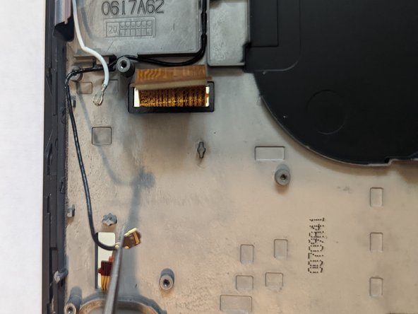
– Swing that black coax cable away from the midframe!
Step 45

– Keep tracing the wire, gently guiding it along the way. Stay focused and take it step by step!
Step 46


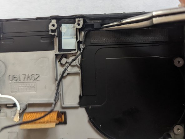
– Gently pop the metal barrel around the coax loose from the midframe—easy does it!
Step 47


– Time to set that WiFi antenna board free! Carefully grasp it with a pair of tweezers and lift straight up to remove it.