How to Replace Nintendo Switch Joy Con Sensor Rail
Duration: 45 minutes
Steps: 18 Steps
Get ready to breathe new life into your Nintendo Switch game console by replacing that broken or faulty right Joy Con sensor rail. Don’t worry if you don’t have JIS screws on hand – a Phillips screwdriver will do the trick in a pinch. Just be gentle to avoid stripping those screws. When you remove the shield plate, remember to reapply some thermal compound between the plate and the heatsink. For the best results, use a viscous thermal paste like K5 Pro, as regular thermal paste isn’t designed to fill larger gaps. This guide is compatible with both the original 2017 Nintendo Switch model and the refreshed 2019 model (HAC-001 and HAC-001(-01)).
Step 1
Before diving into this repair, double-check that your device is completely powered down. Safety first!
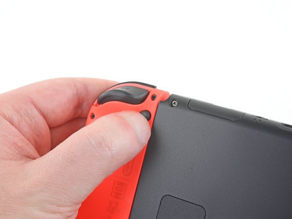
– Press and hold the small round button on the back of the Joy Con controller.
– While keeping that button held down, gently slide the controller upwards. Easy does it!
Step 2
Now it’s time to get the other Joy Con in on the action – repeat the same steps you just completed to get it ready to go!
– Slide the Joy Con upward smoothly until it pops off the console, leaving you one step closer to success!
Step 3
As you tackle this repair, be sure to keep an eye on each screw and return it to its original spot when you’re done. You’ve got this!
– Grab a Y00 screwdriver and unscrew the four 6.3mm screws holding the rear panel in place. You got this!
Step 4
To avoid stripping those super tight screws, use some elbow grease and apply firm downward force. Take your time, and if they still won’t budge, try switching to a different JIS 000 or PH 000 driver. You got this!
– Grab your JIS 000 driver or trusty PH 000 driver and get ready to unscrew some tiny screws to free the rear panel:
– First up, there’s one 2.5 mm-long screw hanging out on the top edge of your device.
– Next, tackle the two 2.5 mm-long screws chilling on the bottom edge of the device.
Step 5
– Grab your trusty JIS 000 screwdriver or a cool PH 000 driver to unscrew those two 3.8mm center screws on each side of the device. One on each side—easy peasy!
Step 6
Got a microSD card in the slot? Go ahead and pop it out now before moving on to the next step.
– With a gentle nudge from your finger, pop up the kickstand on the back of your device and give it a little lift!
Step 7
– Grab yourself a JIS 000 screwdriver or a PH 000 driver to unscrew the 1.6 mm fastener chilling in the kickstand well.
– Fold the kickstand back into place with a smooth move.
Step 8
The game card cartridge flap is like a little gate that connects to the other half of the plastic shell. If it’s closed, it makes it tricky to lift the rear panel all the way up.
– Pop open that game card cartridge flap like a pro!
– Gently lift the rear panel starting from the bottom of your device, and off it goes!
Step 9
– Grab your trusty JIS 000 screwdriver or the PH 000 driver and unscrew that 3.1 mm bad boy holding the microSD card reader in place. Steady hands, you’re doing awesome!
Step 10
– Grab your fingers or a trusty pair of tweezers and carefully lift the microSD card reader straight up to disconnect and remove it. Take it easy—no rush!
– When piecing it all back together, double-check that the press connector under the foam pad is snugly connected to the motherboard. If the foam pad is in the way, peel it off gently before popping the card reader back in place.
Tools Used
Step 11
– Grab a JIS 000 screwdriver or a PH 000 driver and twist out those six 3 mm screws holding the shield plate in place. You’ve got this!
Step 12
If the foam isn’t peeling away like butter, no worries—just don’t get rough with it, or it could rip. Gently try lifting it at different spots until it starts to come loose.
– Gently use your fingers or a pair of tweezers to lift up the foam piece at the top edge of the device near the fan exhaust port—easy does it, you’re doing great!
Tools Used
Step 13
A generous layer of thick pink thermal compound fills the space between the shield plate and the copper heat sink below. This little wonder helps keep your Switch from turning into a hot potato.
You might notice a bit of a tug when you’re working on it—that’s totally normal! The shield plate has a slight bond with the heat sink thanks to that thermal paste.
– Gently slide a spudger under the shield plate along the edge of the device.
– Pry up to lift the shield plate and remove it from the device.
– You can reuse the pink thermal compound if you’re careful. Keep it clean and ensure it makes solid contact between the heat sink and the shield during reassembly.
– If you need to replace it, refer to our thermal paste guide to remove the old thermal compound and replace it with an appropriate compound, such as K5 Pro, during reassembly.
Tools Used
Step 14
– Gently use the pointy end of a spudger to pop the battery connector straight up and out of its socket on the motherboard—nice and easy, like you’re plucking a delicate flower.
Tools Used
Step 15
– Grab a spudger, opening tool, or just your fingernail, and gently pop up the tiny hinged locking flap on the Joy-Con rail data cable’s ZIF connector. Take it slow and steady—you’re doing great!
Tools Used
Step 16
– Grab your tweezers and gently slide the Joy Con rail data cable out of its connector on the motherboard. Easy peasy!
Tools Used
Step 17
These screws are a bit stubborn and might not want to come out easily. To avoid stripping them, apply some steady pressure, take your time, and if they still won’t budge, try switching up your screwdriver. Patience is key here!
– Grab yourself a trusty JIS 000 screwdriver or the official PH 000 driver, and take out the four 3.7 mm screws holding the right Joy-Con rail snugly to the frame. Let’s get that rail off smoothly!
Step 18
Careful there, champ! Don’t let the rail’s data cable get caught on the device frame as you take it out.
– Time to give yourself a high-five! Compare your shiny new replacement part to the original to make sure everything matches up. You might need to transfer some leftover components or peel off any adhesive backing from the new part before installing it.
– To put everything back together, just follow these steps in reverse. Easy peasy!
– Now that you’re done, be sure to responsibly recycle your e-waste with an R2 or e-Stewards certified recycler.
– If things didn’t quite go as planned, don’t stress! Try some basic troubleshooting or reach out to our community at Salvation Repair for some extra help.
– If you need help or want to make sure everything is done correctly, you can always schedule a repair with us.


