Acer Iconia Tab A501 Motherboard Replacement Guide
Duration: 45 minutes
Steps: 20 Steps
The motherboard is like the heart of your device, connecting all its vital parts. If it’s feeling under the weather or has completely thrown in the towel, it might be time for a replacement. In this guide, we’ll walk you through the process of swapping out the motherboard for the Acer Iconia Tab A501. Let’s get started!
Step 1
Before you dive into fixing your device, make sure to power it off. Safety first, always!
– Grab a plastic opening tool and gently work your way around the back cover, starting at the volume buttons.
– Keep going around the short side near the camera and continue around the entire device.
Step 2
– Once you’ve made enough progress, just a smidge past halfway around the device, the back cover will pop off with ease!
Step 3
– Peel away all the tape from the device. It’s just a quick step, so go ahead and get it done!
Step 4
As you move on to the next step, remember to treat that motherboard with care—no squeezing too hard or scratching it!
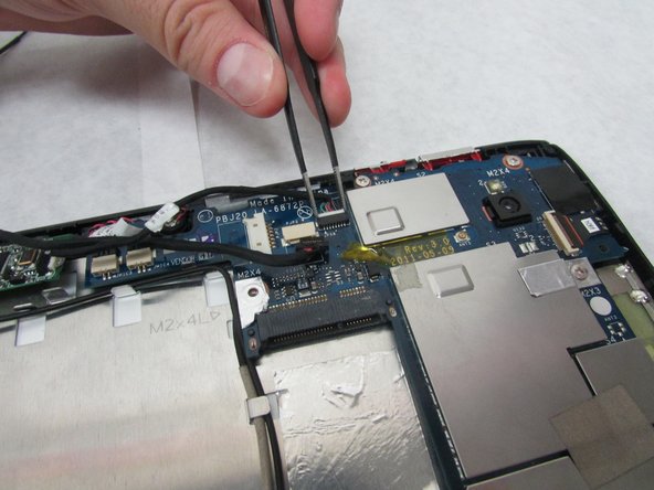
– Next, use those handy angled tweezers to carefully disconnect the motherboard-battery cable from the white connector on the side opposite the docking port – you got this!
Tools Used
Step 5
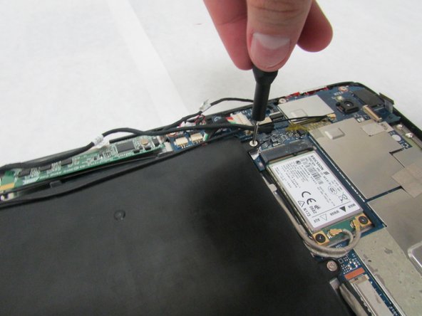
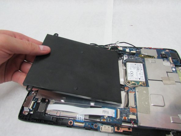
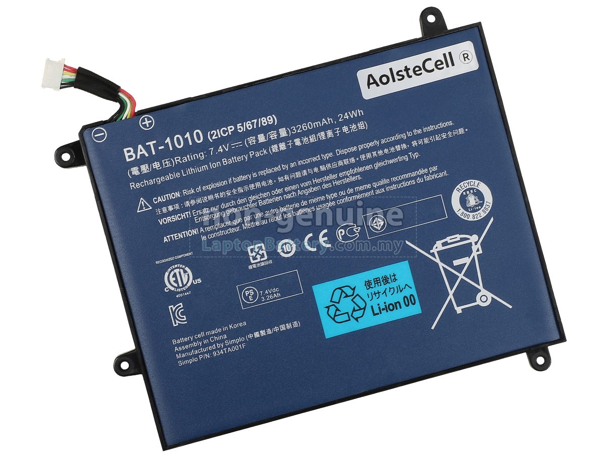
– Grab your trusty Phillips #1 screwdriver and get those four 4.0 mm screws connecting the battery to the motherboard out of the way.
– Gently lift and take out the battery.
Tools Used
Step 6
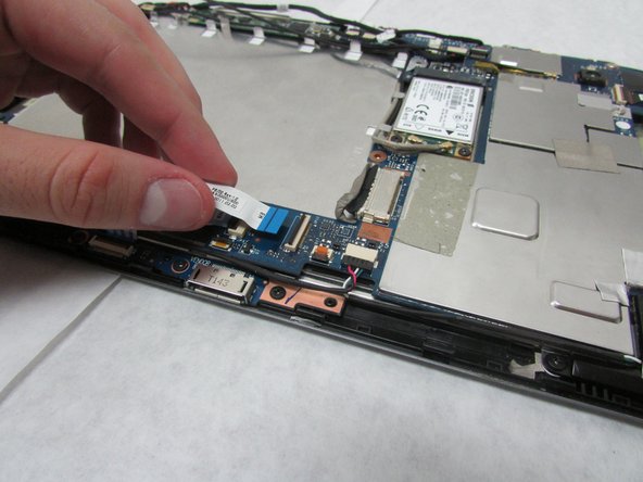
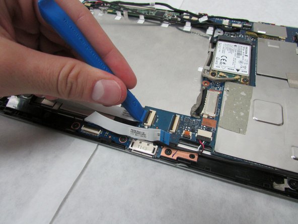
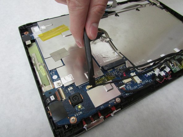
– Grab your trusty plastic opening tool and pop up the locking mechanism on the motherboard that’s keeping that folded white ribbon cable in place.
– Now, gently pull out that folded, white cable.
Step 7
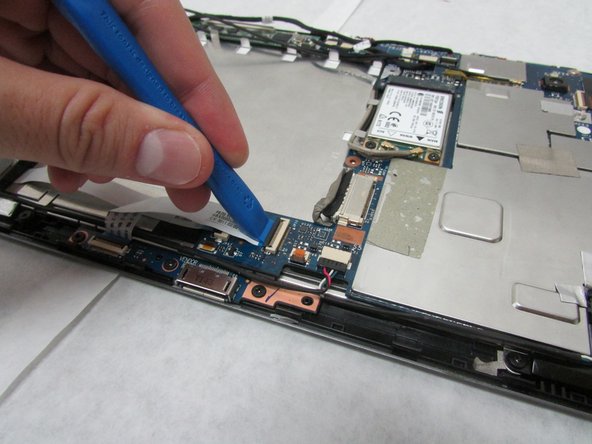
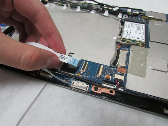
– Grab your trusty plastic opening tool and gently lift the locking mechanism on the motherboard where that straight, white ribbon cable is hanging out.
– Now, go ahead and carefully disconnect the straight, white ribbon cable. You’ve got this!
Step 8
In this step, take it easy and avoid pressing too hard or scratching that delicate motherboard. You’re doing great!
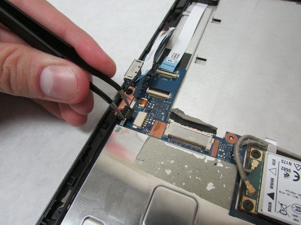
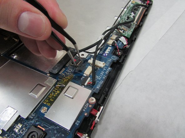
– Grab those angled tweezers and gently disconnect the cable with the red, white, and green wires from the beige connector just a smidge in from the docking port. You’ve got this!
Tools Used
Step 9
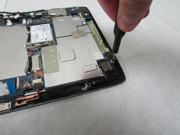
– Grab your trusty Phillips #1 screwdriver and unscrew that 3.0 mm Phillips head screw on the speaker, right by the Micro-HDMI port. You’ve got this!
– Next up, let’s tackle the 4.0 mm Phillips head screw on the speaker in the same spot. Keep that screwdriver handy!
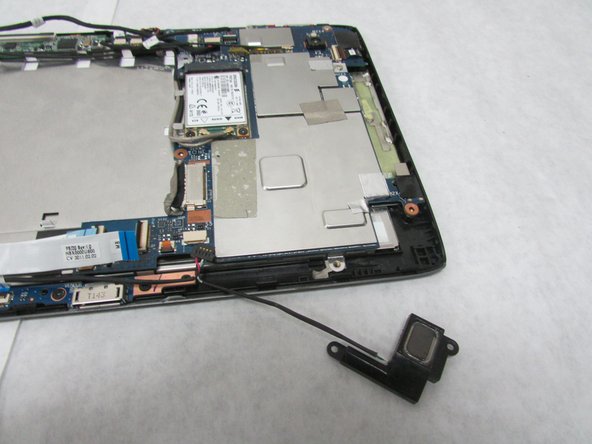
– Now, it’s time to gently remove the speaker. You’re doing great!
Tools Used
Step 10
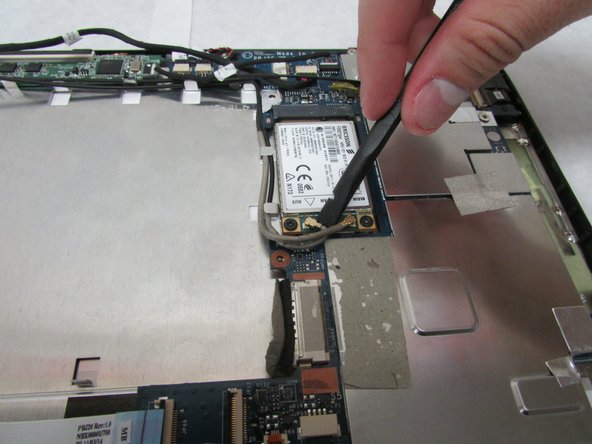
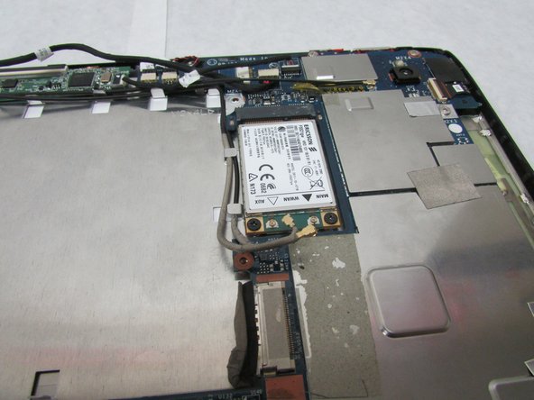
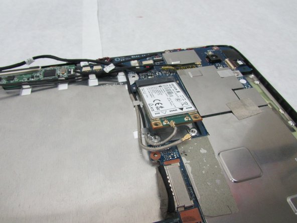
– Use the flat end of your trusty Spudger to gently pry loose the two small connectors attached to the wireless adapter. They’re tiny, but don’t worry, you got this!
Tools Used
Step 11
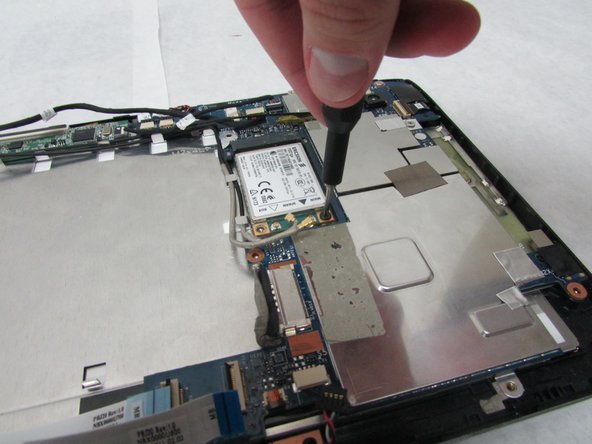
– Grab your trusty Phillips #1 screwdriver and get ready to tackle those two 3.0 mm Philips head screws that are keeping the adapter in place. Let’s get this show on the road!
Tools Used
Step 12
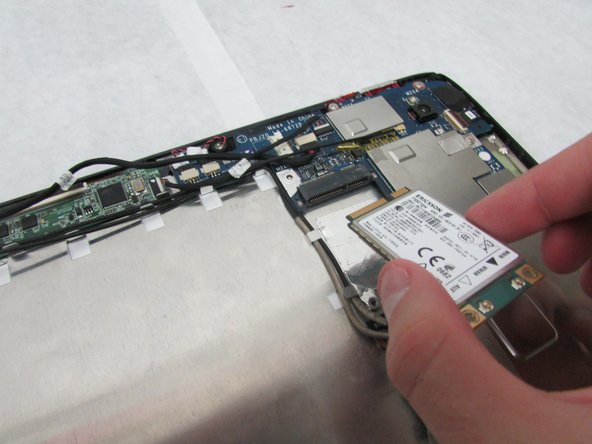
– Gently wiggle the adapter and slide it out to set it free.
Step 13
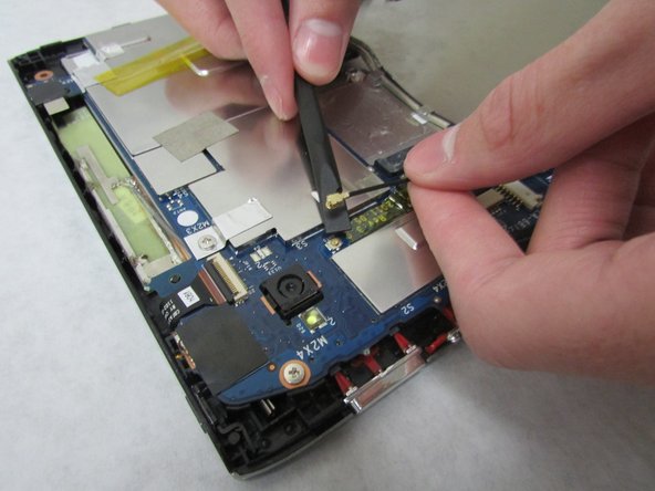
– Grab the wide end of your trusty Spudger and gently pry off the rotatable connector for the 3G antenna located just below the rear-facing camera. You’ve got this!
Tools Used
Step 14
Up next, keep it chill—don’t press too hard or accidentally scuff up the motherboard.
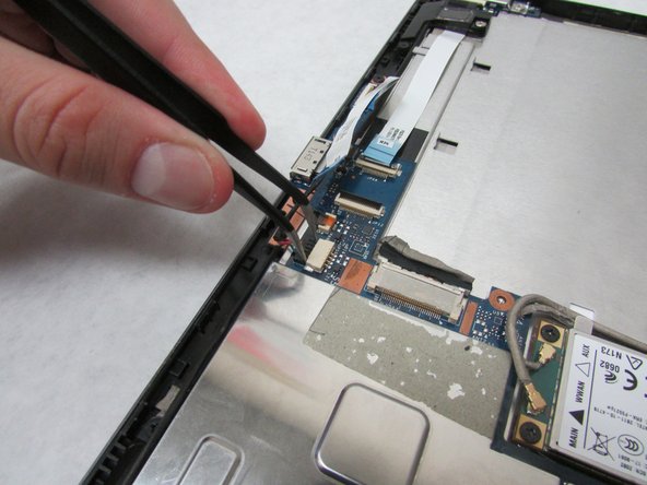
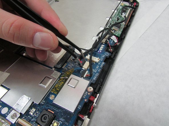
– Grab those angled tweezers and gently disconnect the cable with the red wires from the beige connector that’s hanging out near the docking port. You’ve got this!
Tools Used
Step 15
Take it easy in this step! Avoid pressing too hard or giving the motherboard any unwanted scratches.
– Time to get up close and personal with your device’s motherboard! Use those trusty tweezers to carefully remove the touchscreen connector. You got this!
Tools Used
Step 16
In this step, make sure to handle things gently—no Hulk moves here! We want to keep that motherboard looking pristine, so avoid squeezing too hard or scratching it.
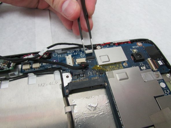
– Grab those angled tweezers and gently disconnect the two microphone connectors. You’ll find them just above the orange-brown touchscreen connector and snuggled next to the battery compartment. Easy peasy!
Tools Used
Step 17
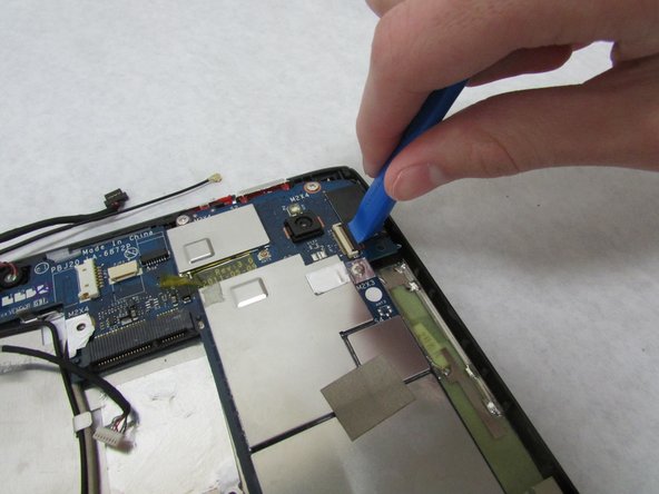
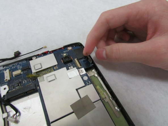
– Grab that trusty plastic opening tool and gently pop up the locking tab on the white front camera port—it’s chilling just above the rear-facing camera.
– Carefully unplug the camera cable from the motherboard like a pro, and you’re all set for the next step!
Step 18
Proceed with caution in this next step.
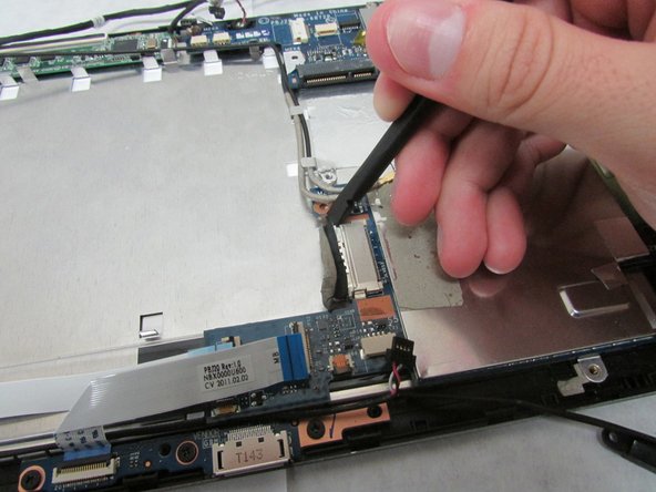
– Grab your trusty Spudger, and use its wide, flat end to gently pop the display connector loose from that big, metal port chillin’ next to the battery space.
Tools Used
Step 19
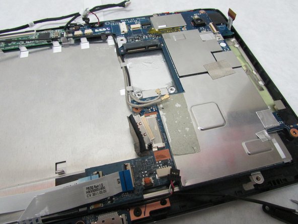
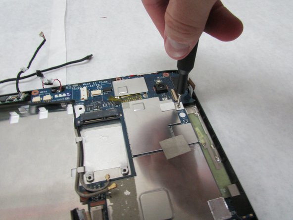
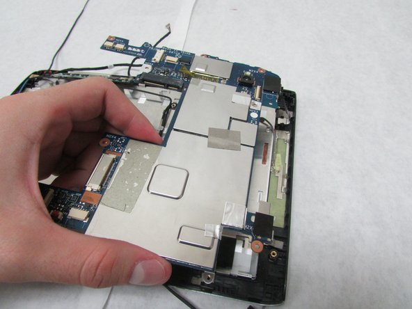
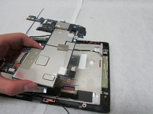
– Grab your trusty Phillips #1 screwdriver and get ready to work some magic! Unscrew those four 4.0 mm Phillips head screws that are keeping the motherboard snug as a bug. You’ve got this!
Tools Used
Step 20
– To put everything back together, just follow these steps in reverse—it’s like rewinding a DIY movie!
– Changed your mind? No worries, you can stop anytime.
– If things get tricky or you need a hand, you can always schedule a repair.
Success!


