How to Replace Nintendo 3DS XL Motherboard: Step-by-Step Guide
Duration: 45 minutes
Steps: 15 Steps
The motherboard should only be replaced as a last resort. Be careful removing it!
Step 1

Make sure your device is totally off before starting. Messing with it while it’s on could give you a shock or fry your gadget.
– Flip the 3DS upside down and take a moment to disconnect anything attached to it—this includes the game card, headphones, charging cable, stylus, or any other accessories. It’s time to give your device some breathing room!
Step 2

The screws are secured with captive washers, so no need to worry about taking them all the way out!
– Grab your trusty JIS #0 screwdriver and gently loosen those two black screws on the back. You’ve got this!

Step 4

– Alright, let’s get that battery out! It’s hanging out on the left side of the 3DS. Just find the little notch up top in the middle and use a non-metal pointed tool to lift it up. Easy peasy!
Step 5

– Grab a JIS #00 screwdriver and carefully remove the six 6mm screws around the edges of the secondary cover.


Step 7

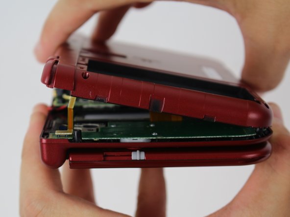

Hold your horses! Don’t yank off the cover just yet, or you might accidentally mess up that fragile ribbon cable still hanging out with the motherboard.
– To separate the cover, carefully lift it up and away from the hinges (in order to clear the headphone port), then pivot it towards the hinges to expose the circuit boards.
Step 8

– Grab a trusty pair of tweezers and gently lift the two plugs that hold the L/R/ZL/ZR button ribbons snugly to the motherboard. Once you’ve done that, you can easily remove the back cover and set it aside like a pro.
Tools Used
Step 9

– Grab your trusty tweezers and gently lift the little hinged flap to unlock the ZIF connector holding the Circle Pad ribbon in place.
– Now, carefully slide the ribbon out of the ZIF connector. Simple, right?
The cable loops over itself and slides into the ZIF connector from the left, but the connector’s locking flap flips up from the right. A common mistake is to tug on the same side as the cable, which could damage the connector. Let’s avoid that and keep things smooth!
To make things a little easier, try unscrewing and removing the Circle Pad first before disconnecting the cable. When it’s time to put everything back, simply reconnect the cable and then slide the Circle Pad back into place. It’s all about making things flow smoothly!
Tools Used
Step 10

– Grab your trusty JIS #000 screwdriver and let’s get to work! Carefully unscrew those two 8 mm screws holding the circle pad in place. You’ve got this!
Step 11

– Gently lift the circle pad casing upward to remove it. You might feel a bit of resistance, but no need to Hulk out on it. It should come off with a firm but gentle touch.
Step 12

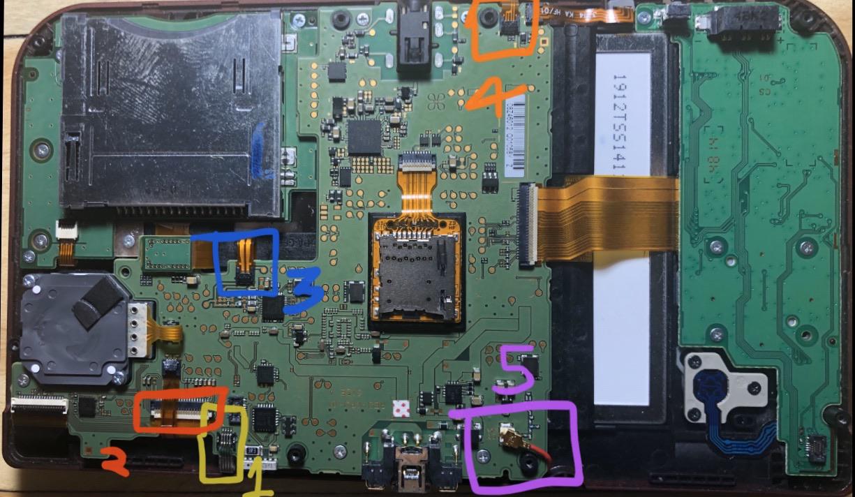
Heads up! Be extra careful not to tug on the red cable.
– Spot the shiny gold terminal plug with the red cable at the top left corner of the motherboard. Gently wiggle and lift it straight up using your fingers to detach.
– Grab a pair of tweezers and pop off the single ribbon connector.
Tools Used
Step 13


These ZIF connectors are held in place by friction, not locks—so, don’t try to lift the flaps like they’re a hinge, or they’ll break!
This connector was once thought to be lock-free, but turns out, most systems have a lock. If you try to remove or reinsert this cable without unlocking it, you’ll damage the cable and might need a new Touch Screen digitizer. Luckily, the LCD is connected with other ZIFs, so no worries there.
If you’re working on a system where this connector doesn’t have a lock, no need to force the flap up! It should pop up easily. If it doesn’t, it probably just uses friction to hold the cable in place, so try gently pulling the cable out of the connector.
The SD card reader in this pic is shown as taken out, but don’t worry, it’s not a must for getting that motherboard out.
– Grab your trusty tweezers and gently coax those four highlighted ribbons out of the ZIF connectors on the motherboard’s sides. You’ve got this!
– Three of those ribbon connectors come with handy plastic clamping flaps to keep things snug. Just flip them up with your tweezers before you pull the ribbons out.
– Now, there’s this one ribbon connector that has a flap too, but it’s a bit different—think of it like the one for the Circle Pad. Just gently lift the flap on the side opposite the ribbon cable to free it.
– When it’s time to put everything back together, don’t forget to snap those ZIF clamps back down. You’re almost there!
Tools Used
Step 14

– Time to get started! Use a JIS #000 screwdriver to carefully remove six 4mm screws from the edges of the motherboard. Easy peasy!
Step 15


Pay attention to the direction the ribbons slide into their connectors, since they can be pretty particular.
– Gently rotate the motherboard 90 degrees towards the hinges. This will reveal two more ZIF connectors on the motherboard’s underside.
– Both have latches that need flipping up. The left one is longer and black; the right one is shorter and white. Flip up the flaps, slide out the ribbons, and remove the motherboard.
Success!