Xbox One Heat Sink Replacement Guide
Duration: 45 minutes
Steps: 8 Steps
Inside the Kinect, you’ll find the heat sink assembly – it’s like the backbone of this device. A bunch of important components are attached to it, including the colour camera, IR camera, and IR blasters. Let’s take a closer look.
Step 1

– First, let’s get started by removing the sticker on the underside of your device – it’s time to uncover what’s underneath!
– Next, grab your trusty screwdriver and remove the four 3.1×23.5 mm T10 screws that are hiding underneath the sticker. Easy does it!
– While you’re in the zone, go ahead and remove the four 3.1×7.5 mm T10 screws that are also beneath the sticker. Take note of their sizes and locations, so you can put everything back together smoothly later on.
Step 2


– Let’s get started by taking off the back panel. It’s like opening a present, but way cooler!
– Next up, gently remove the black panels on either side of the Kinect. Underneath, you’ll find those sneaky 3.1×7.5mm T10 screws waiting for you. Time to unscrew them and keep moving forward!
Step 3


– Give the outer case a good press on both sides with your thumbs. This will pop the internal assembly loose.
– Use the spudger to lift the internal assembly out.
– Take the assembly out of the case. Now, you’re looking at the inner shell of the kinect, the heat sink, microphone, and LED sensor.
Tools Used

Step 4

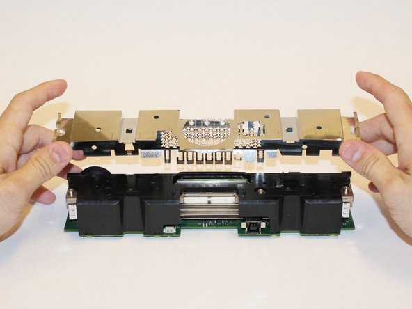
– Let’s get started by removing the eight 2.9×7.6 mm T9 screws from the rear of the internal case – this will give you access to the inside.
– Next, carefully lift the internal metal case away from the plastic shell that houses the heat sink assembly. Take your time and make sure it’s fully detached.
Step 5


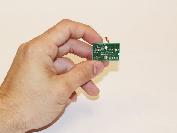
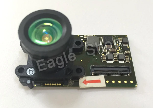
– Pop off that ribbon cable connecting the sensor driver board to the motherboard.
– Unscrew the 3.0×7.5 mm T9 screw that’s securing the sensor driver board to the heat sink.
– Gently lift out the infrared sensor board for the Kinect.
Step 6


– Gently wiggle out the ribbon cable that connects to the microphone using your trusty tweezers.
– Unscrew those four T9 screws (3.1×7.7 mm) that are holding the microphone snugly against the heat sink assembly.
– Time to say goodbye to the stand—remove it with care!
Tools Used

Step 7
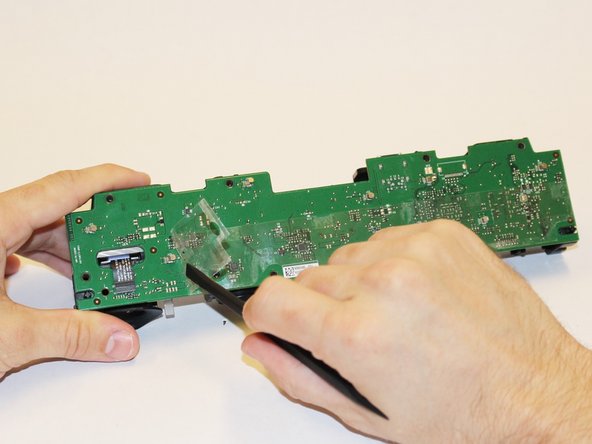
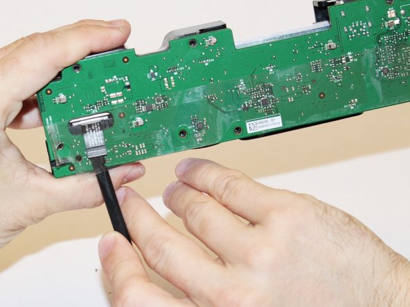

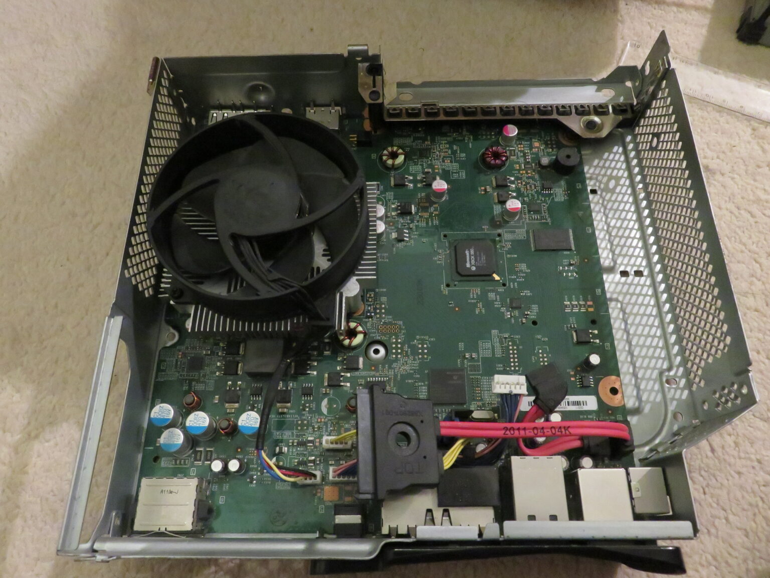
– Let’s kick things off by removing those eight T9 screws that are holding the motherboard in place. They’re 3.0×7.6 mm in size, so grab your bit and get to it!
– Now, gently peel away that plastic film from the motherboard using your trusty spudger. It’s like unwrapping a present!
– Lastly, carefully disconnect the ribbon cable for the color camera using the spudger. Keep it steady, and don’t worry, you got this!
Tools Used
Step 8


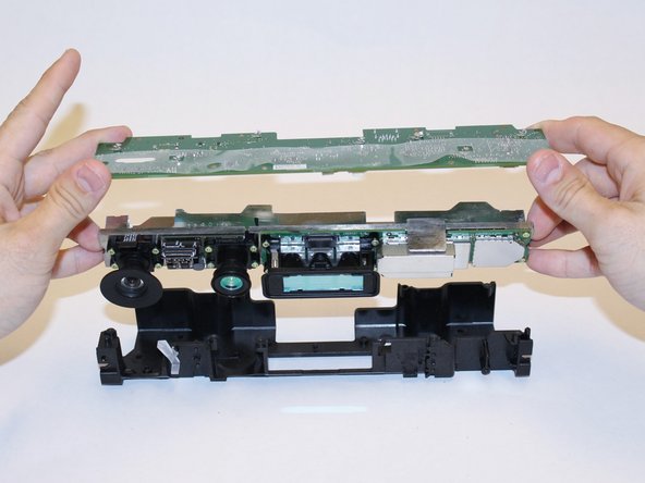
– Gently lift the motherboard along with the heat sink assembly out of the plastic shell. Now you’ve got a front-row seat to all the components attached to that heat sink!