Replace Google Pixel 9 Pro Fold Rear Camera: DIY Guide
Duration: 45 minutes
Steps: 110 Steps
This repair guide was crafted with care by our team, and while it hasn’t been given the thumbs up by any tech giants, it’s packed with all the know-how you need. Dive into our repair guides and let’s get fixing!
This handy guide is here to help you swap out the rear camera assembly in your Pixel 9 Pro Fold. It’s crafted with care by the team at Salvation Repair. For more details on our repair guides, check it out here. If you find yourself in a pinch, remember, you can always schedule a repair!
Step 1

– First things first, unplug all the cables from your phone and give it a complete power down. We want to make sure everything is safe and sound before we get started.
Step 2


If your back cover is super cracked, you can try sticking a clear packing tape over it to give the suction cup a better grip. Or, use some really strong tape instead of the suction cup! And if those ideas don’t work, you can always superglue the suction cup to the back cover. No worries, it happens.
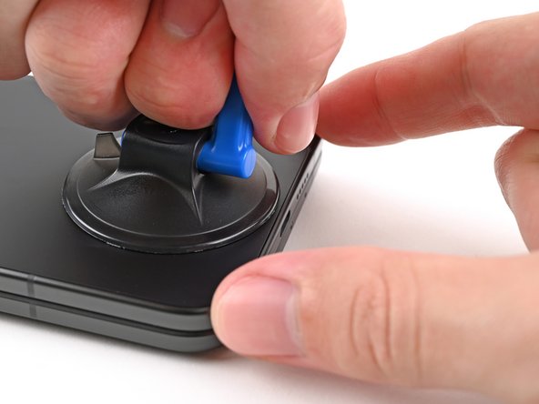
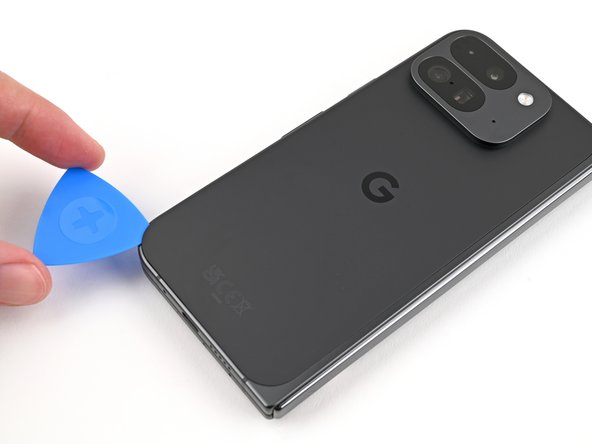
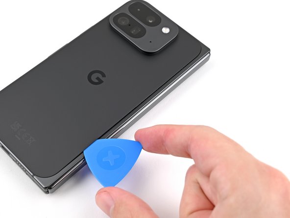
– Stick a suction cup right onto the back cover, aiming for the center of the bottom edge. Make sure it’s nice and snug.
– Hold the phone steady with one hand, and use your other hand to pull up on that suction cup. Give it a good, strong tug to create a little gap between the back cover and the frame.
– Slide an opening pick into the gap. You’re getting closer!
Step 3

Okay, so for the next two steps, be a little careful with the opening pick! Don’t go digging deeper than 3 mm, or you might get a little too friendly with the metal springs around the frame. No worries, though, we’re here to help. Just take it slow and steady.
For an extra boost in your repair game, feel free to measure and mark your opening pick at 3 mm. It’ll give you a handy visual reference for the length. Keep it fun and let’s get to it!
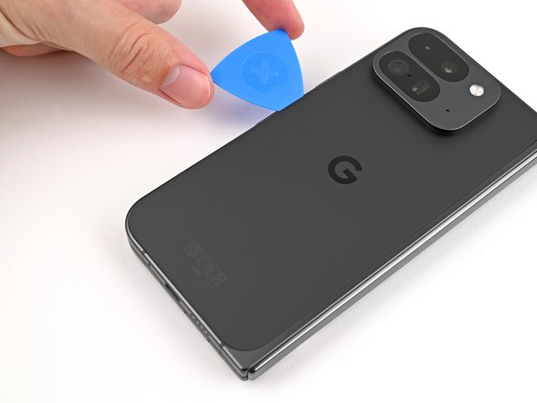
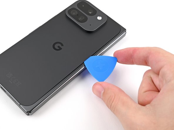
– Gently detach the suction handle from the back cover, like peeling off a sticker.
– Carefully slide the opening pick around the bottom left corner and up the left edge of the back cover to break the adhesive seal. You’re doing great!
Tools Used

Step 4

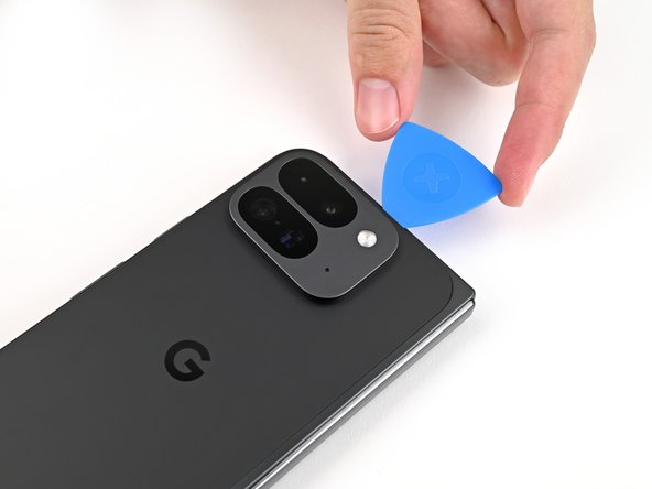
– Keep gliding that pick around the top left corner and along the top edge of the back cover like a pro!
Step 5

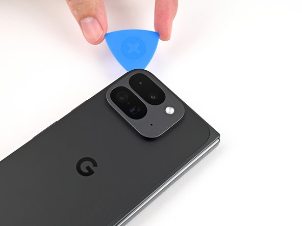
The adhesive on the right edge of the back cover is a bit of a thickie compared to the rest. Make sure to slide your opening pick in at least 4 mm to break that stickiness free.
– Gently glide your pick along the right edge and around that tricky bottom right corner to break free any stubborn adhesive still holding on.
Step 6

Hold up there, partner! The back cover is still attached by a cable. Let’s keep it connected for now, okay?
Now you should see the back cover is loose from the frame. If it’s still a bit sticky around the edges, a helpful opening pick can help dislodge any leftover adhesive. You’re doing great! Almost there!
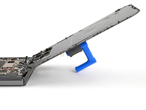
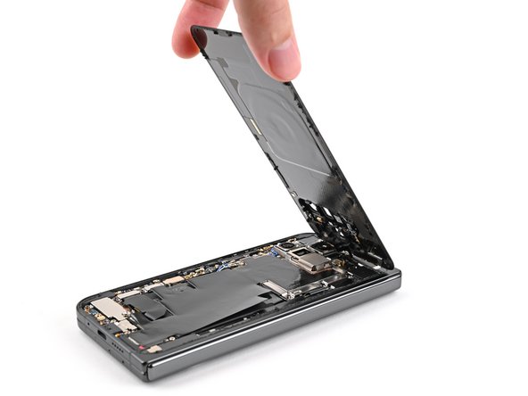
– Gently lift the bottom edge of the back cover and swing it over the top edge of your phone like a pro.
– Support the back cover with your trusty suction handle or a clean, sturdy object—just be sure that the cable is comfy and not under any stress.
Tools Used
Step 7

As you dive into this repair adventure, be sure to keep track of every little screw! They all have their special homes, and you’ll want to return them just where they belong.
The Pixel 9 Pro Fold has those nifty Torx Plus screws, but don’t fret! Standard Torx bits can join the party too. Just grab a T3 or T4 Torx bit and remember to apply steady, downward pressure to avoid stripping those threads. You’ve got this!
– Grab your Torx Plus 3IP driver and unscrew that 3.0 mm-long screw holding the top bracket in place. Easy peasy!
Step 8

– Whoa there, adventurer! Time to unleash the tweezers’ mighty grip or your super duper fingers to give that top bracket a gentle tug-n-release, all the way to the top of the phone. Once it’s loose, wave goodbye to that top bracket, and enjoy the feeling of making progress on this fun repair journey!
Step 9

Keep your spudger in its designated spot! Wandering off with it could lead to some unexpected surface-mounted component gymnastics, and we definitely don’t want that.
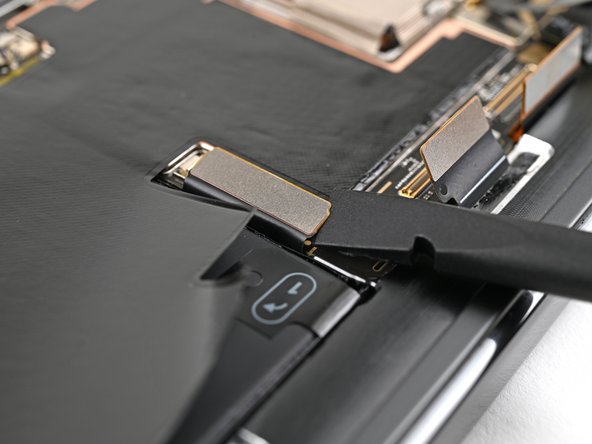
– Slide your spudger’s tip gently under the edge of the back cover cable connector—no rush, you’ve got this!
– Carefully lift and pop the back cover cable free. Easy peasy!
Tools Used


Step 11

– Grab your trusty Torx Plus 3IP driver and get ready to tackle those two 3.0 mm-long screws holding down the base battery bracket. You’ve got this!

Step 13

Keep your spudger in its designated spot! Straying from the path could send those tiny surface-mounted components flying.
– Slide the tip of your trusty spudger under the bottom left corner of the base battery press connector, right by that little gold marker. You’ve got this!
– Gently pry upwards to disconnect the base battery. Nice work—you’re making progress!
Tools Used
Step 14

– Grab your trusty spudger and gently wiggle it to lift up and disconnect the USB-C port board cable press connector. You’re doing great!
Tools Used
Step 15

– Grab your trusty Torx Plus 3IP driver and pop out those two 3.0 mm long screws holding the vibrator bracket in place. You’ve got this!

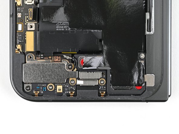
Step 17

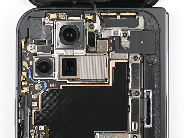
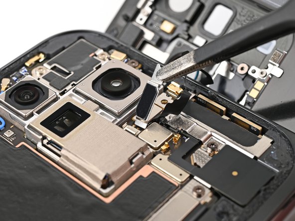
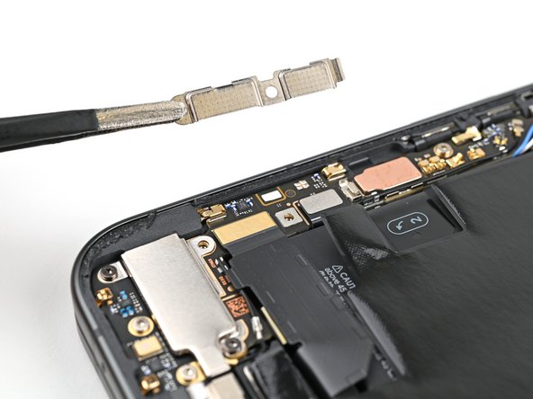
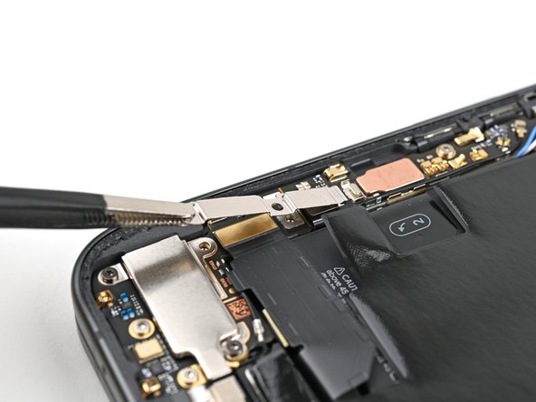
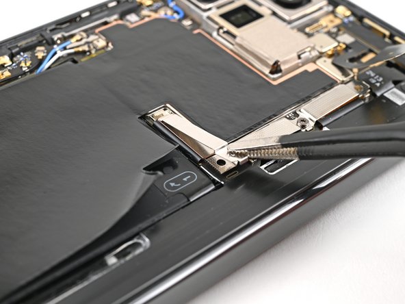
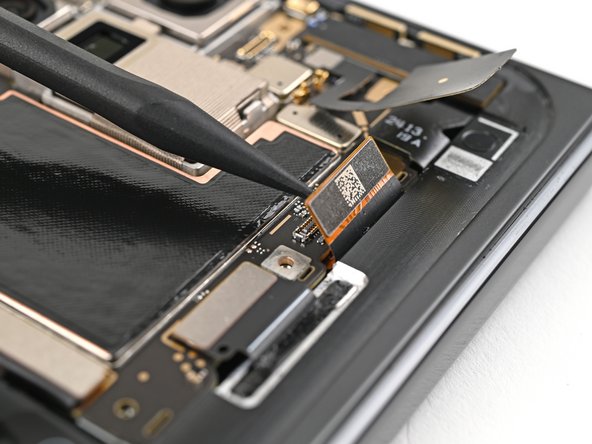
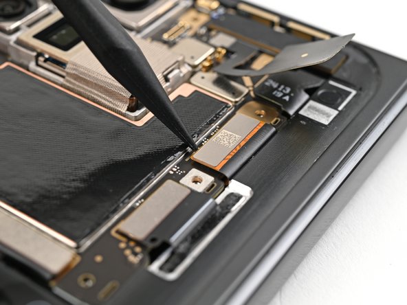
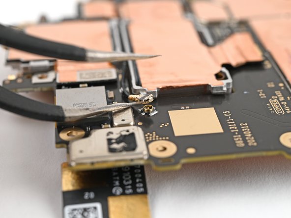
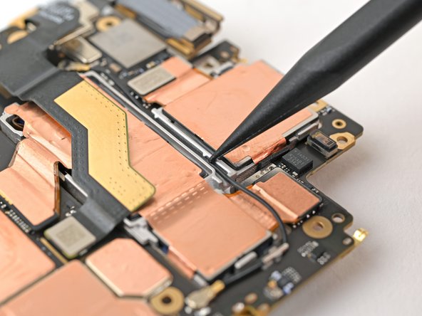
– Gently slide one arm of your trusty angled tweezers beneath the metal neck of the black antenna cable’s connector head on the USB‑C board.
– Now, with a steady hand, lift straight up to disconnect the cable.
Tools Used

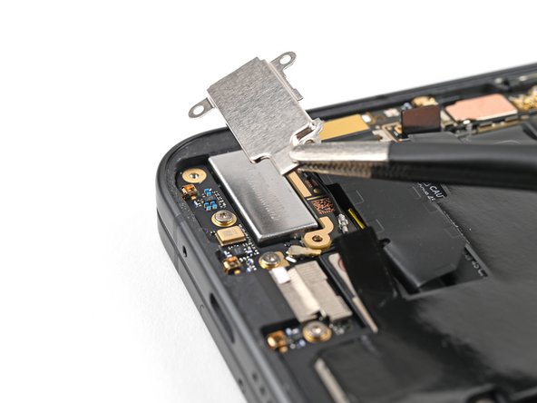
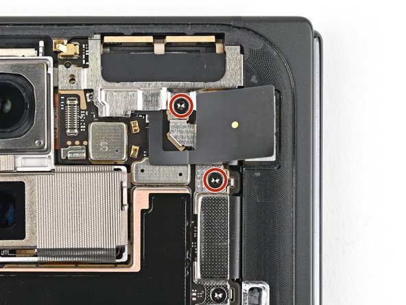
Step 18

– Grab your Torx Plus 3IP driver and unscrew the two 2.6 mm-long screws holding the inner front camera bracket in place. Easy peasy!
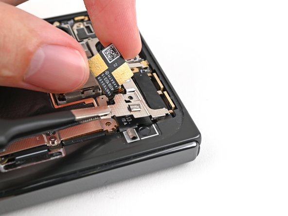
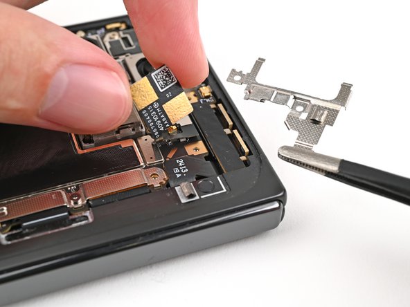
Step 19

– Grab those tweezers or use your fingers to gently lift the inner front camera bracket up and towards the left edge of the phone. This will help you pop those clips loose!
– Now, go ahead and remove the inner front camera bracket. You’re doing great!
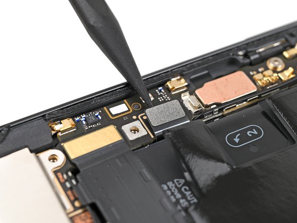
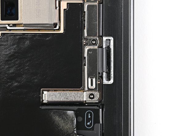
Step 20

– Grab your trusty spudger and gently pry up that inner front camera press connector. It’s like giving it a little nudge to say ‘see ya later!’
Tools Used
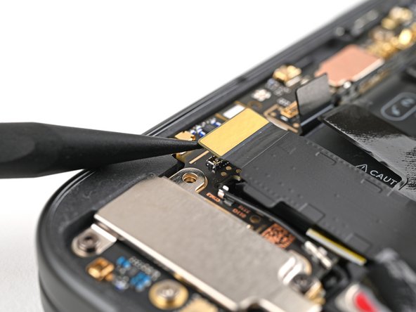
Step 21

– Time to give that inner front camera a little nudge! Gently pry it up from the frame using the tip of your spudger, carefully separating the adhesive holding it in place.
– Now, gently remove the inner front camera. You’re doing great!
Tools Used
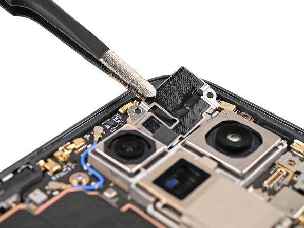
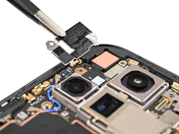
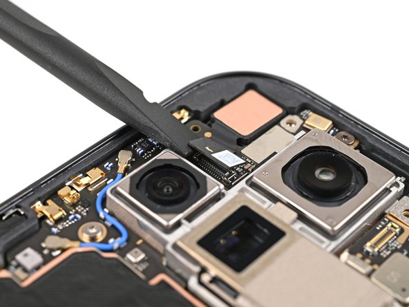
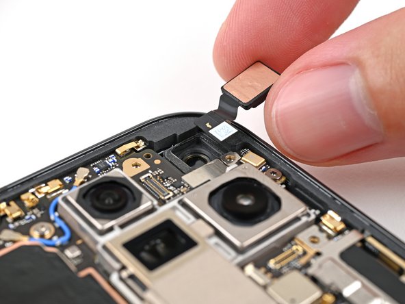
Step 22

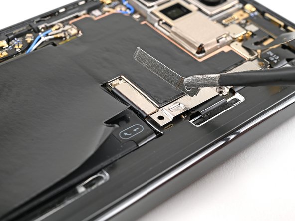
– Gently slide the flat end of your trusty spudger under the ultra wideband antenna to break free the adhesive foam that’s holding it snugly to the frame.
– Now, grab your tweezers or just your fingers to carefully lift the antenna off the frame. This will help you detach any lingering adhesive that’s still trying to keep them together.
Tools Used
Step 23
– Grab your trusty Torx Plus 3IP driver and get ready for action! It’s time to unscrew those two 3.0 mm-long screws that are holding the ultra wideband bracket in place. You’re on your way to a successful repair!
Step 24

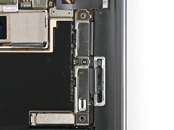
– Gently hold that ultra wideband antenna to the side and give the bracket a little tug towards the bottom of the phone to pop those clips loose. You’ve got this!
– Now, go ahead and take out the ultra wideband bracket.
Step 25

– Grab your Torx Plus 3IP driver and unscrew the 3.0 mm-long screw holding the interconnect cable bracket in place. Easy peasy! If you need help, you can always schedule a repair.
Step 26

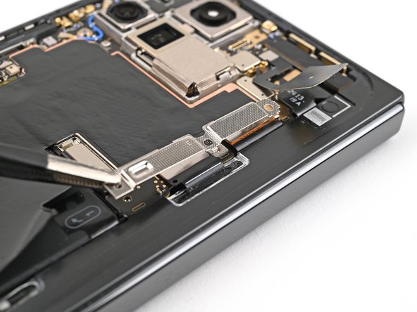
– Grab your trusty tweezers or just use your fingers to gently nudge the bracket towards the right edge of the phone. This will help you pop that clip loose like a pro!
– Now, it’s time to remove the bottom interconnect cable bracket. You’re doing great!
Step 27

– Alright, champ! Grab that Torx Plus 3IP driver and give that little 3.0 mm screw holding the inner display cable bracket a friendly farewell. You got this!

Step 29

Easy peasy, no need to go spazzy, just avoid poking that super duper small gizmo on the surface!
– Let’s disconnect that inner display cable! Grab your trusty spudger and gently slide its tip under the bottom left corner of the inner display press connector. You’ll spot a gold marker on the logic board – that’s your target area.
– Now, with a smooth, careful motion, pry up the inner display cable. You’ve got this!
Tools Used
Step 30
– Give it another go! Disconnect those top and bottom interconnect cable press connectors just like before, and remember to gently pry next to those shiny gold markers. You’re doing great!
Step 31

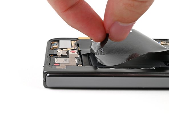
– Gently peel off the graphite sheet from the bottom speaker to release the adhesive holding it in place.
Step 32
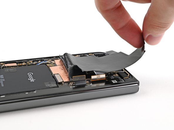

– Now, let’s get this graphite sheet off the logic board! Keep peeling it back, separating the adhesive bit by bit. You’ve got this!
Step 33

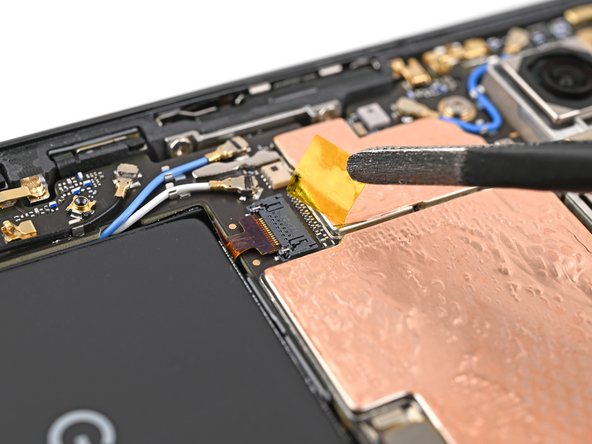
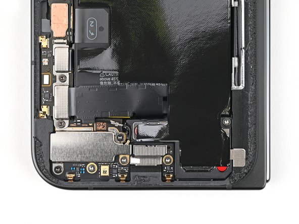
– Grab your trusty tweezers or your nimble fingers and gently peel away the yellow tape from the side button cable ZIF connector. You’re doing great!
– Once you’ve got that tape off, set it aside for now. It’ll come in handy when it’s time to put everything back together.

Step 35

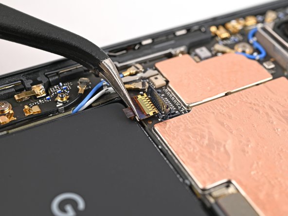
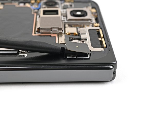
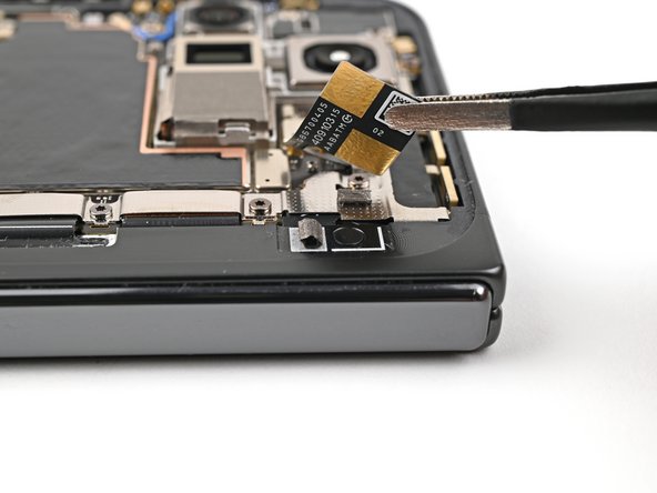
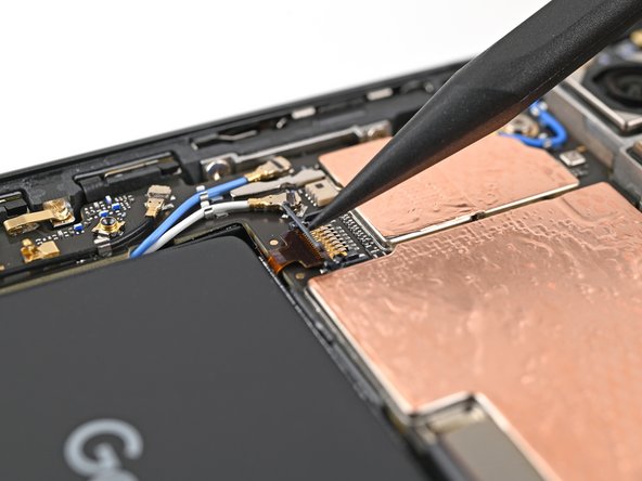
Be super careful with the battery—poking it could lead to leaks or even a fiery surprise! If you need help, you can always schedule a repair.
– Take those trusty angled tweezers and gently nudge the side button cable right out of its cozy little slot. You’re doing great!
Tools Used
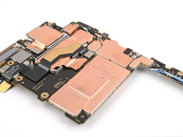
Step 36

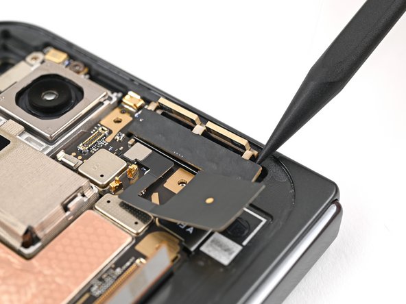
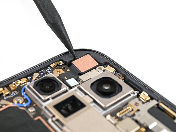
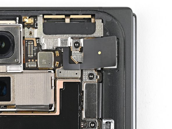
A thermal pad gives just a gentle nudge to the 5G mmWave antenna, keeping it cozily connected to the frame.
– Gently slide the spudger’s tip under the 5G mmWave antenna and lift it away from the frame, separating it from the thermal pad below. Take it slow and make sure everything stays intact—you’ve got this!
Tools Used
Step 37

– Grab your trusty Torx Plus 3IP driver and let’s tackle those screws holding the logic board in place:
– One sneaky little 2.2 mm-long screw
– Two slightly longer 2.6 mm-long screws, ready to be unscrewed!
Step 38

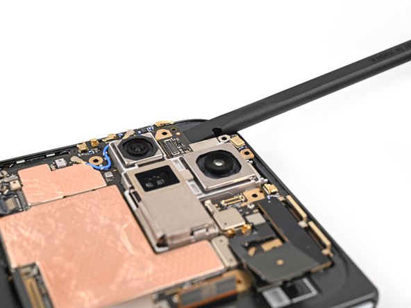
You might notice a bit of a tug since the logic board is glued to the frame with thermal paste. Just give it a little love and it should come free!
– Gently slide the flat end of your trusty spudger under the top left corner of the logic board, right next to the inner front camera cutout. You’re doing great!
– Now, lift the logic board just enough so you can get a good grip on the top edge with your fingers. You’ve got this!
Tools Used
Step 39
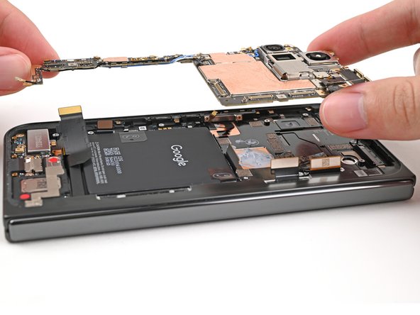
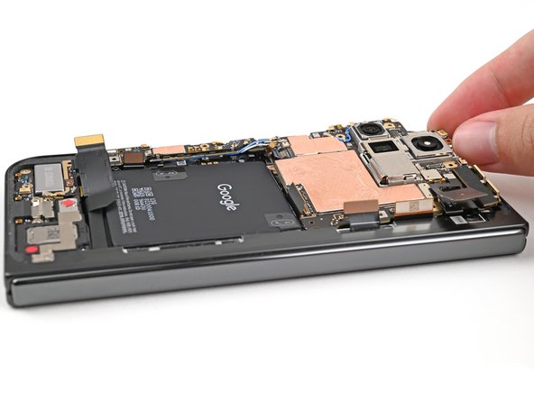
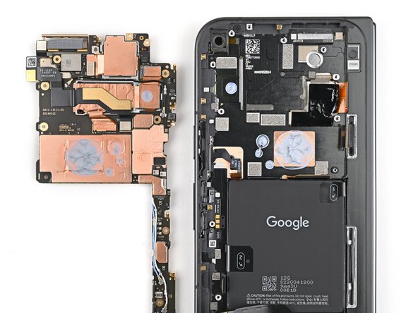
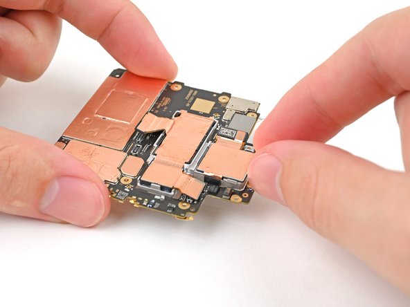
– Gently lift the top of the logic board away from the frame and set it free.
– Carefully flip the logic board over and place it on a clean surface, ready for its next adventure.
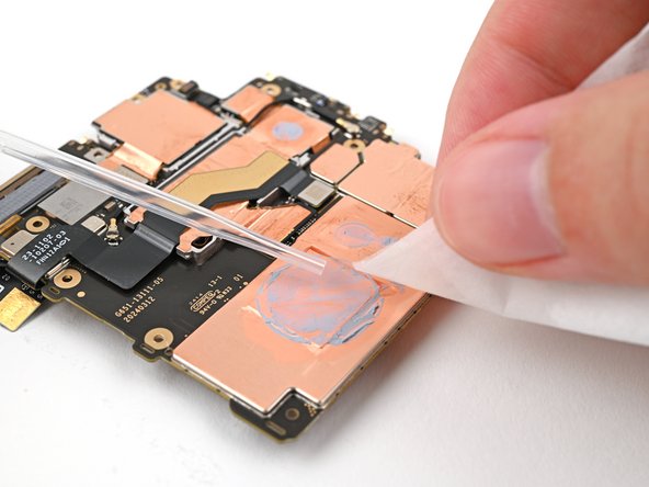
Step 40
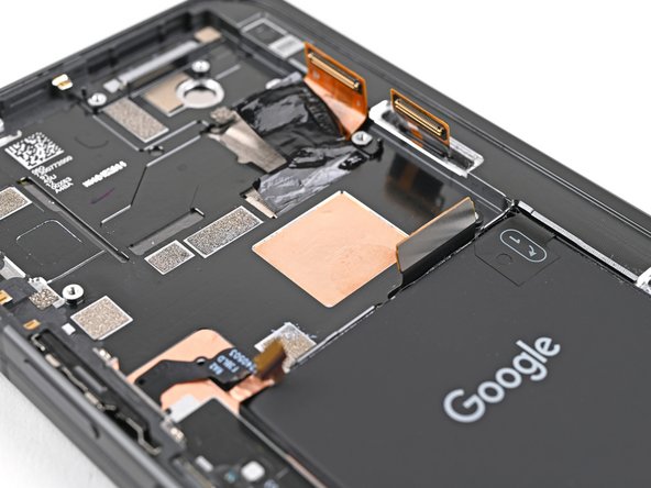
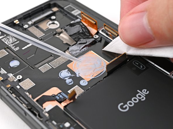

– Grab that handy spudger and gently scrape off any big chunks of old thermal paste that are hanging out on the frame.
– Now, let’s get those last bits of thermal paste out with a little help from some high-strength isopropyl alcohol (90% or more). Just a couple of drops will do the trick.
– Take a clean coffee filter or lint-free cloth and wipe away any remaining residue. We’re getting close to a fresh start!
Tools Used
Step 41

Be gentle with the logic board while giving it a clean! Pressing too hard can bend those little metal springs or leave smudges on the rear camera assembly. Keep it light and breezy!
– Give the thermal paste cleaning action another go on the underside of the logic board!

Step 43

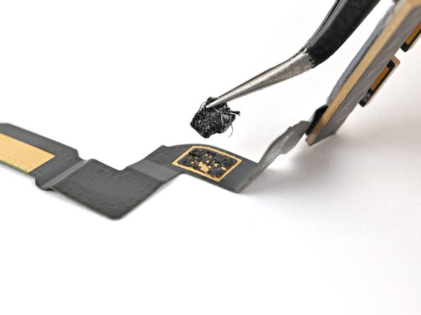
The 5G mmWave antenna cable is held in place by adhesive on both sides of the logic board. It’s like a cozy hug for your cable, keeping it snug and secure!
– Gently slide the flat end of a spudger under the section of the 5G mmWave antenna cable that’s stuck to the bottom of the logic board.
– Give the cable a little nudge to break free from its adhesive grip.
– Using tweezers or your fingers, carefully pull the cable away from the logic board, making sure to detach any leftover adhesive.
Tools Used
Step 44

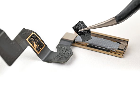
– Time to rock and roll! Let’s repeat the last step for that 5G mmWave antenna cable stuck to the top of the logic board.
– Now, it’s time to give that 5G mmWave antenna its freedom. Let’s gently remove it.
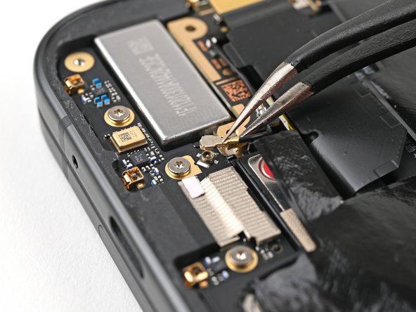
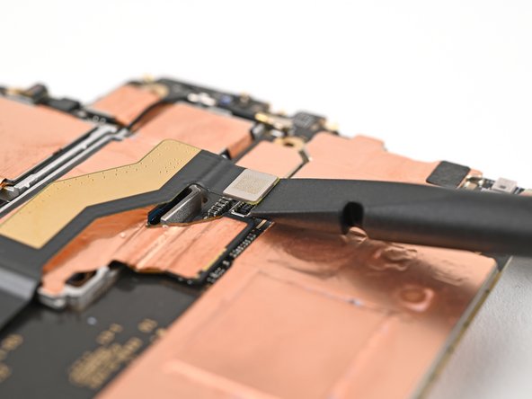
Step 45

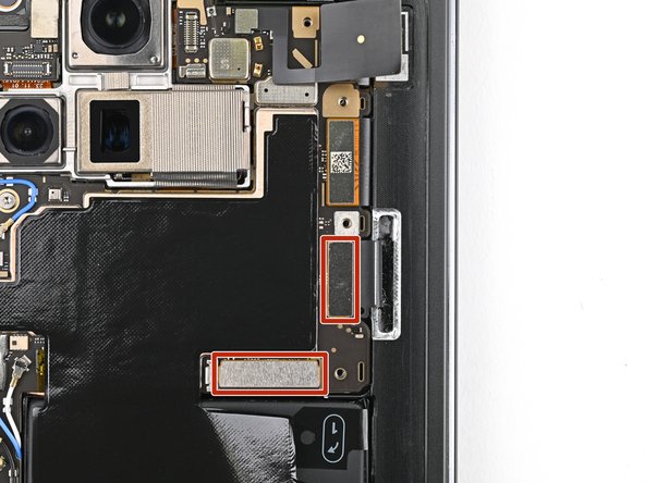
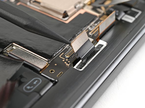
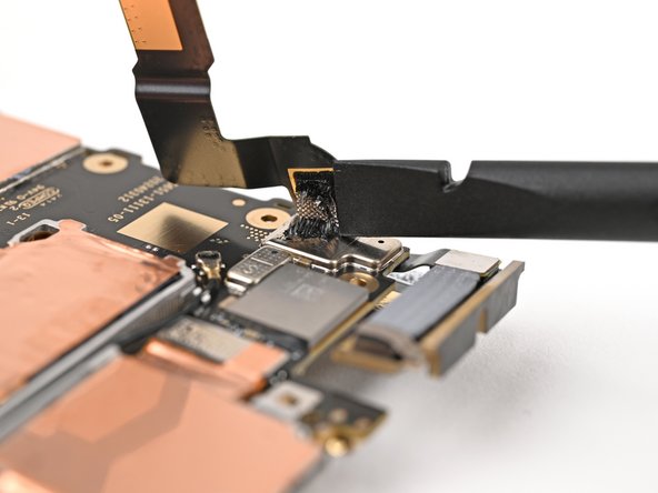
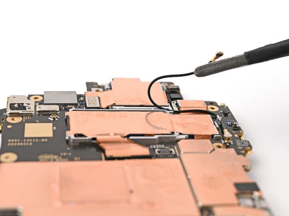
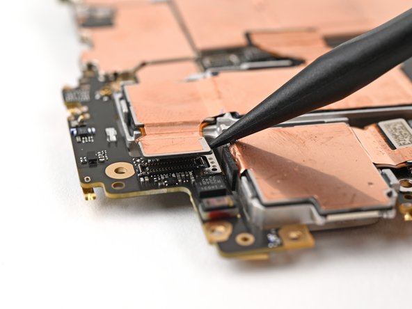
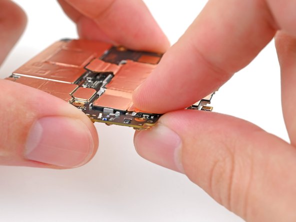
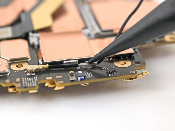
– Gently slip one arm of your trusty angled tweezers beneath the metal neck of the rear camera antenna cable’s connector head.
– Now, give it a little lift straight up to disconnect the cable. Easy peasy!
– Repeat this graceful move for the other connector head. You’ve got this!
Tools Used
Step 46

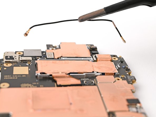
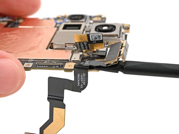
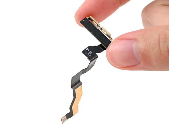
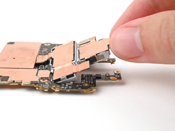
– Grab your trusty tweezers or just use your fingers to gently lift the antenna cable out of its cozy little groove on the rear camera assembly.
– Now, it’s time to say goodbye to the antenna cable and remove it with care.

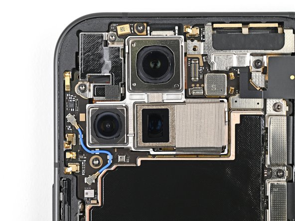
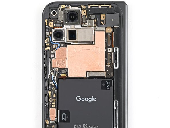
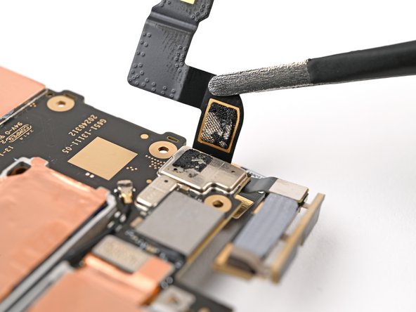
Step 48

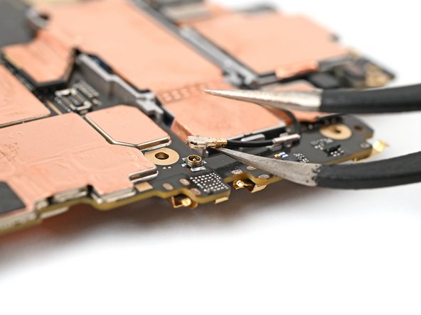
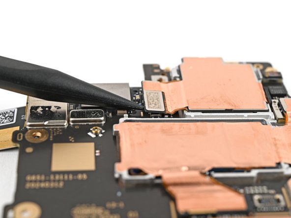
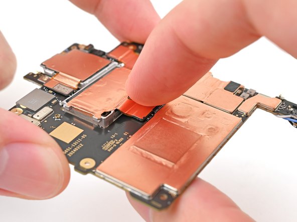
The ultrawide camera press connector is missing that shiny gold marker we often look for. No worries! Just slide that spudger right under the elevated silver platform beside the wide camera, and you’re on your way to success!
– Give those ultrawide and telephoto camera press connectors some love by repeating the previous step!
Tools Used
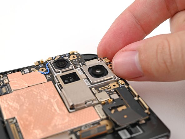
Step 49
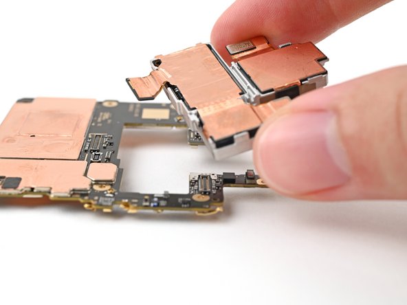

– Gently lift the rear camera assembly out of its cozy spot on the logic board and set it free.
Step 50

– Awesome job on getting through the disassembly! Now, let’s dive into the fun part—putting your device back together. Follow these steps, and you’ll have it up and running in no time!
Step 51
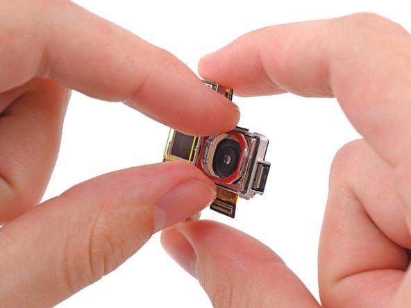

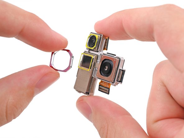
Your shiny new front camera assembly might come with some lightweight plastic covers snugly stuck on each lens. If yours doesn’t have those, feel free to skip this step!
– Gently use your fingers to pop off those three lens covers from your shiny new rear camera assembly!
Step 52

– Carefully line up your shiny new rear camera assembly and gently set it into its cozy spot on the logic board.
Step 53

Avoid the temptation to jam that connector in there! If it’s being stubborn, just give it a little nudge and try again. You’ve got this!
– Gently line up one of the rear camera assembly’s press connectors right above its socket, then give it a little nudge with your fingertip until you hear that satisfying click!
Step 54

– Feel the satisfaction as you double up on that fun by repeating the previous step for the other two rear camera press connectors. That’s right, you’re on a roll! Keep going!
Step 55

– Grab those tweezers and hold one of the rear camera assembly’s antenna connectors right over its socket. Give it a gentle press with your finger or a spudger until you hear that satisfying snap!
– Now, let’s do the same for the other connector on the antenna cable. You’ve got this!
– Take your spudger or your trusty fingers and press the antenna cable snugly into its clips and groove in the rear camera assembly.
Tools Used
Step 56