DIY Guide: Google Pixel 9 Pro Fold Logic Board Replacement
Duration: 45 minutes
Steps: 91 Steps
This repair guide was created by the talented team at Salvation Repair and is not officially sanctioned by any other entity. If you want to dive deeper into our repair guides, feel free to check them out right here!
This nifty repair guide is crafted for you to help replace the logic board in your Pixel 9 Pro Fold. While we love sharing our knowledge, this guide isn’t officially associated with any big names. Ready to dive in? If you hit a snag, don’t hesitate to schedule a repair!
Step 1

– First things first, unplug all those cables from your phone and give it a nice, cozy shutdown. It’s like tucking it in for a little nap!
Step 2
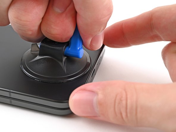


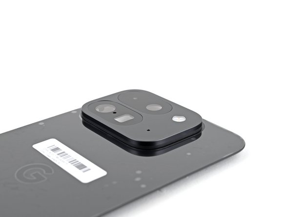
If your back cover is looking a bit worse for wear with some serious cracks, don’t sweat it! Slap on a layer of clear packing tape to give that suction cup a fighting chance to stick. If you’re feeling adventurous, you can use some really strong tape instead of the suction cup. And if you’re still having no luck, a little superglue can work wonders to attach the suction cup right onto the cracked back cover. You’ve got this!
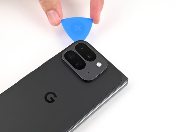
– Stick that suction cup right on the back cover, aiming for the sweet spot near the bottom edge.
– Hold your phone steady with one hand, and give that suction cup a confident, smooth tug to pop a little space between the back cover and the frame.
– Slide your opening pick into the gap you just created—nice and easy!
Step 3

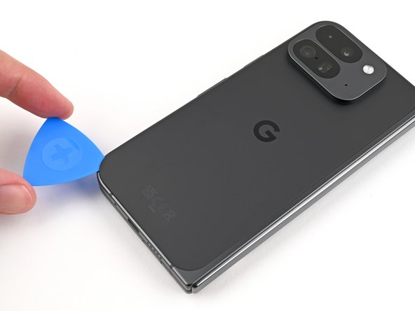
As you tackle the next couple of steps, remember to keep your opening pick within the friendly limit of 3 mm! Going deeper might tick off those metal springs around the frame, and we definitely don’t want that!
If you’re feeling fancy, grab a ruler and mark your opening pick at 3 mm. It’ll help give you a better idea of the length you’re working with!
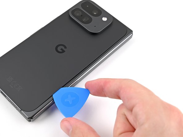
– Gently peel off the suction handle from the back cover, like you’re giving it a little hug goodbye.
– Take that trusty opening pick and slide it around the bottom left corner, then up the left edge of the back cover to break free the adhesive’s grip. You’ve got this!
Tools Used

Step 4

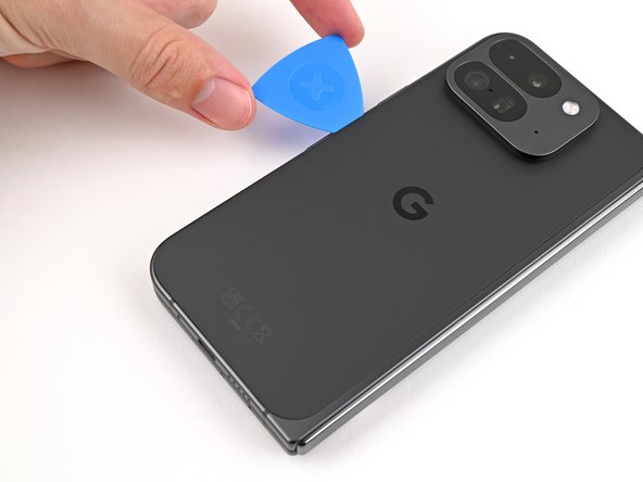
– Keep that pick gliding around the top left corner and smoothly across the top edge of the back cover. You’re doing great!
Step 5
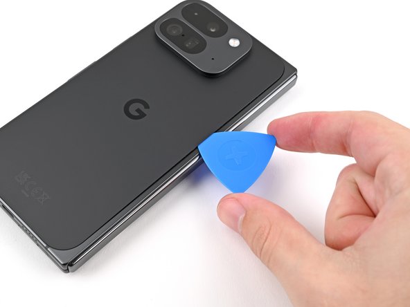

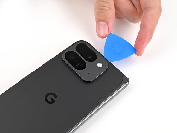
Alright, so the adhesive along the right edge of the back cover is a bit thicker than the rest. Just keep that in mind and make sure to insert your opening pick at least 4mm in to make sure you get things separated properly. You got this!
– Gently glide your pick along the right edge and around the bottom right corner to free up the last bits of adhesive. You’ve got this!
Step 6
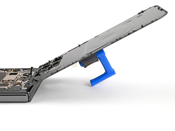

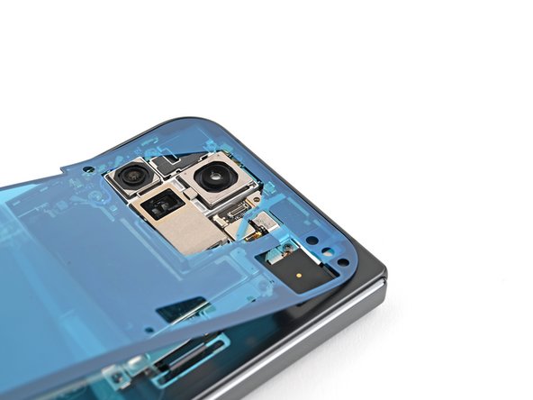
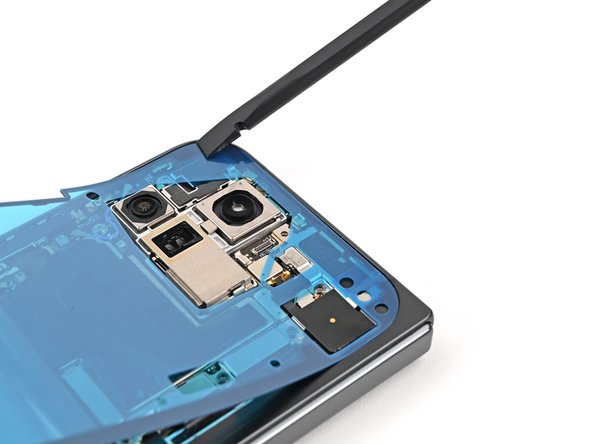
Hold up! The back cover is still attached by a cable, so don’t yank it off just yet.
At this stage, the back cover should be happily detached from the frame. If you’re still feeling some stubbornness around the edges, grab an opening pick and gently coax apart any lingering adhesive. You’ve got this!
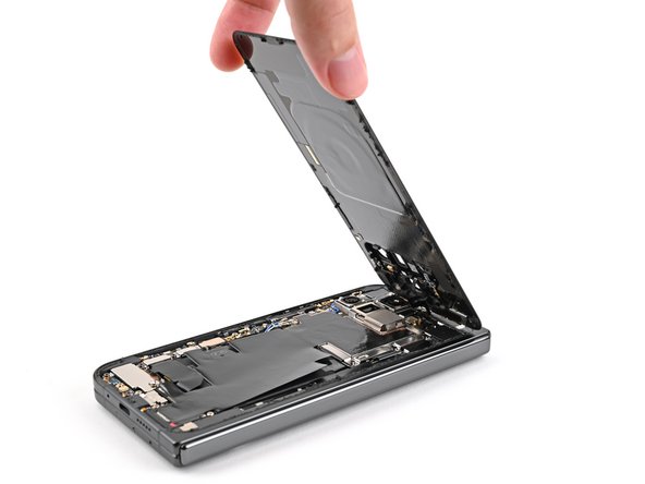
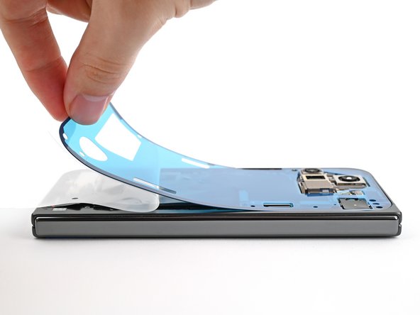
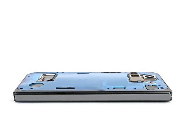
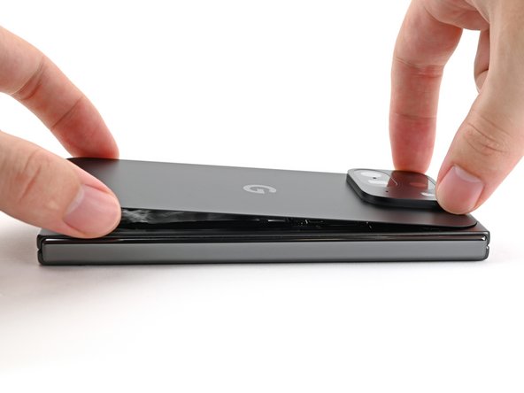
– Alrighty then, let’s give it a little heave-ho and lift that bottom edge of the back cover. Now, give it a little spin and swing it over to the top edge. It’s like a magic trick, you’ve got to see it to believe it!
– Now, let’s prop this fella up with your trusty suction handle or a nice, sturdy object there. Make sure that cable stays comfy and doesn’t look all strangled and uncomfortable, alright? Y’know, it’s all about cable comfort!
Tools Used
Step 7

Alright, let’s keep things organized! Make sure you put each screw back where it came from. Think of it like a puzzle – we don’t want any missing pieces!
No worries if you see a Torx Plus screw! Standard Torx bits will work just fine. Just use the same size or go up one size – a T3 or T4 Torx bit should do the trick! Just remember to apply steady pressure when you’re screwing things in to prevent stripping. You got this!
– Grab your trusty Torx Plus 3IP driver and give that 3.0 mm-long screw holding the top bracket a little spin to the left. You got this!
Step 8

– Grab your tweezers or use your fingers to gently tug the top bracket upwards, freeing it from its clip.
– Now, go ahead and remove that top bracket. You’re doing great!
Step 9

Careful with that spudger! Keep it to the specified areas, or you might end up moving some delicate components around.
– Sneak your spudger’s tip under the bottom edge of the back cover cable press connector.
– Lift and unplug the back cover cable with a smooth move.
Tools Used


Step 11

– Grab your Torx Plus 3IP driver and unscrew the two 3.0 mm-long screws holding the base battery bracket in place. Easy peasy!

Step 13

Keep your spudger in its designated zone! Wandering off could cause some surface-mounted components to take a vacation.
– First, let’s shine some light and have a peep under the hood (where the ‘spirit’ lives). Locate that base battery press connector and follow its shiny gold marker. Then, with your trusty spudger, gently pry up that sucker and disconnect! Give that bad boy some breathing room – well, not the bad boy, the battery connector. You know what they say: when in doubt, make a spark!
Tools Used
Step 14

– Grab your trusty spudger and gently lift up the USB-C port board cable connector. It’s a simple move to disconnect it, so go ahead and give it a go!
Tools Used
Step 15


– Grab your trusty Torx Plus 3IP driver and let’s get to work! Carefully unscrew those two 3.0 mm-long screws holding the vibrator bracket in place. You’ve got this!

Step 17

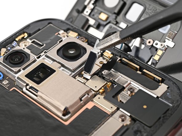
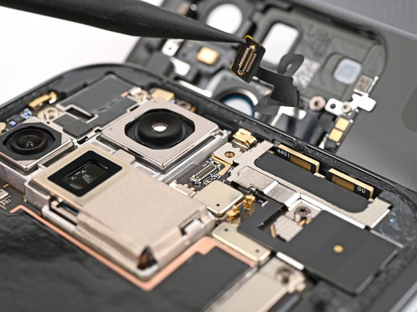
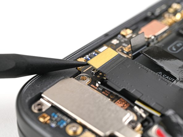
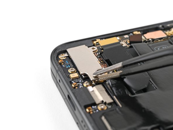
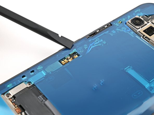
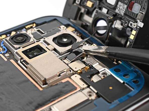
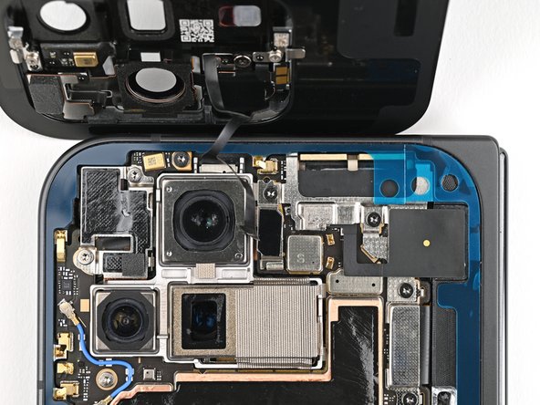
– Here’s an antenna maneuver: grab your angled tweezers, pick up one end of the black cable connector on the USB-C board.
– With confident flair, lift it straight up to disconnect the cable.
Tools Used

Step 18

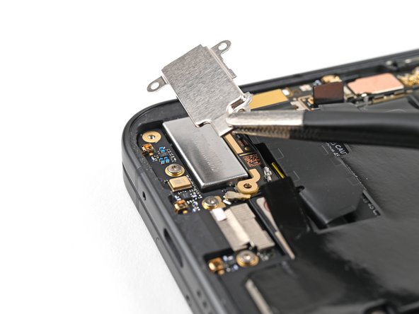
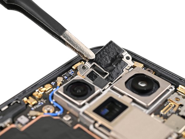
– Alright, time to take out those screws holding the inner front camera bracket in place! Grab your trusty Torx Plus 3IP driver and give those two little 2.6mm screws a spin.
Step 19


– Grab those handy tweezers, or use your fingers if you’re feeling daring, and gently lift the inner front camera bracket up towards the left side of the phone to pop those clips free.
– Now, go ahead and remove the inner front camera bracket with care!
Step 20

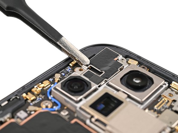
– Feeling adventurous? Use a spudger to play superhero and disconnect the inner front camera press connector!
Tools Used
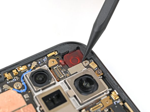
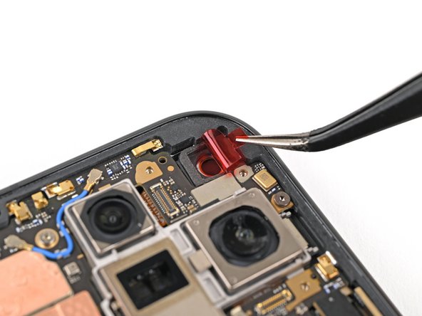
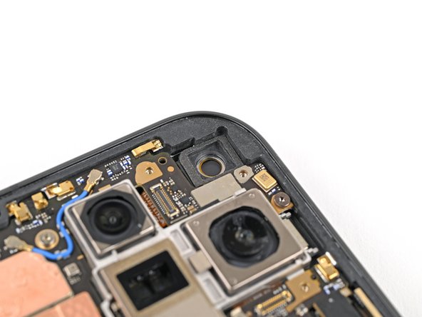
Step 21

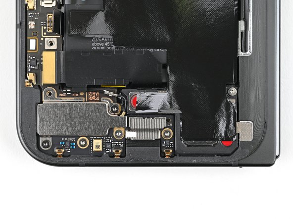
– Grab your trusty spudger and cleverly slide the point underneath the inner front camera. Give it a gentle nudge to break free the adhesive that’s keeping it stuck to the frame.
– Once you’ve got it free, go ahead and pop out the inner front camera!
Tools Used

Step 23
– Grab your trusty Torx Plus 3IP driver and let’s get those two 3.0 mm screws out of the ultra wideband bracket. You’ve got this!
Step 24

– While gently keeping the ultra wideband antenna out of the way, give the bracket a little tug toward the bottom of the phone to pop those clips loose.
– Now, go ahead and take out the ultra wideband bracket.
Step 25


– Grab your Torx Plus 3IP driver and unscrew that 3.0 mm-long screw holding the interconnect cable bracket in place. Easy peasy!
Step 26


– Grab your tweezers or use your fingers to gently tug the bracket towards the right edge of the phone—this will pop the clip loose.
– Now, go ahead and remove that bottom interconnect cable bracket. Easy peasy!
Step 27


– Grab your Torx Plus 3IP driver and remove that 3.0 mm‑long screw holding the inner display cable bracket in place. Let’s get this done!

Step 29

Keep your spudger in its happy place! Inserting it anywhere else could send those tiny surface-mounted components on an unexpected adventure.
– Get ready to flex those problemin’ fingers, pals! Time to befriend that stubborn display press connector. Looking for a little guidance to fearlessly disconnect that inner display cable? Imagine it’s a friendly little game of bumper ‘cables’! Yep, your display cable is lovable and eager to play along. Come on, you got this! And hey, if things get a little trickier and you need some help, we got your back. No worries, we’re always here to lend a hand. Pay a friendly visit to schedule a repair if that’s what you need!
Tools Used
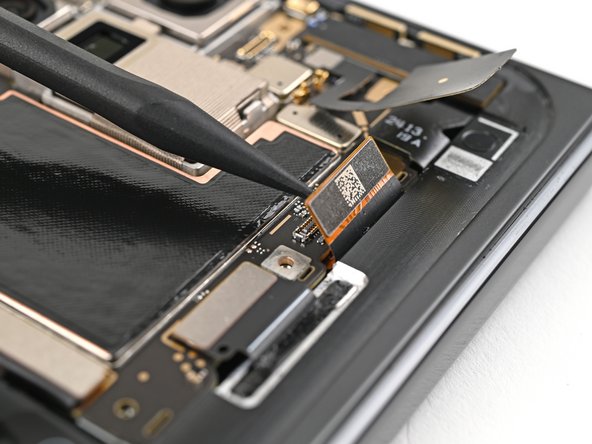
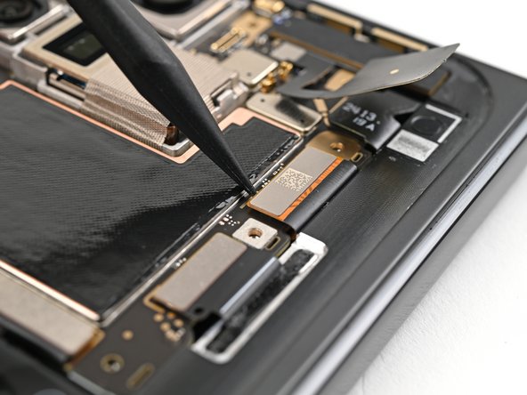
Step 30
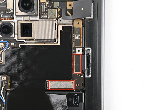
– Give it another go! Disconnect those top and bottom interconnect cable press connectors by gently prying them next to the shiny gold markers. You’ve got this!
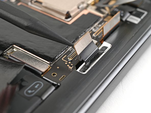
Step 31

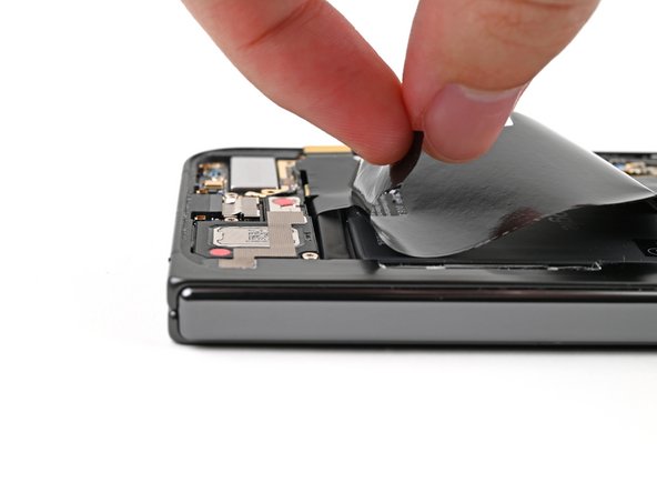
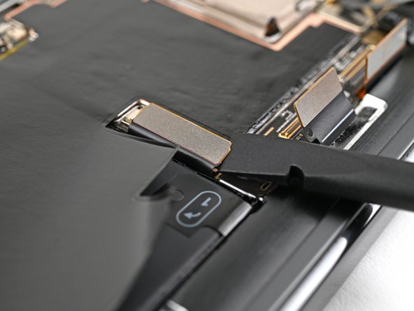
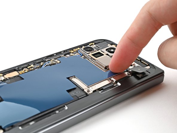
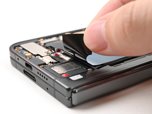
– Gently peel off the graphite sheet from the bottom speaker, letting the adhesive naturally separate.
Step 32
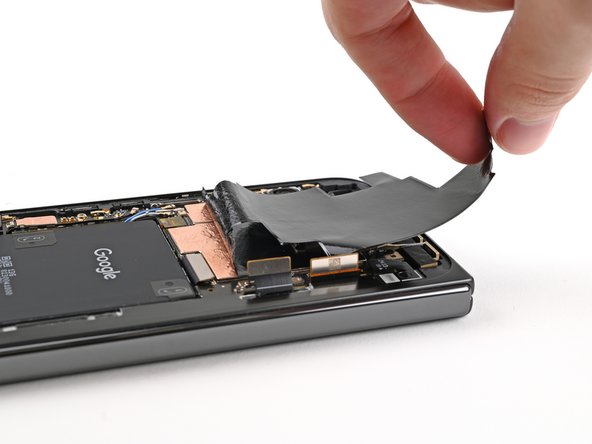
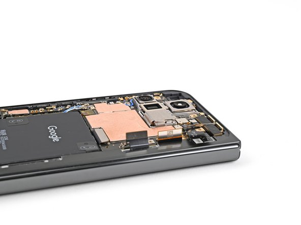

– Keep peeling that graphite sheet away from the logic board to free up the last bits of adhesive. You’re doing great!
Step 33

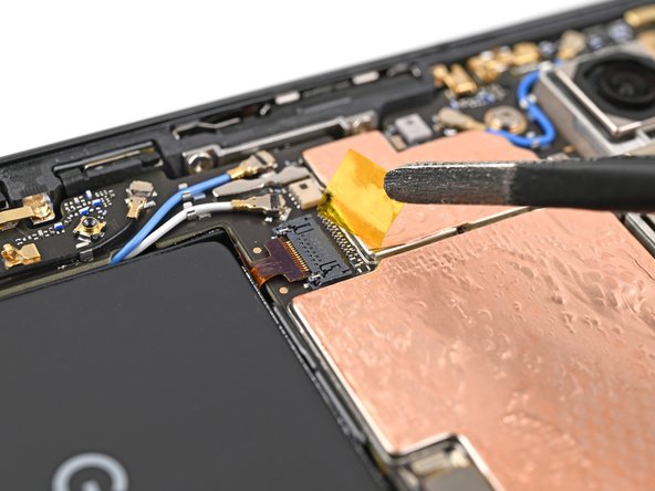
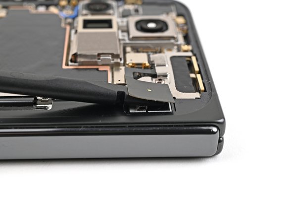
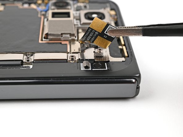
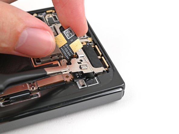
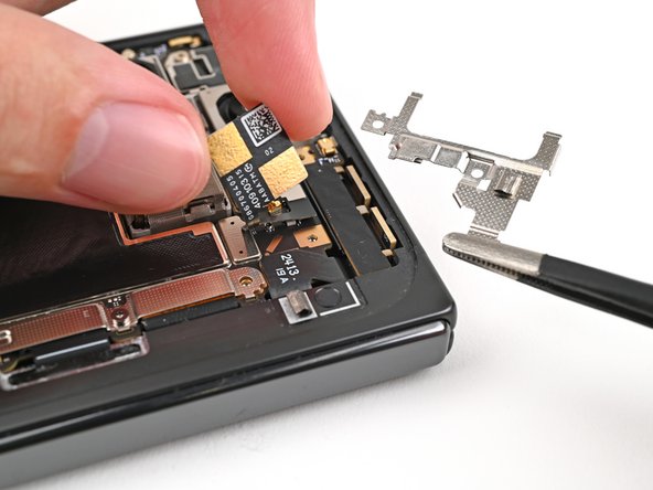
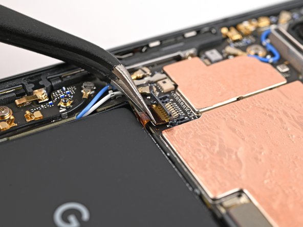
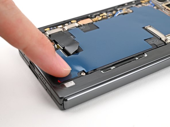
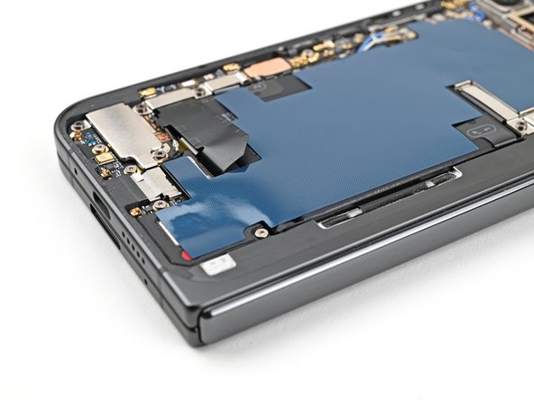
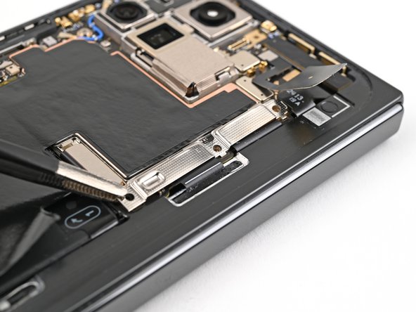
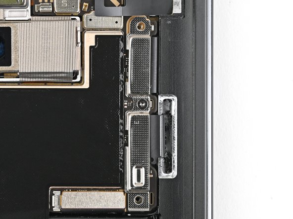
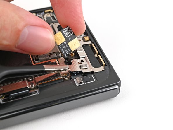
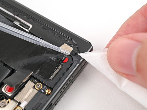
– Grab your trusty tweezers or just use your fingers to gently peel off that yellow tape from the side button cable ZIF connector. It’s like unwrapping a present!
– Set that tape aside for now; you’ll want it back during reassembly, so keep it safe!

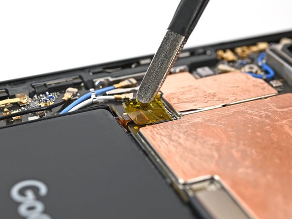
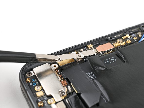
Step 35

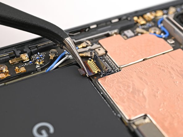
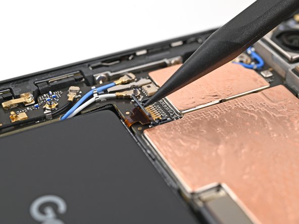
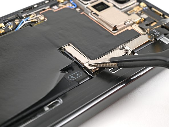
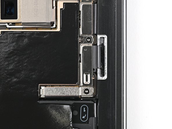
– Grab those angled tweezers and gently coax the side button cable out of its snug little home. You’ve got this!
Tools Used
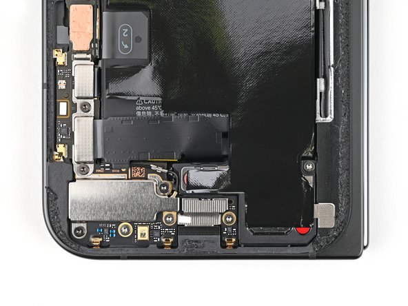
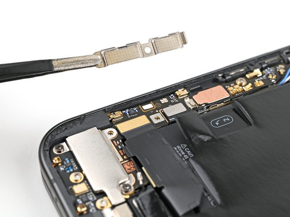
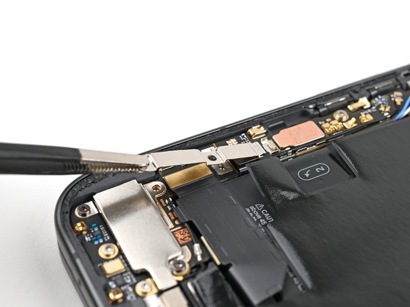
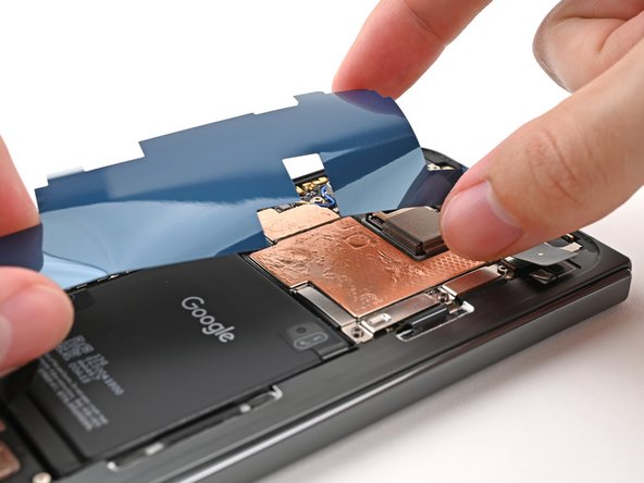
Step 36

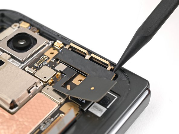
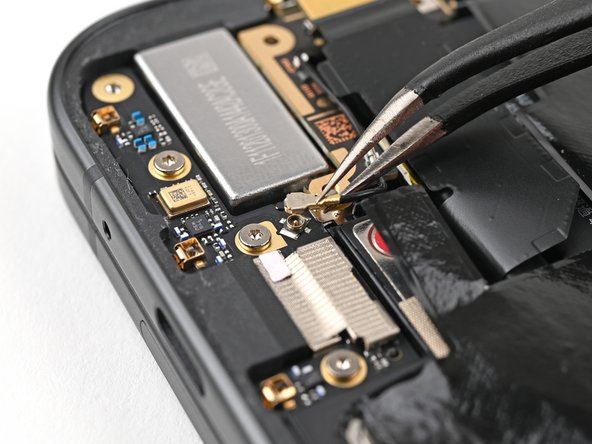
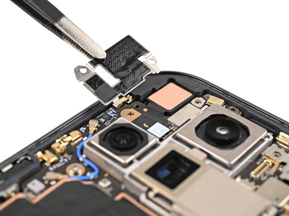
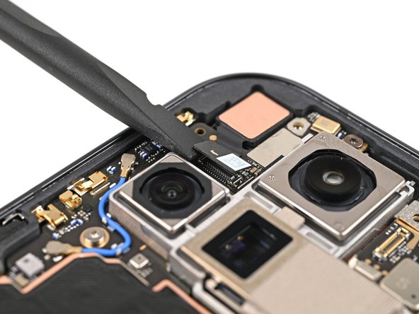
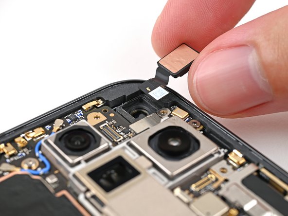
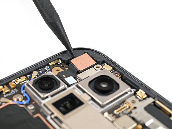
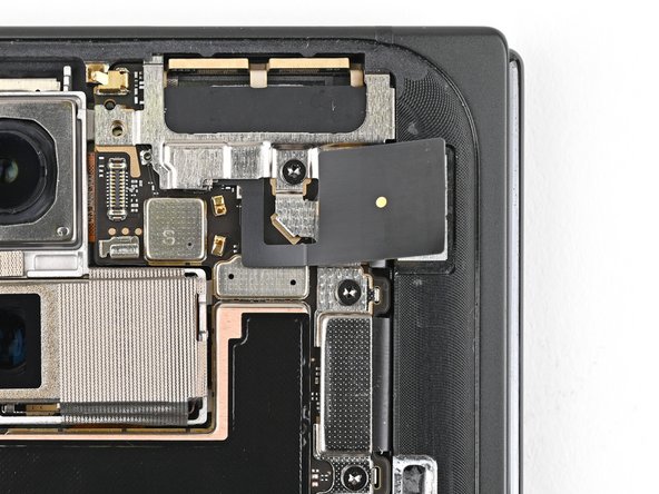
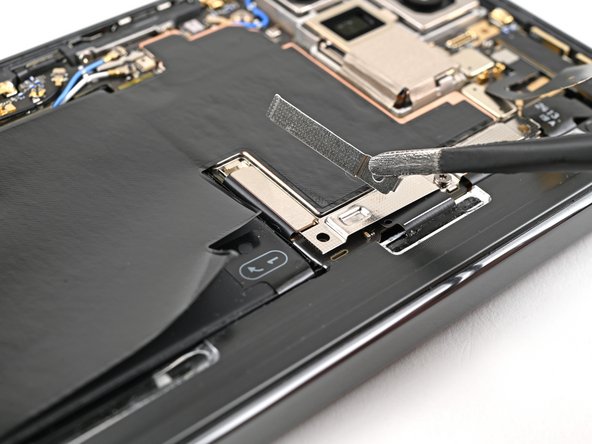
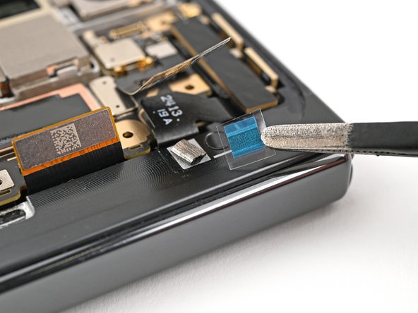
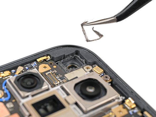
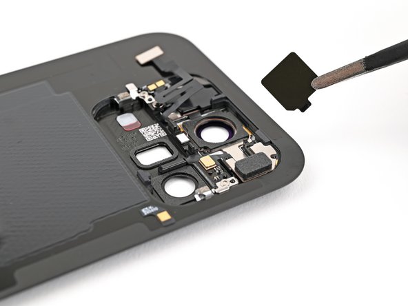
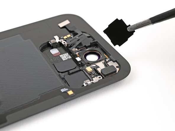
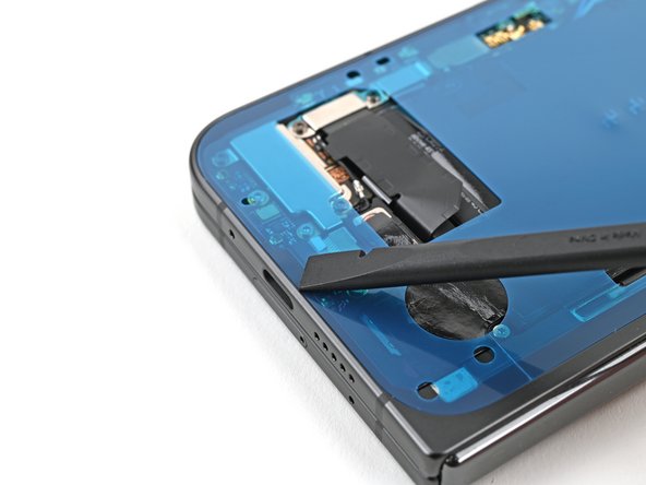
A thermal pad gently keeps the 5G mmWave antenna snug against the frame, ensuring everything stays nice and cozy.
– Gently slide the tip of your spudger in there and give the 5G mmWave antenna a little nudge to lift it away from the frame. Make sure to separate it carefully from the thermal pad while you’re at it!
Tools Used
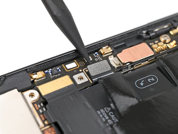
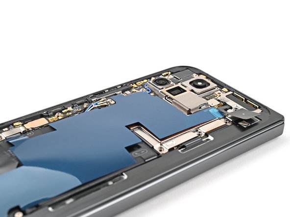
Step 37
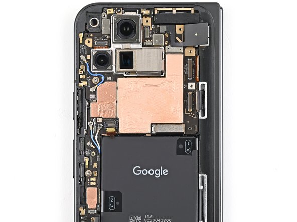

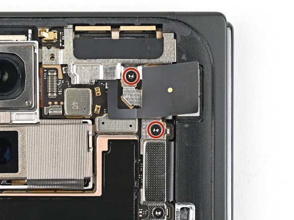
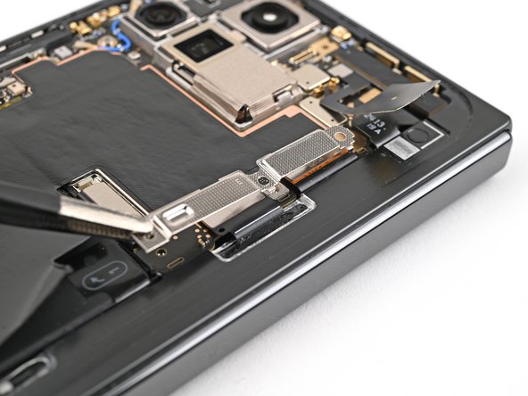
– Grab your trusty Torx Plus 3IP driver and let’s get to work on those screws holding the logic board in place:
– First up, we have one little screw that’s 2.2 mm long—easy peasy!
– Next, you’ll find two slightly bigger screws, each measuring 2.6 mm—you’re doing great!
Step 38

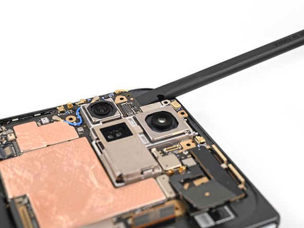
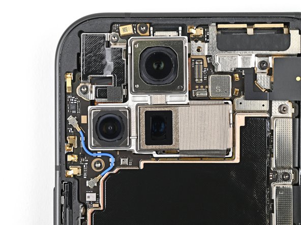
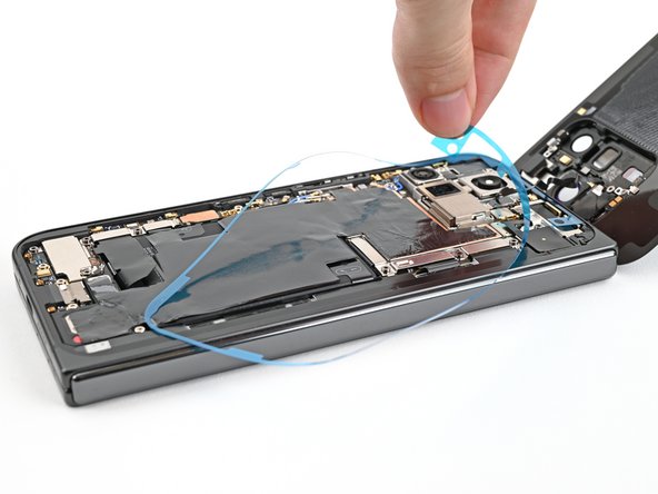
It might feel a little tough since the logic board is glued to the frame with some special goo. Don’t worry, it’s all part of the fun!
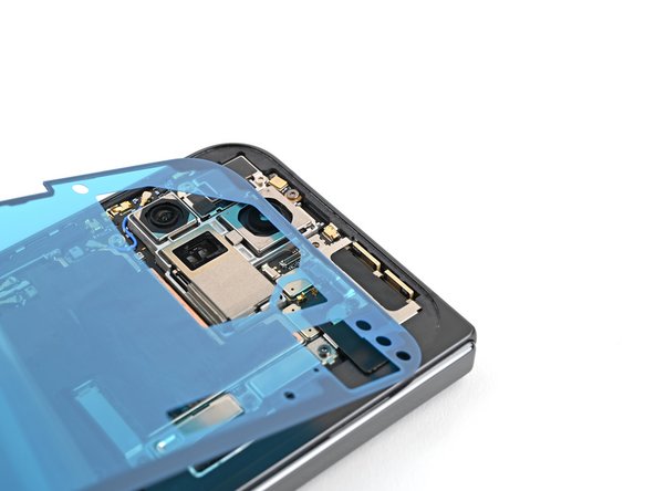
– Hey! So you’re gonna wanna insert that handy-dandy flat end of your spudger under the top left corner of the logic board, right beside the inner front camera cutout. Once it’s in, give it a gentle nudge and you should be able to grip the top edge. That’s it, you’re doin’ great!
Tools Used
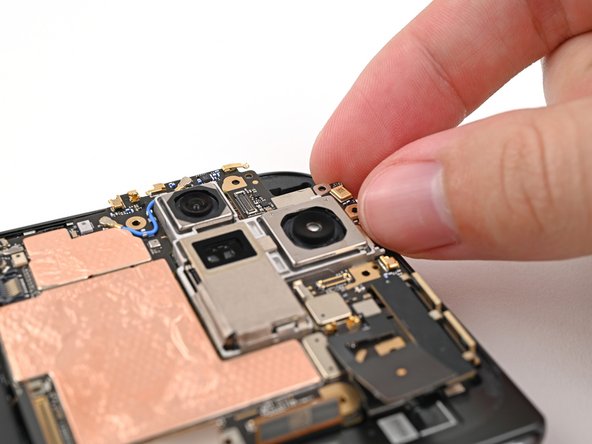
Step 39
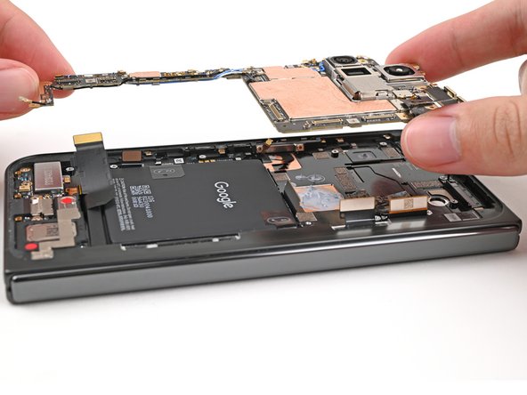
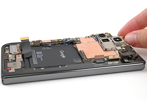
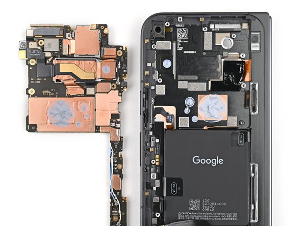
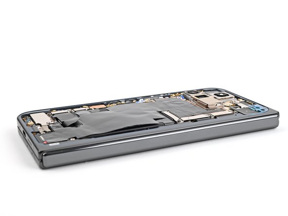
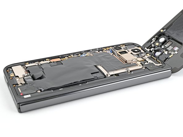
– Gently lift the top of the logic board out of its cozy frame and set it free.
– Carefully flip the logic board over and place it on a clean surface, ready for its next adventure.
Step 40
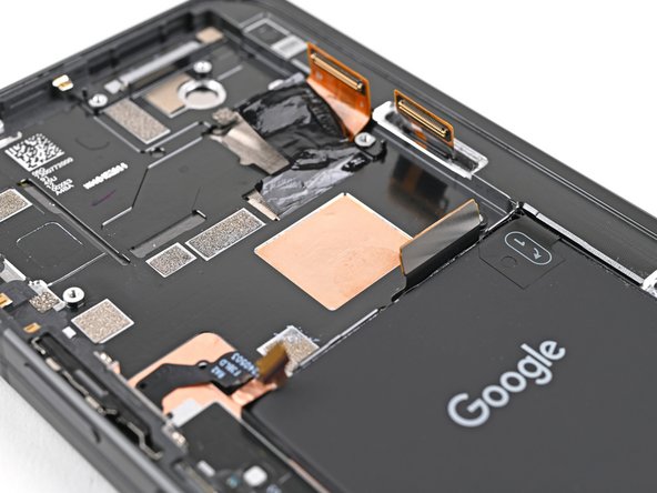
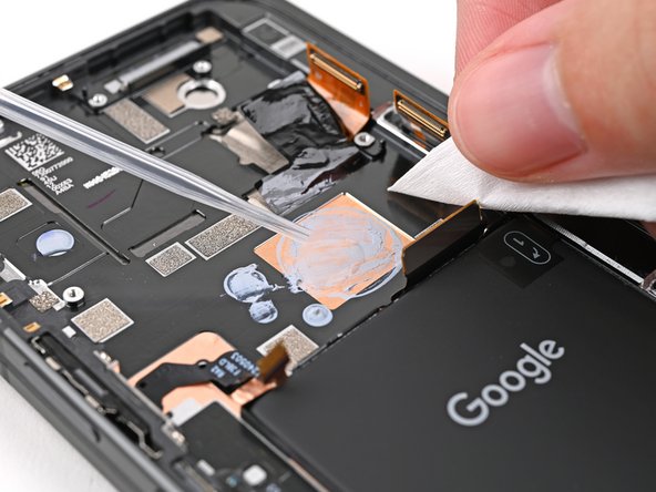

– Grab your spudger and gently scrape off the chunky bits of old thermal paste from the frame—think of it as peeling off a sticker.
– Dab a bit of high-strength isopropyl alcohol (90% or more) on any stubborn paste remnants—it’s like magic eraser juice.
– Polish it off with a coffee filter or lint-free cloth for a squeaky-clean finish. If you’re stuck, you can always schedule a repair.
Tools Used
Step 41
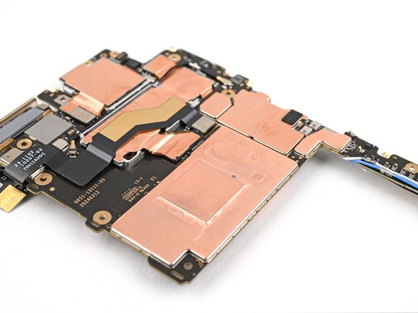
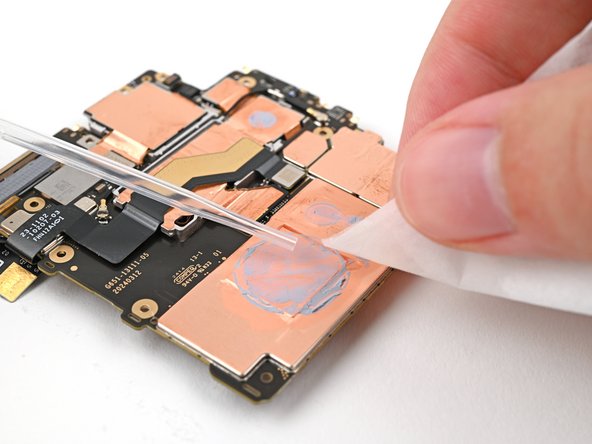

Be gentle with the logic board while giving it a clean! Pressing too hard might lead to bending those little metal springs or leaving smudges on the rear camera assembly. Let’s keep it neat and tidy!
– Time to give the bottom of the logic board the same thermal paste TLC you just did. You’ve got this!
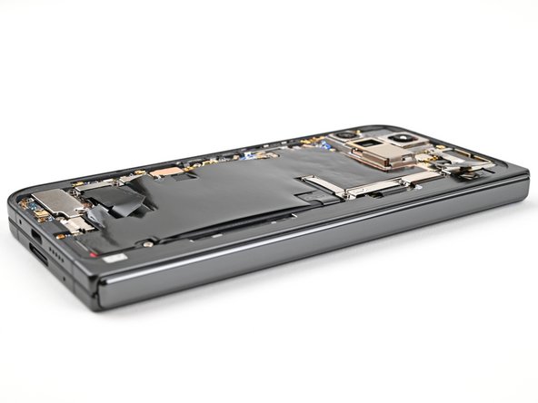
Step 42

– Way to go on finishing the disassembly! Now, let’s dive into the next steps to get your device all put back together and ready for action.
Step 43
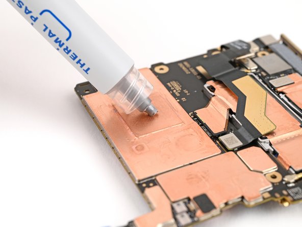
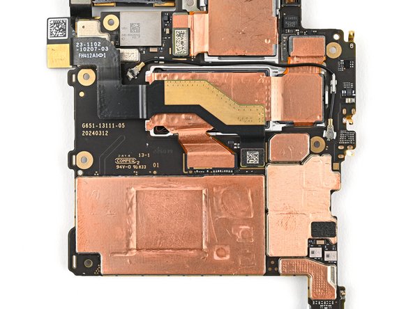

– Dot the motherboard with five small beads of thermal paste, placing them where the old paste was.
Step 44


– Gently slide the logic board back into its spot in the frame, ensuring all cables are free and clear—no squished wires allowed!
Step 45


– Grab your trusty Torx Plus 3IP driver and let’s get those screws in place to secure the logic board:
– One screw that’s 2.2 mm long, just the right size!
– And two more screws, each measuring 2.6 mm long, to keep everything snug and secure!
Step 46

– Grab those angled tweezers and gently nudge the side button cable back into its cozy little slot. Easy peasy!
Tools Used
Step 47

– Gently flip that locking tab down and give it a light press until you hear that satisfying click—it’s locked and ready to roll!
Step 48

– Grab that yellow tape and lay it gently over the ZIF connector and its cable. You’ve got this!
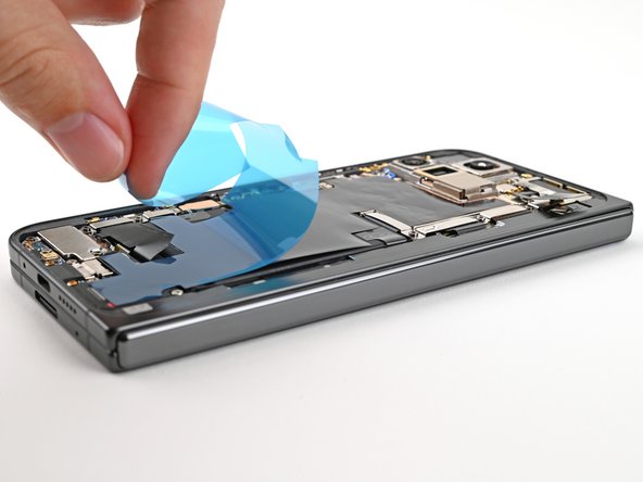
Step 49

– Start by peeling away the clear liner from your shiny new graphite sheet, revealing the sticky goodness on the top half.
– Next, carefully position the upper half of that graphite sheet right over the logic board and gently lay it down in place.
Step 50

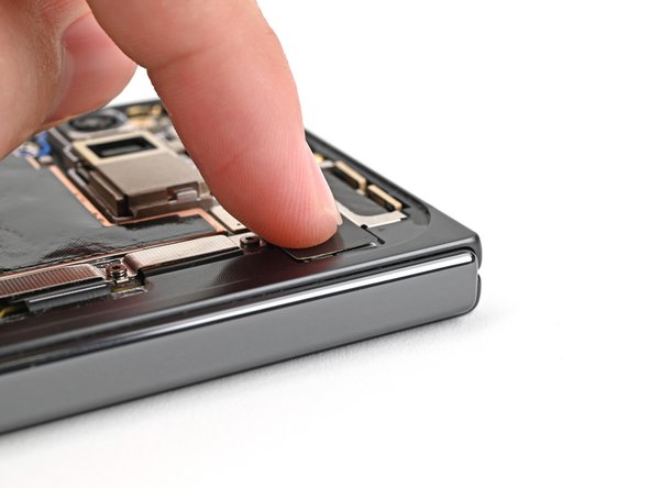
– Give that upper half of the graphite sheet a gentle press with your finger to snugly fasten it to the logic board. You’re doing great!
Step 51

– Peel away the blue liner from the bottom of the graphite sheet to reveal the sticky goodness underneath.
Step 52

– With a little finesse, drag your finger gently from the center of the graphite sheet right over to the adhesive spot on the loudspeaker. This will help you flatten the graphite sheet and stick it down nice and snug!
Step 53

– Grab that handy pull tab at the top of the graphite sheet and gently peel away the remaining liner. You’re almost there!
Step 54
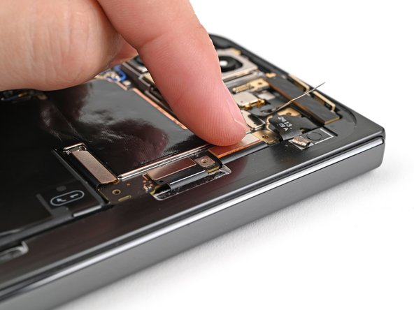

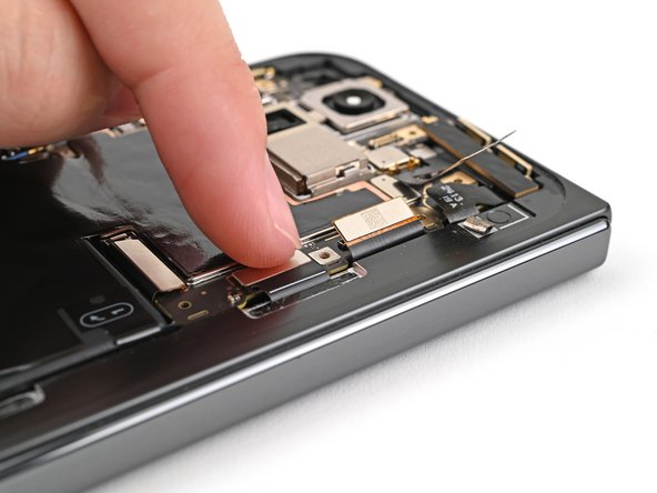
– Now, hook up those display cables – the inner one and the top and bottom interconnect ones. Gently press the connectors into place.
Step 55

– Carefully tuck that inner display cable bracket clip back into its cozy spot on the logic board and make sure those screw holes are perfectly lined up. You’ve got this!
Step 56

– Grab your trusty Torx Plus 3IP driver and go ahead and secure that inner display cable bracket with the 3.0 mm-long screw. You’ve got this!
Step 57

– Pop that bottom interconnect bracket clip back into its cozy spot in the frame and line up the screw hole like a pro!
Step 58

– Grab your trusty Torx Plus 3IP driver and let’s get to work! Carefully install that 3.0 mm screw to keep the interconnect cable bracket snug and secure. You’ve got this!
Step 59

– Keep that ultra wideband antenna out of the way like a pro! Now, slide the ultra wideband bracket clip back into its cozy spot in the frame and make sure those screw holes are lined up just right.
Step 60


– Grab your Torx Plus 3IP driver and secure the ultra wideband bracket with the two 3.0 mm-long screws. Easy peasy!
Step 61

If your ultra wideband bracket’s adhesive is still sticking around like a loyal buddy, no need to mess with it—skip ahead.
– Say goodbye to the old adhesive and foam on the ultra wideband bracket and beneath the antenna. It’s time for a fresh start!
– Now, let’s give that bracket and frame a little love with some new adhesive and foam. They deserve it!
– Gently press the ultra wideband antenna back onto the frame and make sure it sticks like a champ!
Step 62

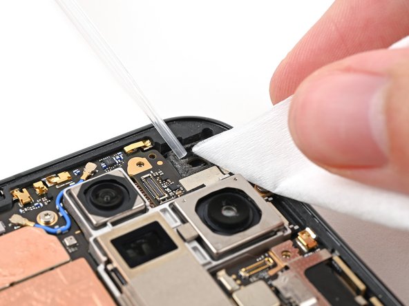
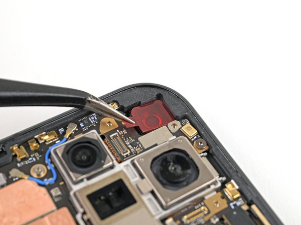
– Time to ditch that old adhesive foam from the inner front camera cutout! Use tweezers or your fingers to gently remove it.
– Next, give those pesky adhesive residue remnants a good clean. We recommend using isopropyl alcohol (>90%) and a coffee filter or lint-free cloth to get the job done.
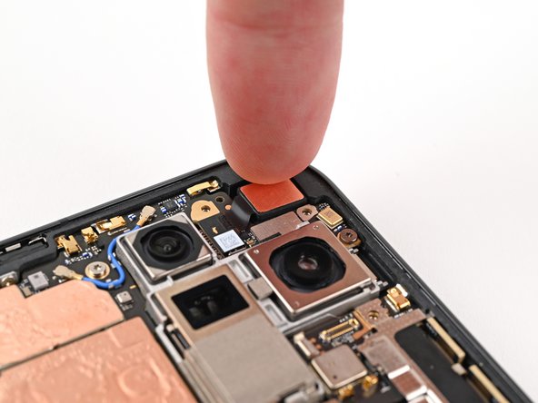
Step 63

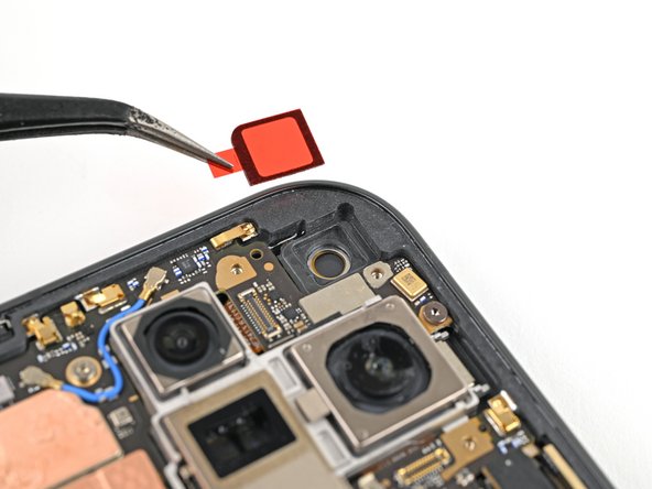
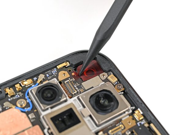
– Gently peel away the clear liner from the sticky adhesive foam for the replacement inner front camera, revealing its sticky side. It’s like unwrapping a gift, but for your phone!
– Carefully position the adhesive foam over the cutout in the frame, ensuring that the pull tab is pointing downwards, just like the perfect selfie angle.
– Now, place that adhesive right in the cutout. You’re almost there!


Step 66

– While you’re holding the inner front camera above its cozy little cutout, give its press connector a friendly reconnect.
– Now, gently place the inner front camera into its snug cutout and press down firmly to make sure it’s happily secured to the adhesive.
Step 67

– Now, pop that inner front camera bracket clip back into its little home on the logic board. Make sure those screw holes line up – it’s like a puzzle, but way cooler!
Step 68


– Grab your trusty Torx Plus 3IP driver and let’s get to it! Carefully install those two 2.6 mm-long screws to hold the inner front camera bracket nice and snug. You’ve got this!

Step 70

– Gently place the vibrator bracket onto the logic board, making sure to line up those screw holes like a pro!
Step 71

– Grab your trusty Torx Plus 3IP driver and let’s get those two 3.0 mm-long screws in place to secure the vibrator bracket. You’ve got this!


Step 74

– Slide the base battery bracket clip back into its cozy spot on the logic board and make sure those screw holes are lined up just right.
Step 75


– Grab your trusty Torx Plus 3IP driver and get ready to pop in those two 3.0 mm-long screws that hold the base battery bracket in place. You’ve got this!
Step 76

– Use a spudger, or your fingers, to gently peel off the old back cover adhesive. It’s like removing a sticker, but a little more satisfying.
– Wipe away any leftover adhesive with isopropyl alcohol (>90%) and a coffee filter or a microfiber cloth. Think of it as a spa treatment for your device.
Tools Used
Step 77

If you’re swapping out your back cover for a shiny new one, go ahead and tackle the next two steps. If not, feel free to breeze right past them!
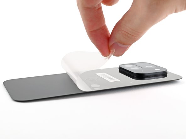
– Grab your tweezers or use those nimble fingers of yours to pluck out the three rear camera liners from your shiny new back cover. Easy peasy!


Step 80

Take it easy during this step! It’s super easy to accidentally place the adhesive in the wrong spot. So, slow and steady wins the race—your patience will pay off!

Step 82

– As you peel away the remaining clear liner, gently position the rest of the adhesive around the edges of the phone. Take your time and make sure it sticks just right!

Step 84

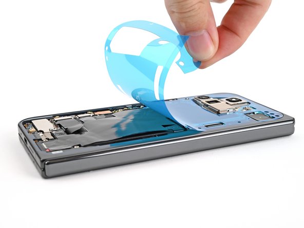
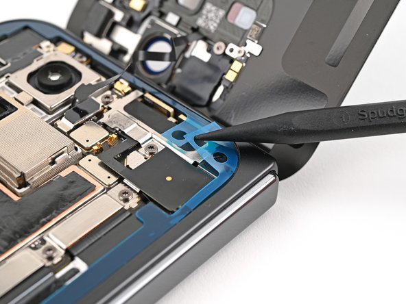
– Grab your trusty spudger and gently pry up the segmented tab located at the bottom right corner of that snazzy blue liner.
– Once the tab is up, give it a little lift and peel away the large blue liner to reveal the hidden secondary liner beneath. You’re doing great!
Tools Used
Step 85

Take it slow! If you’re having a little trouble, just gently reposition it and try again. Don’t force it!
– While keeping the back cover steady or propped up, go ahead and plug in that back cover cable.
Step 86

– Slide the top bracket clip back into its cozy spot on the logic board and make sure the screw hole is lined up just right.
Step 87

– Use a Torx Plus 3IP driver to install the 3.0 mm‑long screw securing the top bracket. You got this!

Step 89

– Time to peel back that second layer and reveal the sticky stuff! Don’t worry, it’s just there to hold things in place. You’ve got this!
Tools Used
Step 90

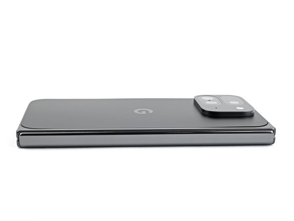
– Line up the top edge of the back cover with the frame and give it a firm press to stick it in place. Easy peasy!
Step 91

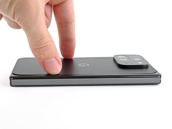
If you’re feeling extra fancy, you can use a hair dryer or heat gun to warm up the edges of the back cover. It might help things stick together a little better. But hey, it’s your call!
– You did it! Pat yourself on the back for a job well done.
– Remember to recycle your e-waste responsibly at an R2 or e-Stewards certified recycler.
– Hit a snag? No worries—try some troubleshooting or reach out to our community for tips.
– Cancel: I didn’t finish this guide.
–
Success!