DIY Guide: Google Pixel 8a Vibration Motor Replacement
Duration: 45 minutes
Steps: 40 Steps
Hey there! This awesome repair guide sure didn’t come from us. Don’t fret though, check out more about these handy-dandy steps on our site. Trust us, you won’t want to miss it!
Ready to rock your Google Pixel 8a’s vibe game again? Let’s replace that vibration motor! You know, the little fella that gives your phone its sweet rumble. If it’s gone silent or feelin’ weak, it’s time for a refresh. We’ll need some new back cover and flash unit adhesives to make sure everything is snug as a bug. Just a heads-up: messing with your phone’s innards might make it a little less water-resistant. How well you stick that back cover adhesive back on will determine how splash-proof it stays. If you need help, you can always schedule a repair.
Step 1


Make sure to let your Pixel’s battery dip below 25% before jumping into this repair adventure. A fully charged lithium-ion battery can be a bit of a firecracker if it gets damaged, so let’s keep things safe and sound!
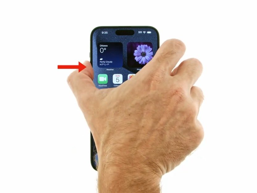
Press both the power and volume up buttons simultaneously to open the shutdown menu.
– First things first! Go ahead and disconnect all those cables from your phone. We want it to be free and clear.
– Now, let’s ensure your phone is fully powered down. Shut it off completely, so it can relax a bit while we work our magic.
Step 2


– Give that SIM eject tool, a straightened paper clip, or whatever you’ve got a good press into the SIM card tray hole on the left side of your phone until the tray pops out like it just heard a great joke.
– Now, gently pull out the SIM card tray and set it aside like it’s taking a little break.
Step 3


Hey there, techie! The back cover is held down by some sticky stuff around the edges and by the cameras. Don’t worry, it’s totally doable! Just remember, you need to be extra careful here to keep those phone guts safe. Think of it like a delicate dance. We’re going to gently ease those parts apart without making things messy. If you need help, you can always schedule a repair
– Just a friendly reminder, keep your tool within 3 mm of the edges – that’s about the width of the flat part of your opening tool. We want to keep things safe and sound!
– And hey, steer clear of sliding your tool under the edges of the camera bump. We wouldn’t want to disturb any delicate parts!
Step 4


Your trusty opening tool is equipped with a flat end and a curved end. As you embark on the opening journey, grab the flat end and tilt it just right so the sharp edge is aiming skyward. You’ve got this!
– Gently slide the edge of your trusty opening tool between the back cover and the frame. Start with the sharp corner to make it easier to break free from that adhesive grip.
Step 5


– Gently glide your trusty opening tool along the bottom edge to break free the adhesive that’s keeping the back cover snug as a bug.
Step 6


– Guide your opening tool around the bottom right corner, then cruise up the right edge until you hit the bottom of the camera bump.
– Lift your opening tool out from under the back cover.
Step 7


– Gently slide your opening tool under the top right corner of the back cover, right above that little camera bump. You’re doing great!
– Now, glide your tool along the top edge until you reach the top left corner, just above the camera bump. Keep it smooth!
– Finally, carefully take your opening tool out from under the back cover. You’ve got this!
Step 8


– Gently slide your trusty opening tool under the left edge of the back cover, right beneath that camera bump you’re so familiar with.
– Carefully glide your tool down the left edge to break free the adhesive holding things together.
Step 9


A strip of adhesive above the camera bump is holding the top edge of the back cover in place. You can slip your opening pick up to 3mm along the top edge to help loosen things up.
– Gently slide an opening pick under the top left corner of the back cover, aiming for that sweet spot just near the top edge of the camera bump.
– Now, glide the pick to the right, and stop right when you hit the right edge of the cameras. You’re doing great!
Step 10


A last little strip of adhesive right under the camera bump keeps the back cover snug and secure.
– Slide the slim edge of an opening pick right under the back cover, just a smidge below the camera bump.
– Now, grab a second opening pick and pop it in the same spot on the opposite side.
Step 11


Handle the back cover like it’s your favorite pizza slice—gentle and with care! If the adhesive is putting up a fight, give the cover a little shimmy side-to-side to help loosen things up.
If the adhesive is being a bit stubborn, try giving the back cover a gentle warm-up just below the camera bump using a hair dryer or iOpener. This will help loosen things up a bit and make your life easier.
– Now, grab both your picks and give that adhesive a good ol’ fashioned pry-up. Keep the pressure on and watch that back cover pop right off. You’re practically there!
Tools Used


Step 12


– Time to ditch that back cover! It’s like saying goodbye to an old friend (don’t worry, you’ll be seeing it again soon).
– Now, before you put everything back together, it’s always a good idea to give your phone a quick test drive. See if it’s ready to rock and roll! Power it up, make sure everything is running smoothly, then power it back down before you continue.
– Let’s get this thing back together, shall we? Follow these steps to put your back cover back in place, good as new!
Step 13


Just warm up the flash a bit—like a cozy hug! Remember, the battery and its buddies can be sensitive to heat, so let’s keep it gentle.
Or you could go the old-school route and use an iOpener or heat gun to warm things up!
– Grab your trusty hair dryer and give that flash unit a little warm-up. It’s time to loosen up that adhesive holding it to the logic board cover.
Tools Used

Step 14


Handle the flash cable with care, it’s like a delicate butterfly—super fragile!
Step 15


As you dive into this repair, remember to keep an eye on those screws! Track each one and put it right back where it belongs—trust us, future you will thank you!
The Pixel 8a’s got Torx Plus screws, but don’t worry! Standard Torx bits will do just fine. Just make sure to apply a steady downward pressure to keep things from getting stripped. You’ve got this!
– Grab your trusty Torx Plus 3IP screwdriver and loosen up those 15 screws holding down the logic board cover:
– Thirteen screws are 4.3-mm long
– The remaining two are 1.9-mm long
Step 16


Take it easy and watch out for those spring contacts around the edge of your phone! Make sure to only use your tool where it’s shown—let’s keep everything safe and sound.
– Slide an opening pick into the bottom right corner of the logic board cover and gently lift up to free that stubborn clip.
– Carefully wedge the tip of a spudger under the notch near the top right corner of the logic board cover, just below the screw hole, and give it a little nudge to pop that clip loose.
Tools Used

Step 17


– Gently lift the top edge of the logic board cover and give that flash unit a little wiggle room – it’s time for it to make its grand exit through its cutout.
– When you’re putting everything back together, remember to guide that flash unit through its cutout as you lower the logic board cover back into place. It’s like a little dance, and it needs to go smoothly!
Step 18


– Time to get your hands a little dirty! Gently lift off the logic board cover, which is home to the wireless charging coil. Just a little finesse, and you’re on your way!
Step 19


– Grab some tweezers or just use your fingers to gently pop off the metal cover on the right side of your phone. You’ve got this!
– When it’s time to put everything back together, tuck the upper left corner of the cover under the hook on the logic board before settling it down into place. Easy peasy!
Tools Used

Step 20

This guide is tailored for the Verizon model (G8HHN) Pixel 8a, which features an additional cable and connector for the 5G mmWave antenna, conveniently located just to the left of the battery connector. If you’ve got the non-mmWave version, feel free to breeze past any steps that mention the antenna cable. You’ve got this!
Step 21


To keep the surface-mounted components around the battery and 5G mmWave connectors safe and sound, make sure to only pry where we say to. You’re doing great!
To join that connector back together, just line it up over the socket and give a gentle press on one side until you hear that satisfying click. Then, do the same on the other side. It may take a couple of attempts to get everything lined up just right, but don’t worry – you’ve got this! If you need help, you can always schedule a repair.
– Slide the flat end of a spudger under the right edge of the battery press connector and gently pry it upwards to disconnect it. You got this!
Tools Used


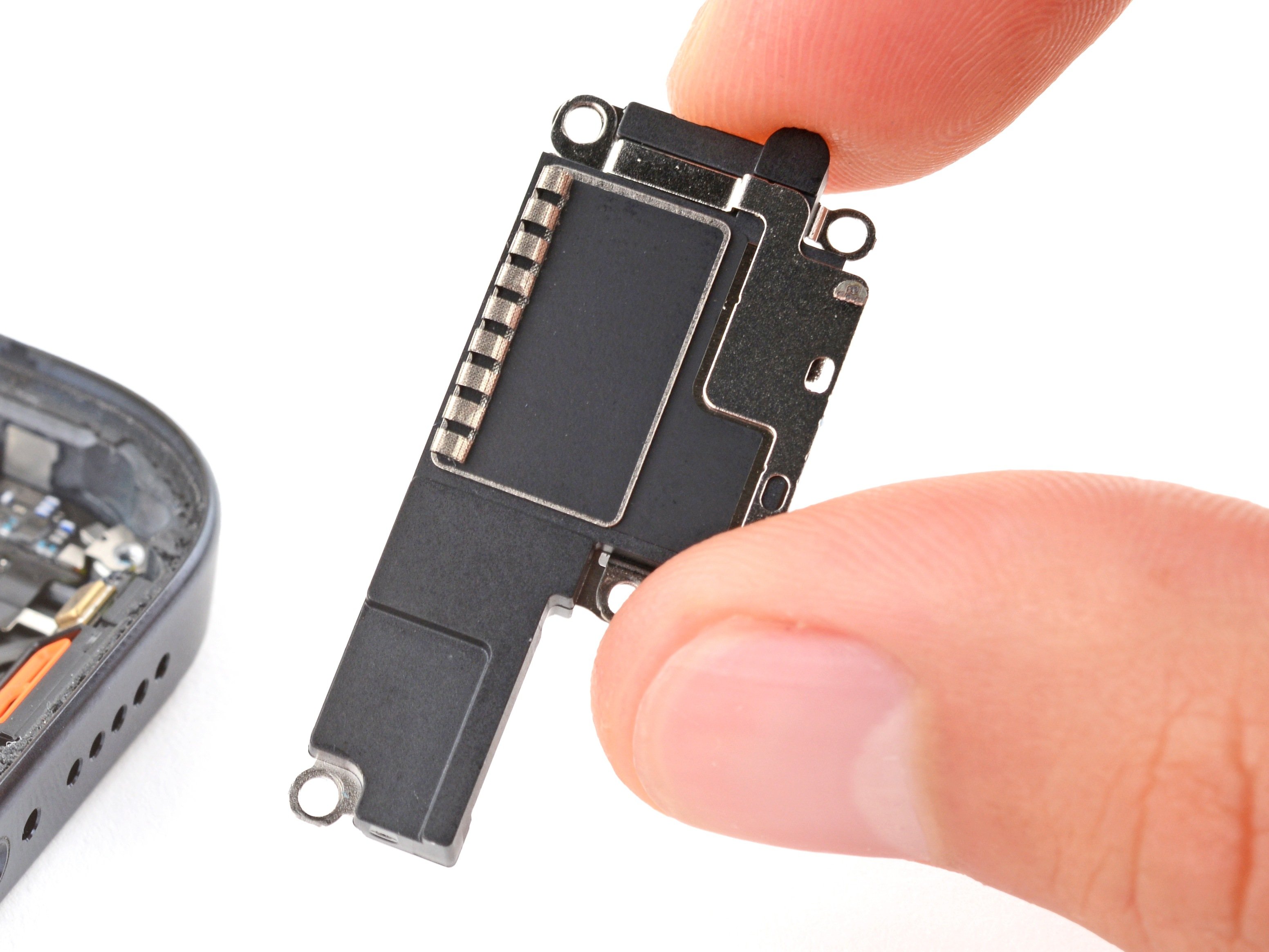
Step 23


– Grab your trusty Torx Plus 3IP screwdriver and get ready to rock! It’s time to unscrew that 4.3 mm-long screw that’s keeping the earpiece speaker snug as a bug in the frame. Let’s do this!
Step 24


– Gently lift the bottom edge of the earpiece speaker and pop that baby out!
– When you’re ready to tuck the speaker back in during reassembly, just keep the graphite film clear of the way. Then, slide the speaker in at a nice downward angle and push it towards the front of the phone so the gasket fits snugly into its cozy spot in the frame.
Step 25


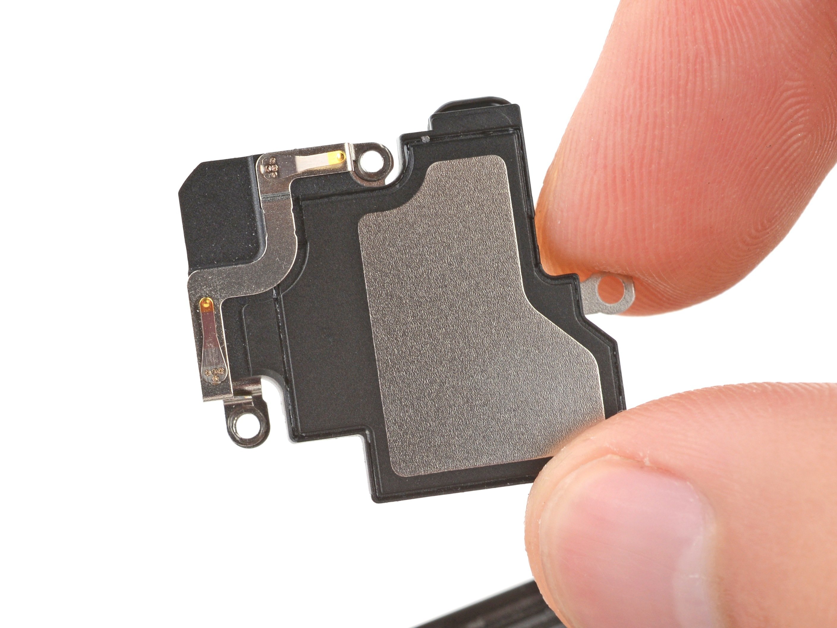
– Grab your trusty Torx Plus 3IP screwdriver and gently remove the two screws that are 4.3 mm long, keeping that antenna housing nice and secure. You’ve got this!
Step 26


– Slide an opening pick under the left edge of the antenna housing and lift to pop the clips holding the housing.
– Do the same along the top edge to release the remaining clips.
– When reassembling, press firmly around the housing edges to snap the clips back into place.
Step 27


– Give that antenna housing a little lift and pop it right off. It’s like giving your device a mini-makeover!
Step 28


Watch out for those rear camera lenses! Keep your hands off them during the next two steps, alright?
– Gently use the tip of a spudger or your trusty fingernail to lift up and disconnect the press connector located just above the battery. You’ve got this!
Tools Used
Step 29


If the pick is having a tough time sliding under the cable, give the cable a little warmth using a hair dryer or heat gun. This will help loosen up that stubborn adhesive hiding underneath.
– Gently slide the tip of your opening pick beneath the right side of the front-facing camera cable and give it a little lift to release it. You’ve got this!
Tools Used


Step 31


Handle the spring contacts on the edges of the logic board with care, they’re delicate little guys! Make sure to only insert your tool exactly where we say to.
– Take your trusty spudger and gently slide it under the notch at the top right corner of the logic board. Give it a little nudge upward to pop the board free.
– Now, let’s do the same on the other side! Use the notch to the left of the cameras and carefully pry up the board.
Tools Used
Step 32


The logic board is a bit of a diva—handle it with care as you gently ease the lower edge out of the frame.
Hold your horses! Don’t yank the logic board out just yet; it’s still attached to the frame by the screen cable.
Before you dive in and tackle the board, don’t forget to pop out that SIM tray first!
Keep an eye out for the flash, front-facing camera, and press connector—let’s make sure they don’t get stuck under the frame!
– Alright, let’s get this logic board out of its frame. First, give the top edge a little lift.
– Now, slide that logic board to the right, like you’re giving it a high five. You’ll see it lift over the little bits and bobs in the frame.
– Keep sliding, and the charging port will come right out of its little nook.
– To put it all back together, just gently push the logic board down towards the bottom and press the charging port in until it sits snugly.
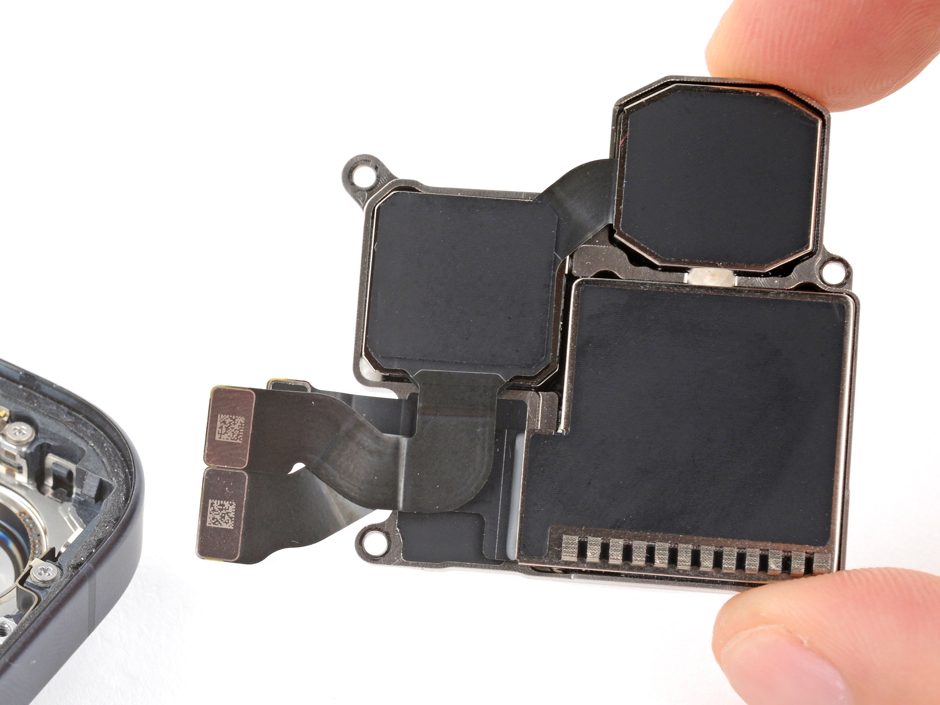
Step 33


Hey there! Don’t let the logic board have a wild ride during this step – keep it steady but don’t go all ogre with the camera lenses or connectors. Also, give the thermal pads on the underside of the logic board a wide berth!
If you don’t have a suction handle, just lean your phone against something sturdy, like a hefty box or a thick book. You’ve got this!
– Grab a suction handle and stick it on the left side of the screen, with the handle pointing down like it’s ready for a hug!
– Now, give your phone a little boost; prop up the left side so it stands tall and proud.
– Gently tilt the logic board down, and with care, lay it flat, making sure to guide the delicate graphite sheet around those fragile cables like a pro.
Tools Used

Step 34


Take it easy and steer clear of poking that battery during this step!
Keep one hand hovering above the display bracket while you pry it up, because that bracket has a mind of its own and could pop right out!
Watch out for the board hiding under the bracket’s socket! Just slide your tweezers in gently—only enough to lift the bracket.
If your display cable bracket is looking a bit wonky and doesn’t quite fit, it’s time to swap it out for a shiny new one!
– Alright, let’s get that display cable bracket off! Using the tip of one arm of your angled tweezers, gently pry up the top edge of the bracket from its home on the logic board.
– Now that you’ve pried it up, give that bracket the boot! Remove it completely.
– When you’re putting everything back together, remember to hook the bottom edge of that bracket into its slot on the logic board. Then, give the top a firm press to snap it back into place.
Tools Used
Step 35


– Gently slide the flat end of a spudger or your perfectly clean fingernail under the top edge of the display cable press connector and give it a little nudge upwards to disconnect it.
– Reconnecting this cable can be a bit of a puzzle due to its tension. If it’s being stubborn, grab some tweezers to hold the neck of the cable steady while you align it with the socket. Once it’s all lined up, press down gently to secure it in place.
Step 36


– Hey there! Let’s get this party started on the right foot. Time to pull that logic board from its frame. It’s smoother than a dance move, and you’ve got this! Don’t sweat it, we’ll be right by your side. 🚀 If you need just a little extra help, you can always schedule a repair.
Step 37


Keep your fingers and tools away from the sensor – it’s a delicate little guy that prefers its personal space!
– If that cheeky front sensor rubber gasket decided to stick to the frame or got a bit out of alignment, just give it a gentle nudge and set it aside for now.
– When you’re putting everything back together, make sure to pop that gasket back over the front sensor on the logic board, aligning the smaller cutout towards the top like a pro.
Step 38


– Alright, let’s talk reassembly:
– First up, take a peek at those thermal pads—they’re chilling on the bottom of the logic board or right on the frame’s right side.
– If you’re bringing back your trusty logic board and notice any thermal pads looking worse for wear, gently peel off the old pad, give the surface a good clean with some high-octane isopropyl alcohol (90% or stronger), and pop on a fresh pad.
– Got a new logic board that didn’t come with thermal pads? No worries! Slap those new pads on now.
Tools Used

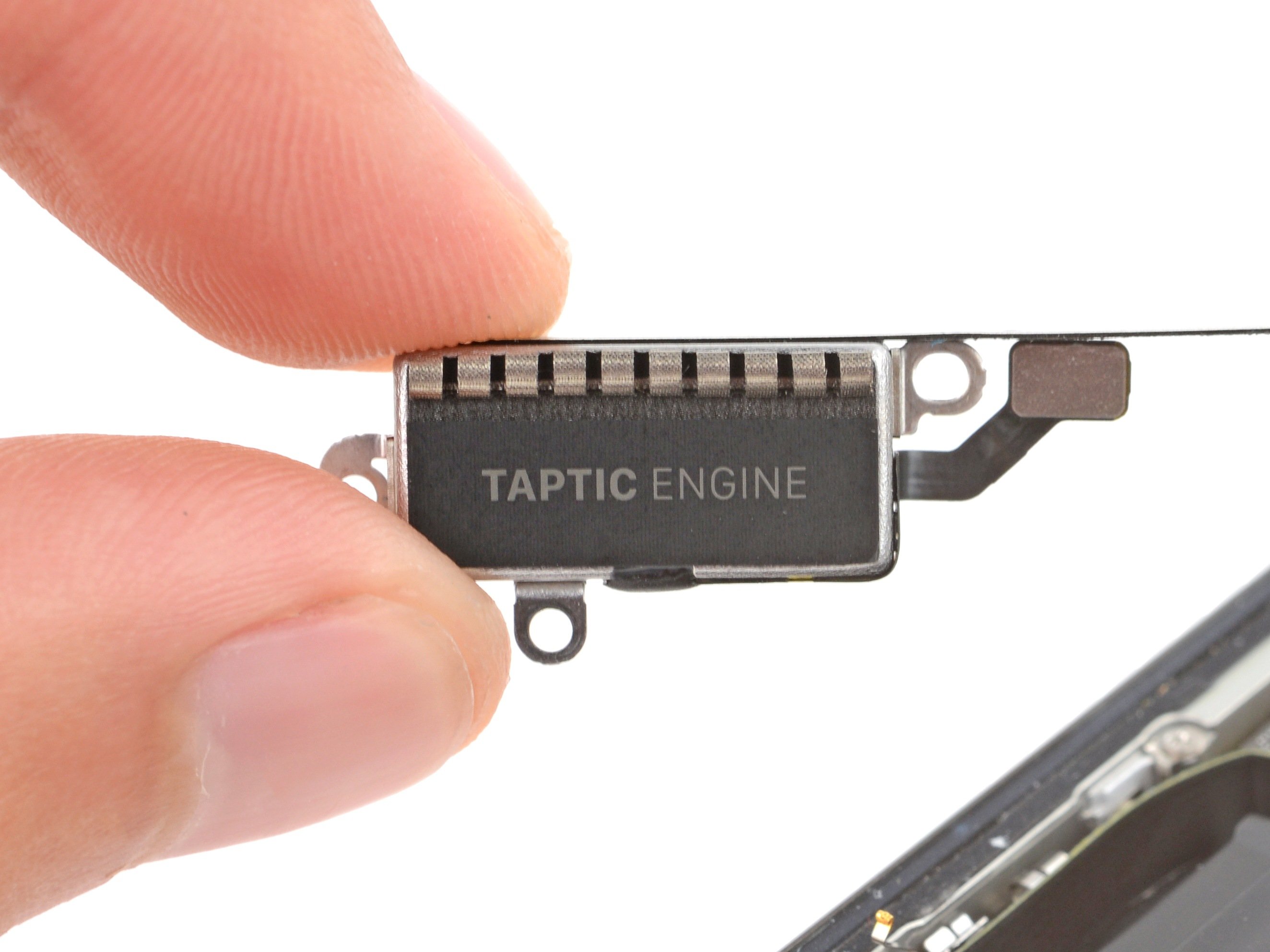
Step 39


Be careful not to pry just on the contact pads! That could break them. Make sure the arm is under the vibration motor body before you pry.
– Gently slide one arm of your trusty angled tweezers beneath the vibration motor and give it a little lift to break free from its sticky adhesive hold.
Tools Used
Step 40


If your vibration motor doesn’t come with adhesive pre-installed, don’t worry! Just give it a little hug with some thin double-sided tape before gently pressing it into place. You got this!
– Now that your device is in one piece again, just retrace your steps to put it back together smoothly!
– Feeling curious? Give the built-in Diagnostic tool a whirl to check everything’s humming along. Click here for a quick dive!
– Got some old gear lying around? Make sure to send it off to an R2 or e-Stewards certified recycler to keep our planet happy.
– Didn’t quite go as planned? No worries! Dive into some basic troubleshooting or swing by our Answers community for friendly support.
– Changed your mind? No hard feelings—just back out and take care!
–
Success!