How To Replace Google Pixel 8a Rear Cameras – DIY Guide
Duration: 45 minutes
Steps: 46 Steps
Great job on trying to fix your device! Just a heads up, this handy guide was whipped up by our cool repair crew here at Salvation Repair, but don’t worry, it’s totally legit. For more info on our step-by-step approach, click here.
Hey there! Ready to tackle the challenge of replacing the wide, ultra-wide, or both rear cameras in your Pixel 8a? Let’s dive in! You’ll be removing both cameras and swapping them out for a shiny new housing, since the adhesive comes pre-installed. If your rear cameras are giving you trouble with focus or stabilization, or if you’ve got a cracked or scratched lens, it’s time for a change! Don’t forget, you’ll also need some replacement adhesives for the back cover and flash unit, along with a new rear camera housing to wrap up the job. Just a heads up: any repair can affect your phone’s water resistance, so how well you reapply that back cover adhesive is key to keeping the water out. If you need help, you can always schedule a repair.
Step 1


Make sure to let your Pixel’s battery dip below 25% before diving into this repair. A lithium-ion battery that’s fully charged could potentially catch fire if it gets damaged, and we definitely want to avoid that!
Hit the power and volume up buttons simultaneously to pop up the shutdown menu.
– Time to kick those cables to the curb! Unplug everything from your phone.
– Now, let’s give your phone a little nap. Make sure it’s completely powered off.
Step 2


– Take a confident poke with a SIM eject tool, small drill bit, or a straightened paper clip into the SIM card tray hole on the left side of your phone until it pops out.
– Slide out the SIM card tray.
Step 3


The back cover is held down with some sticky adhesive all around the edges and close to the cameras. To keep your phone’s insides safe and sound, pay attention to the following:
– Just a friendly reminder: keep your tool within 3 mm of the edges (that’s about the width of the flat part of your opening tool) unless we say otherwise!
– And hey, steer clear of the camera bump edges with your tool; we want to keep that safe and sound!
Step 4


Your opening tool has a flat end and a curved end. Use the flat end, angle it so the tool’s sharp edge points upward, and gently pry open your device! Easy peasy, lemon squeezy!
– Gently slide the edge of your trusty opening tool between the back cover and the frame. For the best results, start with one of those sharp corners – it’s like giving the adhesive a little nudge to help them part ways!
Step 5


– Gently glide your trusty opening tool along the bottom edge to break free the adhesive that’s keeping the back cover snugly in place. You’ve got this!
Step 6


– Swing your opening tool around the bottom right corner and glide it up the right edge, stopping at the bottom of the camera bump.
– Whisk your opening tool out from under the back cover.
Step 7


– Gently slide your trusty opening tool beneath the top right corner of the back cover, right above that little camera bump.
– Now, glide your opening tool along the top edge, and stop at the top left corner, just above where the camera bump hangs out.
– Carefully lift your opening tool away from the back cover, and you’re all set!
Step 8


– Let’s get this party started! Slide your opening tool under the left edge of the back cover, right below the camera bump.
– Now, gently glide your tool down the left edge to separate the adhesive. You’re doing great!
Step 9


There’s a nifty strip of adhesive right above the camera bump that keeps the top edge of the back cover nice and secure.
Feel free to slide your opening pick in more than 3 mm along the top edge—it’s all about that gentle touch!
– Gently slide an opening pick beneath the top left corner of the back cover, making sure the tip nestles close to the top edge of that camera bump.
– Now, with a smooth motion, glide the pick over to the right until you hit the outer edge of the cameras. Easy peasy!
Step 10


One last charm to keep your back cover snug and secure!
– Slide the flat edge of your trusty opening pick under the back cover, right below the camera bump. You’ve got this!
– Now, grab a second opening pick and do the same thing on the opposite side. Teamwork makes the dream work!
Step 11


Handle the back cover with care – we don’t want any unintentional bends here! If the adhesive is being a bit stubborn, try giving the cover a gentle wiggle side-to-side to help it loosen up.
If that adhesive is being stubborn, don’t worry! You can give it a little TLC with a hair dryer or iOpener to help loosen things up. Just gently warm the back cover below the camera bump, and you’ll be good to go.
– Gently lift the back cover using both picks at the same time while keeping constant pressure to break free the last bit of adhesive holding it in place. You’ve got this!
Tools Used


Step 12


– First up, let’s get that back cover off!.
– Now that you’ve got everything apart, let’s take a moment to power your phone back on. Give it a quick test to ensure it’s all good to go before sealing it back up. Once you’ve checked everything, power it down again to continue.
– Ready to wrap it all up? Follow this guide to put on some fresh adhesive and secure that back cover snugly in place. You’ve got this!
Step 13


Just warm up that flash until it’s cozy to the touch. Remember, the battery and nearby parts can be a bit sensitive to heat, so let’s keep it chill!
If you’re feeling adventurous, grab an iOpener or a heat gun to give that flash a little warmth!
– Grab your trusty hair dryer and give that flash unit a little warm-up! This will help loosen the adhesive that’s holding it to the logic board cover. A little heat goes a long way!
Tools Used

Step 14


Hey, be careful not to tear that flash cable! It’s pretty delicate, so treat it like a precious piece of tech. You got this!
– Gently slide your pick underneath the top edge of the flash, giving it a little lift to break free from the adhesive that’s been keeping it cozy with the cover.
– When it’s time to put everything back together, just refer to this guide to make sure you stick that flash down with fresh adhesive like a pro!
Step 15


As you dive into this repair adventure, keep a close eye on each screw and remember to return it to its cozy home once you’re done. No screw left behind!
While the Pixel 8a likes to party with Torx Plus screws, regular Torx bits are ready to join the fun too. Just remember to press down firmly to keep everything in check and avoid any stripping drama.
– Grab your trusty Torx Plus 3IP screwdriver and get ready to tackle those 15 screws holding down the logic board cover:
– You’ll need to unscrew thirteen 4.3 mm-long screws.
– And don’t forget about the two 1.9 mm-long screws!
Step 16


Be extra cautious around the spring contacts lining your phone’s edges. Remember, only use your tool in the designated spots!
– Slide an opening pick underneath the bottom right corner of that logic board cover and gently pry it up to release the sneaky clip.
– Wedge the tip of a spudger into the notch near the top right corner of the logic board cover (just below the screw hole) and give it a little pry to pop that clip loose.
Tools Used

Step 17


– Gently lift the top edge of the logic board cover and guide the flash unit through its cutout like a pro!
– When you’re putting everything back together, remember to thread the flash through its cutout as you lower the logic board cover back into position.
Step 18


– Pop off the logic board cover (yep, it’s the one with the wireless charging coil hooked to it).
Step 19


– Grab a trusty pair of tweezers or just your fingers to gently pop off the metal cover on the right side of your phone.
– When you’re putting it all back together, tuck the upper left corner of the cover under the hook on the logic board first, then lay it down smoothly into place.
Tools Used

Step 20

Heads up! This guide was made using the Verizon version (G8HHN) of the Pixel 8a. It’s got an extra wire and connector for 5G, right next to the battery. If yours doesn’t have the 5G stuff, just skip any steps that mention the antenna cable. No sweat!
Step 21


Watch out for those sneaky surface mounted components and 5G mmWave connectors near the battery! Only pry where it’s safe and let your inner phone surgeon shine!
To reattach that connector, simply line it up with the socket and give a gentle nudge on one side until you hear a satisfying click. Then, work your magic on the other side! It might take a couple of attempts to get everything aligned just right, but don’t sweat it – you’ve got this!
– Gently slide the flat end of your trusty spudger beneath the right edge of the battery press connector, and with a little finesse, pry it straight up to disconnect it. You’ve got this!
Tools Used
Step 22


– Gently slide the tip of a spudger under the lower edge of the 5G mmWave antenna press connector and carefully pry upwards to disconnect it. If you hit a snag, don’t hesitate to schedule a repair for some extra support!
Tools Used
Step 23


– Grab your Torx Plus 3IP screwdriver and carefully unscrew the little 4.3 mm-long screw holding that earpiece speaker snugly in place on the frame. You’ve got this!
Step 24


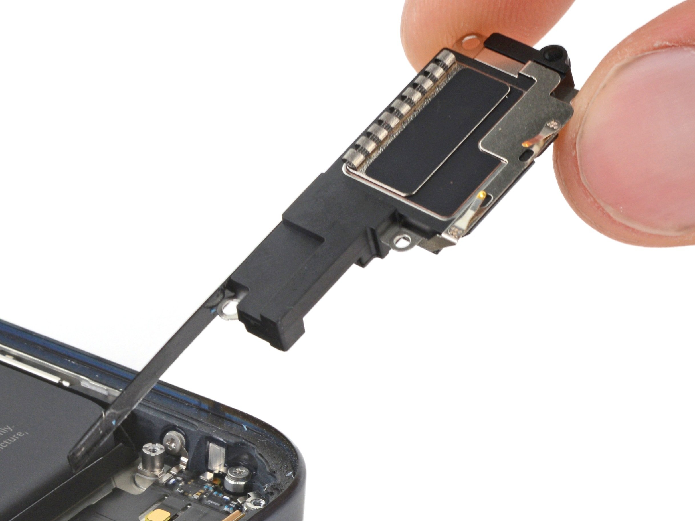
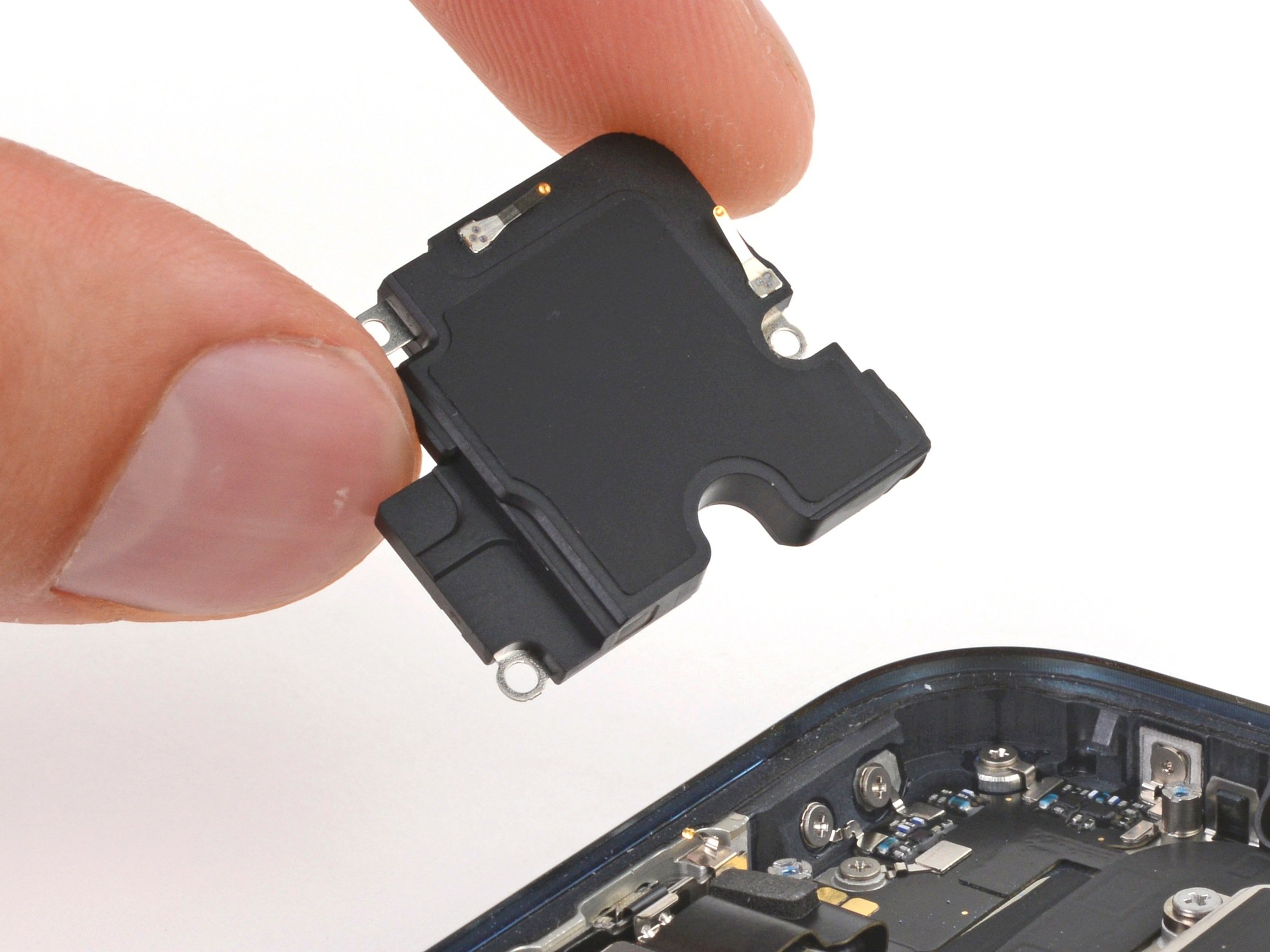
– Gently lift the bottom edge of the earpiece speaker and give it a little wiggle to free it up. You’ve got this!
– When it’s time to pop that speaker back in during reassembly, remember to keep that graphite film out of the way. Insert the speaker at a slight downward angle and nudge it towards the front of your phone so the gasket slides right into its cozy cutout in the frame. Easy peasy!
Step 25


– Grab your trusty Torx Plus 3IP screwdriver and gently take out those two screws that are 4.3mm long, holding the antenna housing in place. Easy peasy!
Step 26


– Slide an opening pick under the left edge of the antenna housing and gently pry it up to pop those clips free.
– Give the top edge a similar treatment to release the last of those tricky clips.
– When it’s time to put things back together, press down firmly around the edge of the housing to snap those clips back in place.
Step 27


– Oh yeah, let’s lift that antenna housing right up and unplug it from its cozy little home. You got this, repair superstar!
Step 28


– Alright, time to put things back together!
– If any of that camera tape is still hanging around on the logic board, grab your tweezers and give it the boot.
– Now, peel that replacement tape off its plastic backing – it’s showtime!
– Carefully place the tape so it connects that metal tab on the bottom right corner of the camera housing to the logic board. You’ve got this!
– Use the flat end of a spudger to give that adhesive a good press, making sure it’s firmly connected to the camera and logic board.
– And finally, peel off the remaining liner. You’re almost there!
Step 29


Hey there, just a quick heads up! You don’t want to mess with those delicate rear camera lenses in the next couple of steps. Be gentle, friend!
– Time to gently nudge that connector loose! Use the tip of a spudger or even your fingernail to carefully pry up and disconnect the press connector right above the battery. Take your time and be gentle, you’re a pro at this!
Tools Used
Step 30


If your trusty pick isn’t sliding under the cable, give that cable a little warm-up with a hair dryer or heat gun to loosen up the adhesive beneath it. You’ve got this!
– Gently slide the tip of your opening pick beneath the right edge of the front-facing camera cable and give it a little lift to pop it off. You’ve got this!
Tools Used
Step 31


– Let’s give those battery and 5G mmWave cables a little nudge out of the way. Nothing too crazy, just enough to make room for our work. You got this!
Step 32


Handle with care and avoid bending the spring contacts on the logic board’s edges. Use your tool exactly as directed.
– Gently slide the tip of your spudger under the little notch at the upper right corner of the logic board and lift it up to pop the board free.
– Now, just like before, do the same on the left side of the board using the notch next to the cameras. You’re doing great!
Tools Used
Step 33


Hey there! The logic board is a sensitive little creature, so handle it with care and be gentle as you ease the lower edge out of the frame.
Hold on before you go all the way! The logic board is still hanging out with the frame via the screen cable, so keep it connected for now.
Before you dive into removing the board, don’t forget to pop out that SIM tray first!
Keep an eye on the flash, front-facing camera, and press connector to ensure they don’t get stuck under the frame.
– Gently lift the top edge of the logic board away from the frame, like you’re freeing a butterfly from a net.
– Now, slide that top edge to the right, giving it a little nudge so it glides over the vibration motor and those pesky frame protrusions.
– While you’re at it, guide the charging port out of its cozy little recess in the frame. It’s like a little surprise waiting to be discovered!
– When it’s time to put everything back together, simply push the logic board toward the bottom of the frame. Give that charging port a gentle press until the bottom edge lines up perfectly with its spot in the frame.
Step 34


Hey, this logic board might be a little loosey-goosey during this step. Keep an eye on it, but be sure to avoid any of the camera lenses or connectors. Don’t worry, it’s all part of the fun!
Now, those thermal pads on the underside of the logic board are pretty sensitive. Try not to touch them, okay? We want to keep that heat flowing just right.
No suction handle? No worries! Just prop up your phone against a sturdy friend, like a heavy box or a thick book.
– Grab a suction handle and stick it to the left side of the screen, making sure the handle is facing down like it’s ready for action!
– Prop that left side of your phone up so it can stand tall and proud.
– Gently tilt the logic board down and lay it flat, making sure to guide that delicate graphite sheet around the cables like a pro!
Tools Used

Step 35


Hey, watch out for that battery! Don’t accidentally poke a hole in it during this step.
When you’re prying up the display bracket, keep one hand over it to catch it if it pops loose. These things can fly!
Be super careful when you’re lifting the bracket. Just a little wiggle with your tweezers is all you need. The board underneath is pretty delicate.
If your display cable bracket is a little bent and doesn’t want to play nice, don’t worry! Just swap it out for a fresh one. It’s like giving it a brand new start.
– Gently use the tip of one arm of your angled tweezers to lift the top edge of the display cable bracket from the center of the logic board. You’ve got this!
– Now, go ahead and take that bracket out.
– When you’re putting it all back together, make sure to hook the bottom edge of the bracket into its slot on the logic board and give the top a nice firm press to snap it back in place. You’re doing great!
Tools Used
Step 36


– Gently slide the flat end of a spudger or your clean fingernail under the top edge of the display cable press connector and lift it straight up to disconnect. You’re doing great!
– This cable can be a bit feisty, so if you find it tricky to reconnect, hold the neck of the cable steady with tweezers. Just line it up over the socket and give it a gentle press down to secure it. You’re almost there!
Step 37


– Carefully lift the logic board out of its cozy little frame. Make sure to be gentle and take your time – it’s like giving it a little hug as you set it free!
Step 38


Keep those fingers and tools away from the sensor!
– If that little rubber gasket for the front sensor decided to hang tight on the frame or is looking a bit out of place, just go ahead and gently pop it off and set it aside for now.
– When it’s time to put everything back together, simply position the gasket over the front sensor on the logic board, making sure the smaller cutout is facing up. You’ve got this!
Step 39


– As you start putting things back together:
– Give those thermal pads a good once-over—they’re hanging out on the underside of the logic board or chilling on the right side of the frame.
– If you’re bringing back your trusty logic board and see that the thermal pads are looking a bit worse for wear, take off the old pad, grab some strong isopropyl alcohol (over 90%) to clean up, and slap on a fresh pad.
– Got a shiny new logic board that came pad-less? No worries, just pop those new thermal pads on now!
Tools Used

Step 40


– Pop your spudger under the long edge of one rear camera press connector and gently lift up to disconnect.
– Do the same with the other rear camera. You’ve got this!
Tools Used
Step 41


– Gently turn the logic board upside down, like flipping a pancake!
– Grab those tweezers and carefully lift off that tiny piece of conductive tape from the right side of the rear camera housing. You’ve got this!
Tools Used
Step 42

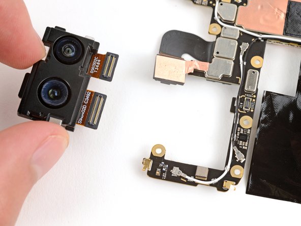
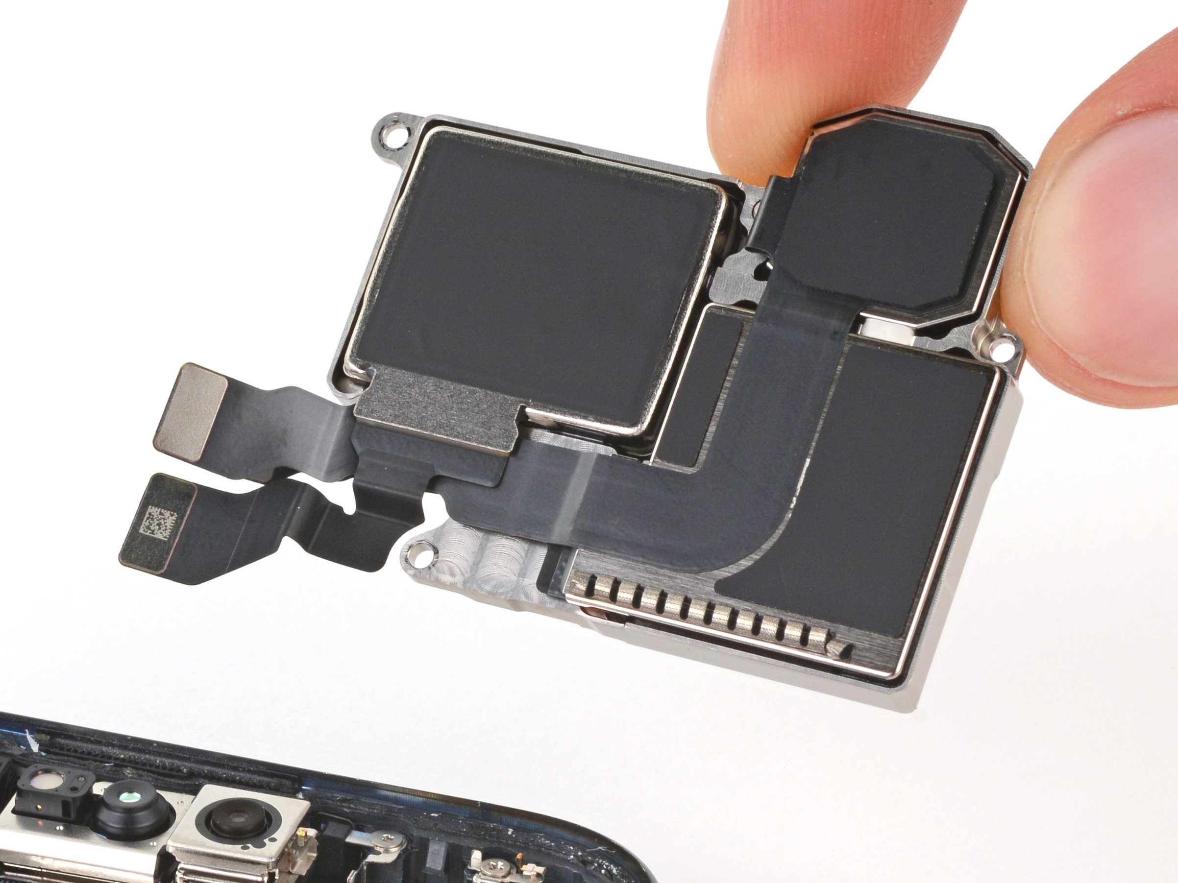
– Gently lift and take out the rear cameras. They’ll be waiting for you to give them some fresh air!
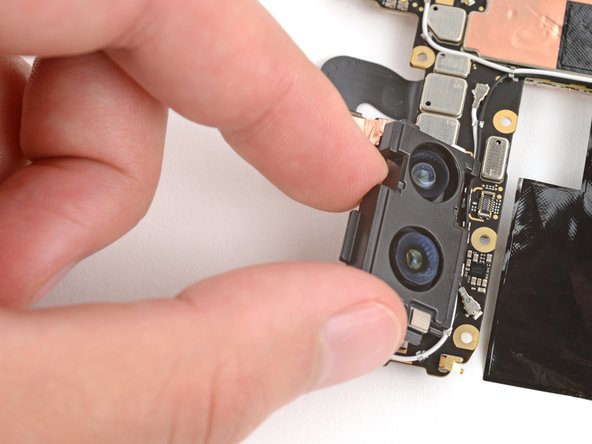
Step 43


Since the rear camera adhesive is already stuck down on your shiny new housing, you’ll want to transfer both of those cameras over like a pro.
– Gently tug at both rear cameras to free them from their snug little homes.
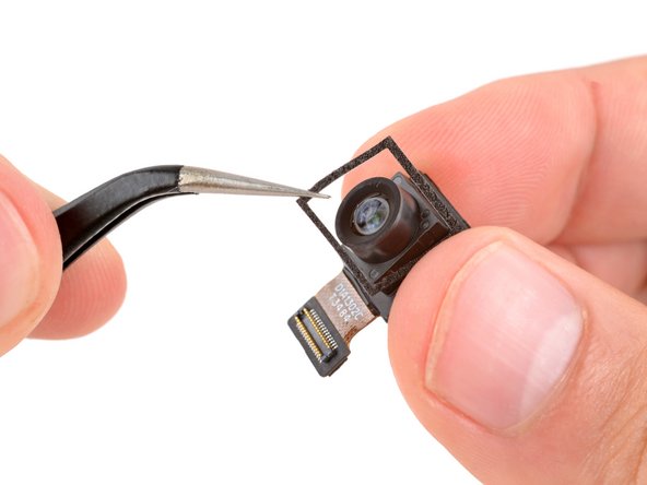

Step 45

– Alright, champ! If your brand new rear camera lens cover is hangin’ around, give it the boot! Take it off, you know what I mean? Get rid of it!
Step 46


– Ready to put your device back together? Just follow these steps in reverse, starting from here.
– Want to check if everything’s working perfectly? Give the built-in diagnostic tool a whirl by clicking here.
– When it’s time to part ways with your old tech, make sure to take it to a certified R2 or e-Stewards recycler.
– If things didn’t quite work out as planned, don’t sweat it! Try some basic troubleshooting, or reach out for a helping hand in our vibrant Answers community.
– Decided to take a rain check? No worries, just cancel this guide whenever you’re ready.
–
Success!