Replace Google Pixel 8a Front Camera: DIY Guide & Tutorial
Duration: 45 minutes
Steps: 41 Steps
This repair guide is brought to you by the wonderful folks at Salvation Repair. It’s a nifty little resource, though it’s not officially backed by any big tech giants. For more info about our repair guides, check us out!
Welcome to your guide for swapping out that front-facing selfie camera on your Pixel 8a! If your selfies are looking a bit fuzzy or your camera has decided to take a permanent vacation, it might be time for a little replacement action. Grab yourself a new front camera, some back cover adhesive, and flash unit adhesives to get started. Just a heads up—any repair could affect your phone’s water resistance, so make sure to stick that back cover down well for the best results. If you ever feel a bit overwhelmed, don’t hesitate to schedule a repair with us!
Step 1


Hey there, before you get started, make sure your Pixel’s battery is at least a quarter full, or less. A charged battery can get a little frisky if it’s damaged during the repair. Just a heads up, so we can all stay safe and happy!
Simultaneously press the power and volume up buttons to unveil the shutdown menu.
– First things first, let’s give your phone a little break! Unplug all those cables.
– Now, it’s time for a power nap! Go ahead and completely turn off your phone.
Step 2


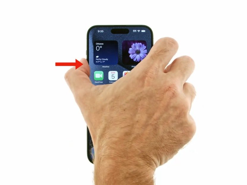
– Get your hands on a SIM eject tool, a handy bit, or even a straightened paper clip, and give that SIM card tray hole on the left side of your phone a firm press until the tray pops out like magic!
– Carefully pull the SIM card tray out and set it aside.
Step 3


The back cover is held tight with some sticky stuff all around the edges and close to the cameras. To keep your phone’s insides safe and sound, check out these tips:
– Alright, champ, let’s keep those tools in check! Unless we say otherwise, don’t go sticking your tool more than 3 mm (about the width of your opening tool’s flat side) around the edges.
– And remember, don’t go poking your tool under those edges of the camera bump. We want to keep things smooth, right?
Step 4


Your opening tool has a flat end and a curved end. Use the flat end and angle it so the tool’s sharp edge points upward. You’ll be a pro in no time!
– Let’s get this party started! Slide the edge of your opening tool between the back cover and the frame. Start at a corner of the tool so you can get a good grip. It’s like a tiny dance to separate the adhesive.
Step 5


– Gently glide your trusty opening tool along the bottom edge to break free the adhesive holding the back cover in place.
Step 6


– Use your opening tool to carefully glide around the bottom right corner and up the right edge, halting just before the camera bump.
– Gently withdraw your opening tool from beneath the back cover.
Step 7


– Wiggle your trusty opening tool under the top right corner of the back cover, right above that camera bump.
– Now, slide your tool along the top edge, bringing it to a gentle stop at the top left corner, just above that camera bump.
– Time to say goodbye! Take your opening tool out from under the back cover.
Step 8


– Gently slip your trusty opening tool under the left side of the back cover, right beneath that camera bump.
– Now, slide that opening tool down the left edge to break free the adhesive. You’re doing great!
Step 9


There’s a little strip of adhesive above the camera bump that holds the top edge of the back cover in place.
You can gently slide the opening pick along the top edge for at least 3mm.
– Slide the opening pick gently into the top left corner of the back cover, aiming for that sweet spot right near the edge of the camera bump.
– Once you’re set, glide the pick to the right, stopping when you hit the right edge of the cameras.
Step 10


One last strip of adhesive is holding the back cover in place down by the camera bump. You’ve got this!
– Gentlyslide the thin edge of an opening pick beneath the back cover, just beneath the camera bump. You’re doing great!
– Now, it’s time for a buddy pick! Insert a second opening pick in the same spot on the opposite side. Keep up the fantastic work!
Step 11


Handle that back cover with care—no bending, please! If the adhesive is being a bit stubborn, gently wiggle the cover side-to-side to help it loosen up. Remember, every little bit helps!
If that stubborn adhesive is holding tight, give the back cover a gentle warming just below the camera bump using a hair dryer or an iOpener to loosen it up.
– Carefully use both picks to lift the back cover while keeping steady pressure to break loose that last stubborn piece of adhesive holding it in place. You’ve got this!
Tools Used


Step 12


– Let’s kick things off by taking off the back cover.
– Now, while we’re putting everything back together:
– Before you seal things up tight, it’s a great moment to give your phone a quick test drive. Power it up and make sure it’s running smoothly. Don’t forget to turn it back off before you dive into reassembly.
– Check out this guide to reapply some fresh adhesive and get that back cover back on nice and snug.
Step 13


Just give the flash a little warm hug – don’t go overboard, you don’t want to scorch it! That battery and its pals are a bit sensitive to heat, so be gentle, okay?
You can also grab an iOpener or a heat gun to gently warm up the flash. Just a little heat goes a long way!
– Grab your trusty hair dryer and give that flash unit a warm hug! A little heat will help loosen up the adhesive that’s holding it tight to the logic board cover. You’re doing great!
Tools Used

Step 14


Handle the flash cable with care, it’s as delicate as a butterfly’s wing!
Step 15


As you dive into this repair journey, don’t forget to keep an eye on those little screws! They like their original homes, so make sure they return to the right spot when you’re done.
The Pixel 8a might sport Torx Plus screws, but don’t sweat it—regular Torx bits do the trick just fine! Just remember to keep that steady downward pressure to avoid any stripping mishaps.
– Grab your trusty Torx Plus 3IP screwdriver and get ready to unscrew! It’s time to liberate the logic board cover by removing 15 screws:
– Thirteen screws that are 4.3 mm long
– Two screws that are 1.9 mm long
Step 16


Handle those spring contacts around your phone’s edge with care—they’re sensitive little guys! Make sure to only insert your tool where we’ve pointed you to.
– Slide an opening pick into the bottom right corner of the logic board cover and gently lift it up to pop that clip free.
– Take the tip of a spudger and work it under the notch just below the screw hole at the top right corner of the logic board cover, then pry it up to unclip it.
Tools Used

Step 17


– Gently lift the top edge of the logic board cover and carefully guide the flash unit through its designated cutout. You’ve got this!
– When it’s time to put everything back together, remember to thread the flash through its cutout as you lower the logic board cover back into position. Easy peasy!
Step 18


– Time to get that logic board cover off! It’s holding onto that wireless charging coil like a best friend, so let’s give it a little nudge and get it out of the way.
Step 19


– Grab a trusty pair of tweezers or just your fingers to gently lift off the metal cover on the right edge of your phone.
– As you put things back together, be sure to tuck the upper left corner of the cover under the hook on the logic board before settling it into place.
Tools Used

Step 20

This guide was originally made for the Verizon model (G8HHN) Google Pixel 8a, which had an extra cable and connector for the 5G mmWave antenna (just to the left of the battery connector). If you have the non-mmWave model, you can always skip any steps that mention the antenna cable! If you need help, you can always schedule a repair.
Step 21


Be super careful not to mess up those delicate surface-mounted components near the battery and 5G mmWave connectors—only pry where we tell you to!
To reconnect a press connector, line it up over the socket and give it a gentle push on one side until you hear a satisfying click. Then, do the same on the other side. It might take a couple of tries to get it lined up just right. You got this!
– Gently slide the flat edge of your trusty spudger under the right side of the battery press connector and give it a little nudge straight upwards to disconnect it. Easy peasy!
Tools Used


Step 23


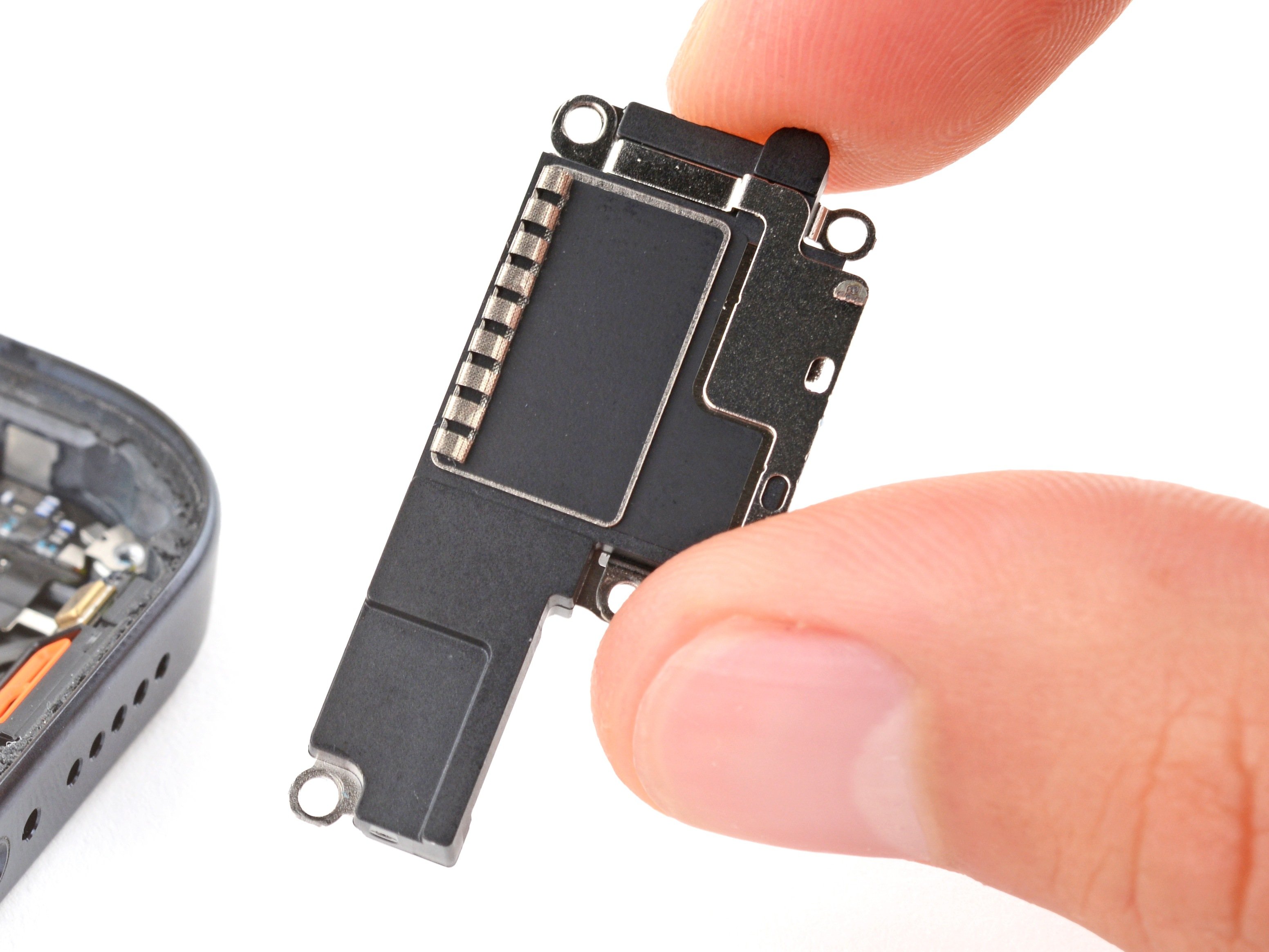
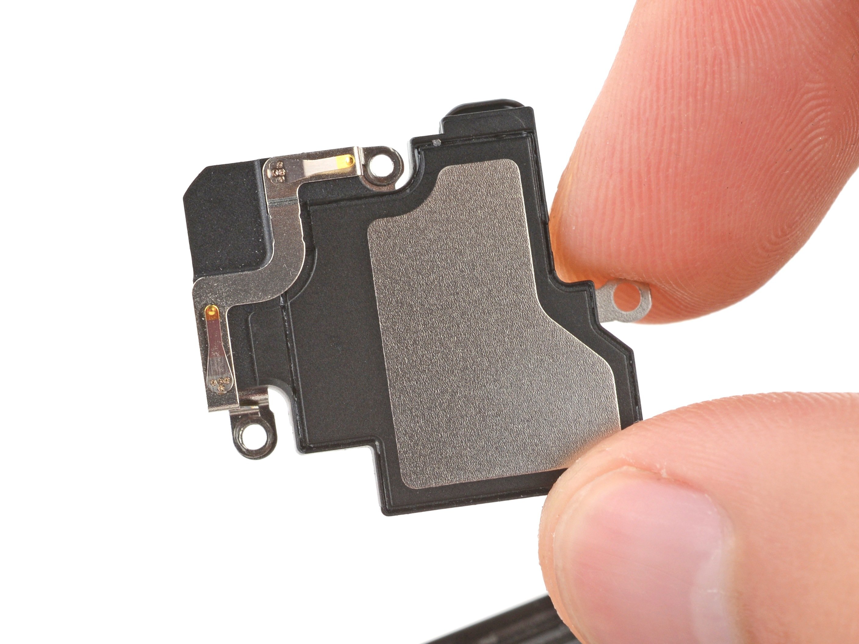
– Grab your trusty Torx Plus 3IP screwdriver and get ready to work some magic! Remove the 4.3 mm-long screw that’s keeping the earpiece speaker snugly attached to the frame. You’ve got this!
Step 24


– Let’s get this earpiece speaker out of there! Gently lift the bottom edge of the speaker and give it a little wiggle. It should come right off.
– Now, when you’re putting it back in, make sure that little graphite film isn’t getting in the way. Then, give the speaker a little tilt (like you’re saying ‘hi’ to the front of the phone) and gently push it in. The gasket should snuggle right into its place in the frame.
Step 25


– Grab your trusty Torx Plus 3IP screwdriver and gently unscrew those two 4.3 mm-long screws holding down the antenna housing. You’re doing great!
Step 26


– Slide an opening pick beneath the left edge of the antenna housing and give it a gentle nudge upwards to pop those pesky clips loose.
– Now, let’s do a little repeat performance on the top edge to free the last of those clips.
– When you’re putting it all back together, make sure to press around the edges of the housing with a bit of gusto to lock those clips in place!
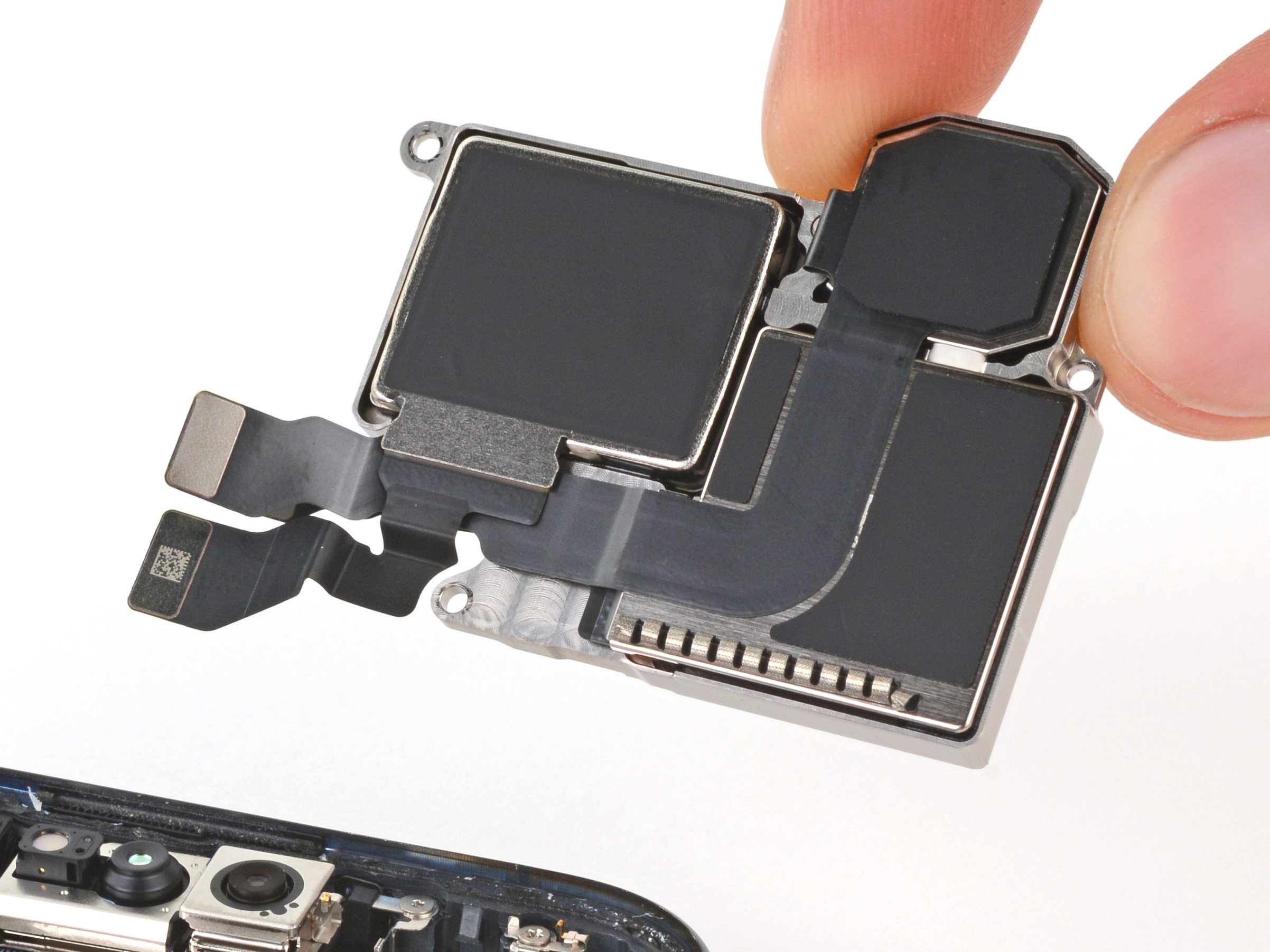
Step 27


– Give that antenna housing a little lift and send it packing!
Step 28


– As you gear up for reassembly, let’s get that front-facing camera sorted! First things first, if there’s any pesky copper tape lingering on the logic board, grab your tweezers and gently pull it off.
– Next, give the front-facing camera a little nudge with your finger to settle it nicely into its cozy spot.
– Now it’s time to reveal the magic! Peel off the larger, clear liner from the front-facing camera copper tape to unveil the sticky goodness.
– Carefully lay the copper tape over the camera, making sure the skinny end points down towards the bottom of the phone. It’s like a little hat for your camera!
– Using the flat end of a spudger, press down firmly on the adhesive to secure it snugly against the camera and the logic board. We want it to stick like a champion!
– Finally, go ahead and peel off the last two liners from the copper tape. Your work is almost done!
Step 29


Be mindful of the rear camera lenses as you proceed with the next couple of steps, my tech-savvy friend! 😉✨
– Gently nudge up the press connector located just above the battery using the tip of a spudger or your trusty fingernail. You got this!
Tools Used
Step 30


– Now, take your opening pick and slide the tip under the right edge of the front-facing camera cable. Gently lift to disconnect it. It’s like giving the cable a little high five!
Tools Used
Step 31


– Gently set the battery and those 5G mmWave cables aside so they don’t get in the way while you’re working your magic.
Step 32


Handle those delicate spring contacts on the edges of the logic board with care – they’re super sensitive! Make sure to only insert your tool exactly where we tell you to.
– Gently slide the tip of your spudger beneath the notch at the top right corner of the logic board, and give it a little nudge to unclip that board like a pro.
– Now, let’s do a little repeat action on the other side! Use the notch to the left of the cameras to unclip that side too. You’re almost there!
Tools Used
Step 33


Hey there! Just a heads up, the logic board is a bit of a diva. So, handle it with care and avoid bending it while you’re gently freeing the lower edge from the frame.
Hold your horses! Don’t yank the logic board out just yet; it’s still hanging out with the frame thanks to the screen cable.
Before you dive into removing the board, double-check that you’ve taken out the SIM tray first.
Make sure the flash, front-facing camera, and press connector don’t get stuck under the frame.
– Gently lift the top edge of the logic board away from the frame, like raising a sleepy cat.
– Carefully pull the top edge of the logic board to the right so those little cutouts can glide over the vibration motor and any frame bumps.
– As you’re pulling, be sure to guide the charging port out from its cozy spot in the frame.
– When it’s time to put everything back together, nudge the logic board down toward the bottom of the frame and press the charging port until the bottom edge is snug with its frame buddy.
Step 34


Hey there! Just a heads up, the logic board might decide to do a little dance during this step. Keep it steady, but remember—no gripping those camera lenses or connectors, okay?
Also, steer clear of the thermal pads on the back of the logic board. They like their personal space!
If you don’t have a suction handle, don’t worry! Just find a sturdy object like a heavy box or a thick book and use it to prop up your phone. You got this!
– Attach a suction handle to the left side of the screen with the handle facing downward.
– Stand your phone upright by propping up the left side.
– Tilt the logic board down flat, and carefully guide the delicate graphite sheet around the cables.
Tools Used

Step 35


Let’s tread carefully and avoid poking that battery! We don’t want any surprise fireworks.
Keep one hand above the display bracket while you pry it up—just in case it decides to make a dramatic exit.
Watch out for the board hiding under the bracket’s socket! Just nudge your tweezers in enough to lift the bracket, no need for a wrestling match here.
If your display cable bracket is a little bent and just won’t fit, it’s time to swap it out for a shiny new one!
– Gently use the pointy end of one arm of your angled tweezers to lift the top edge of the display cable bracket right from the center of the logic board. Easy peasy!
– Now it’s time to say goodbye to that bracket—just take it out.
– When you’re putting everything back together, remember to hook the bottom edge of the bracket into its cozy little slot on the logic board and give the top a good press down to snap it back in place. You’ve got this!
Tools Used
Step 36


– Gently wiggle the flat end of a spudger or a clean fingernail under the top edge of the display cable press connector and pop it up to disconnect. It’s like opening a treasure chest—just less swashbuckling.
– Reconnecting this cable can be a bit of a dance. If it feels tricky, grab some tweezers and guide the neck of the cable into place. Align it over the socket and give it a firm press to secure.
Step 37


– Time to give that logic board a little break! Carefully remove it from the frame. It’s like giving it a mini-vacation.
Step 38


Hands off the sensor, folks! Keep those fingers and tools away.
– If that front sensor rubber gasket decided to stick around on the frame or got a bit out of whack, just pop it off and put it aside for now.
– When it’s time to put everything back together, make sure to position the gasket over the front sensor on the logic board, with the little cutout facing up.
Step 39


– Time to put it all back together! First things first: take a peek at those thermal pads. They hang out on the underside of the logic board or chill in the right corner of the frame.
– If you’re reusing your old logic board and those thermal pads are looking worse for wear, don’t sweat it! Just peel off the old one, give the surface a good scrub with some high-powered isopropyl alcohol (we’re talking over 90% here!), and stick on a fresh pad.
– Got a shiny new logic board? Sweet! If it didn’t come with thermal pads already attached, now’s your chance to add them on before sealing everything up.
Tools Used


Step 41


– Gently flip the logic board over with care.
– Lift the front camera softly to peel away the copper tape attaching it to the logic board.
– Take out the front camera.
– If your new front-facing camera has a lens cover, be sure to remove it.
Success!