DIY Google Pixel 5a Motherboard Replacement Guide: Step-by-Step
Duration: 45 minutes
Steps: 38 Steps
Hey there, this repair guide was made by the awesome folks at iFixit, but remember, Google isn’t involved.
Safety first! Let’s keep things chill and discharge your battery down to 25% or less before getting hands-on. You got this! If you need a helping hand, you can always schedule a repair.
The team at Salvation Repair put together this guide to help you replace the motherboard on your Google Pixel 5a. If your charging port is on the fritz, you might need to swap out the whole motherboard since they’re soldered together. Before you start, make sure your battery is at 25% or less to minimize the risk of a fire if it gets damaged. And if your battery is looking a little puffy, take some extra precautions. Follow these steps and you’ll be back up and running in no time. If you need help, you can always schedule a repair.
Step 1


A standard SIM card eject tool might be too wide for this little guy. Don’t force it! Use a small paperclip or a tool made for the job, like the SIM eject bit.
– Grab your trusty SIM card eject tool and gently slide it into the tiny hole on the right edge of the frame.
– Give it a firm push until you hear that satisfying pop of the SIM card tray coming loose.
– Now, carefully pull out the SIM card tray from your phone and you’re on your way!
Step 2


First things first, let’s make sure your device is off before diving into the repair adventure!
Next up, you’ll want to gently pry the screen away to free it from the phone. Take a moment to read the following notes carefully before you get started!
Step 3

Depending on how sticky your device is, you might need to warm it up a few times to loosen things up.
– Gather ’round, tech enthusiasts! It’s time to heat up your iOpener and prepare to sweep away those stubborn glues. With a minute of heating magic, we’ll soften those bonds and set the stage for an epic gadget revival! If you need a helping hand, remember that you can always schedule a repair with our amazing team!
Tools Used

Step 4


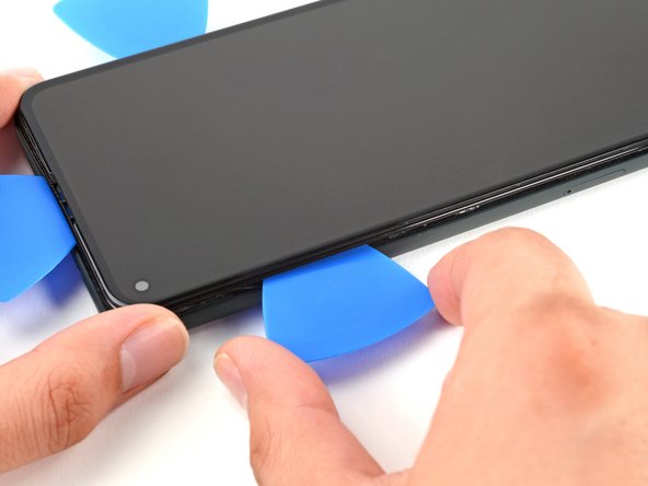
Time to free that screen! Gently slide some opening picks between the black clips holding the bezel to the midframe. You’ll be seeing your phone’s innards in no time! If you need help, you can always schedule a repair
– Check out the best spots to dive in before you get started!
Step 5


If your screen is badly cracked, don’t worry – we’ve got a few tricks up our sleeve. Try covering it with clear packing tape to help the suction cup stick. If that doesn’t work, super strong tape can be a great alternative. And if all else fails, a little superglue can be just what you need to get the job done. Remember, if you need help, you can always schedule a repair
– Grab a suction cup and place it as close to the right edge of the screen as you can. You’re doing great!
– Now, give that suction cup a solid lift with a steady force until you see a tiny gap between the bezel and midframe. Keep it up!
Step 6


The bezel is attached to the midframe using plastic clips. To detach them, simply insert an opening pick along the seam at the designated points. If you need help, you can always schedule a repair
– Carefully slide the tip of your opening pick into the bezel seam, aiming for about 4-5 cm from the bottom of your phone.
Step 7


– Gently slide the tip of your trusty opening pick into the bezel seam, about 3-4 cm from the top of your phone. You’re on your way to a successful repair!
Step 8


If you’re finding this step a bit tricky, just slide that pick along the top right corner of your phone until you’ve created a nice little gap at the top for the opening pick to slip in.
– Let’s get this party started! Gently slide the tip of your opening pick into the seam between the bezel and the top of your phone. It’s like giving your phone a little tickle!
Step 9


If you’re finding this step a bit tricky, try sliding that pick along the bottom right corner of the phone until you’ve created enough space at the bottom to slip in the opening pick. You’ve got this!
– Let’s get started by inserting the tip of an opening pick into the bezel seam at the bottom of the phone. Take your time and make sure it’s securely in place.
Step 10


– Gently slide the tip of your trusty opening pick into the bezel seam on the left side of the phone, about 2 cm from the bottom. You’re doing great!
Step 11

– Gently slide the tip of an opening pick into the bezel seam, positioning it about 3-4 cm below the front-facing camera. You got this!
Step 12


– Hey there, buddy! Wanna try something fun? First, let’s carefully detach all those little clips. If we find any stubborn glue, use that cool opening pick of yours to slice right through! Once we’ve freed the device, yank it open like you’re reading a bedtime story instead of a repair manual. If you need some extra help, you know what to do – just schedule a repair and let us do some magical fixing together!
Step 13

Stay organized during this repair by keeping track of each screw and making sure it ends up back in its original spot. If you need help, you can always schedule a repair
– Let’s get started! Use a T3 Torx driver to carefully remove the 4.6mm-long screw that’s holding the screen connector bracket in place. If you need help, you can always schedule a repair


Step 15


– Use the tip of a spudger to gently pry up and disconnect the screen flex cable. It’s like giving the cable a little high-five to say goodbye!
– To re-attach those press connectors, carefully align and press down on one side until you hear a satisfying click. Then, do the same on the other side. Don’t press down on the middle, though! You want to avoid any accidental pin-bending, which could lead to a not-so-happy device. If you need help, you can always schedule a repair.
Tools Used

Step 16

Don’t forget to snap that screen connector bracket back into place!
– Pop that screen right off the phone!
– When putting things back together:
– If you swapped out the screen, double-check the front-facing camera hole and remove any protective covers.
– Using custom-cut adhesive? Follow this guide to get the new screen adhesive right.
– Using Tesa tape? This guide has you covered.
– During boot-up after reassembly, the screen will calibrate itself. Avoid touching the screen to ensure proper touch calibration and avoid touch issues.
Step 17

– Grab your trusty T3 Torx driver and get ready to remove six screws that hold the midframe in place on the motherboard – it’s time to get this repair started!
– Keep in mind that some of these screws are different lengths, so make sure to keep track of each one and put them back where they belong to avoid any mix-ups.
– Four of these screws are 4.6 mm, so set those aside for now.
– There’s also one 4.0 mm screw to keep an eye on.
– And don’t forget the tiny 2.0 mm screw – it may be small, but it’s an important one! If you need help, you can always schedule a repair


Step 20


– Grab your trusty tweezers and gently lift the tape that’s hiding those two sneaky screws holding down the charging port bracket. You’ve got this!
Tools Used
Step 21

– Let’s get those last few screws out of the way! Use a T3 Torx driver to remove the remaining four screws holding the midframe to the motherboard:
– You’ll find three 4.6 mm screws and one 4.0 mm screw. Easy peasy!
Step 22

Alright, let’s be careful with that battery! Don’t go poking or bending it with your tool, okay? A little mishap could lead to some not-so-nice chemicals or maybe even a fire. We don’t want that! If you need help, you can always schedule a repair.
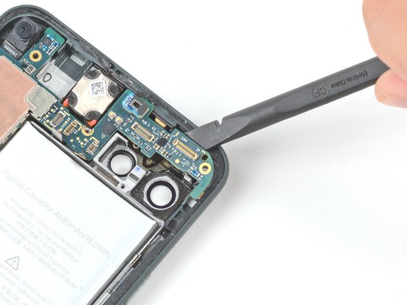
– Time to show that charging port bracket who’s boss! Use a spudger or tweezers to gently peel back the tape holding it to the speaker assembly. It’s like giving it a little high five, but with tools.
Step 23


Heads up! Make sure not to poke or damage the battery when you’re holding the graphite sheet. If you need help, you can always schedule a repair.
– Hey, buddy! Just gently slide that graphite sheet away from your battery using a gentle touch or those trusty tweezers. If you need help, you can always schedule a repair!
Tools Used
Step 24


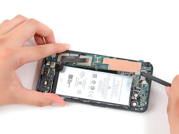
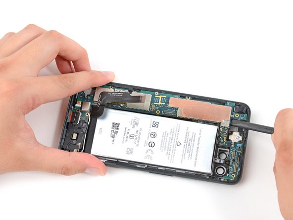
– Let’s get started! Gently slide the pointed end of your spudger under the top right corner of the midframe.
– Now, there’s a sneaky little black plastic clip hanging out at the top of the midframe, keeping it snug. To say goodbye to it, use your spudger to pull the midframe down a bit and then give it a little pry upwards. You got this!
Tools Used
Step 25


– Alright, let’s get that midframe out! Just give it a gentle lift and it should come right off.
Step 26


– There are a couple of small plastic bits that keep the midframe in place. Be careful not to lose them, as they can easily go missing without the midframe to hold them.
– Remember to place them back in their corners before reassembling your device and replacing the midframe. If you need help, you can always schedule a repair.
Step 27


– Time to disconnect the battery! Use the flat end of a spudger to carefully pry up on the battery connector – it’s like a little wake-up call for your device. If you need help, you can always schedule a repair
Tools Used


Step 30

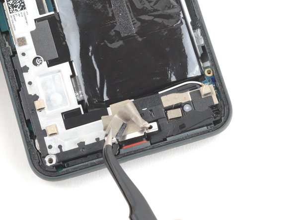
– Gently use the pointed end of a spudger to lift the headphone jack connector and give it a little nudge to disconnect. You’ve got this!
Tools Used
Step 31

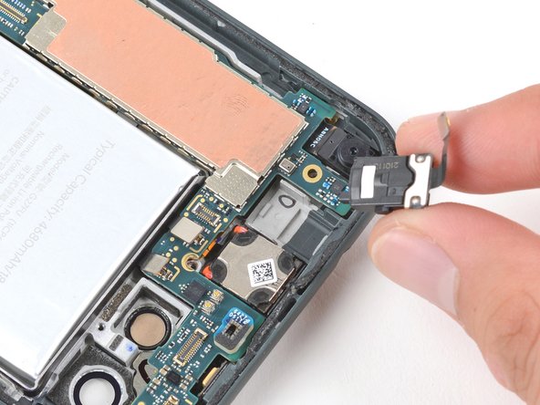
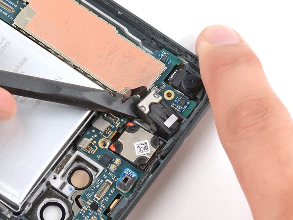
– Grab your trusty spudger and gently nudge the headphone out of its cozy socket. It’s like giving it a little hug goodbye!
– Now, it’s time to say farewell to the headphone jack. Just lift it out and you’re one step closer to your repair victory!
Tools Used
Step 32
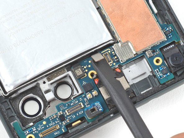

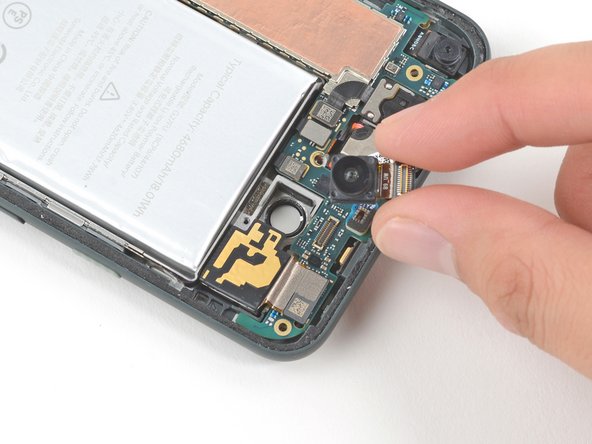
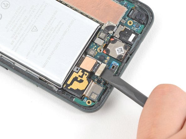
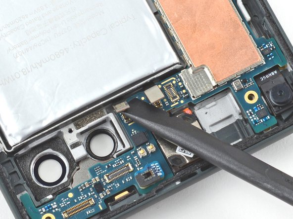
– Now, grab your trusty spudger and use the flat end to gently lift up the fingerprint sensor connector. We’re just disconnecting it, so don’t go crazy! If you’re feeling a little unsure, you can always schedule a repair.
Tools Used

Step 34

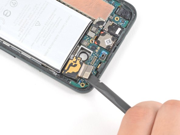
– Let’s get started by using a T3 Torx driver to remove the three 2.9 mm screws that hold the motherboard in place. If you need help, you can always schedule a repair
Step 35

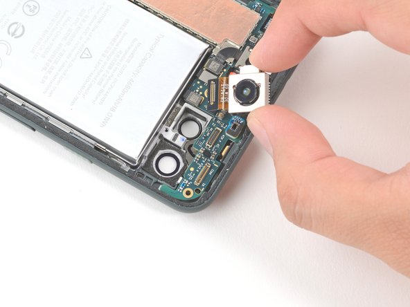
Before you start, make sure you’ve removed the SIM card tray – it’s also what keeps the motherboard in place, so double-check that it’s out to avoid any issues. If you need help, you can always schedule a repair
– Let’s give that motherboard a little lift! Gently slide the flat end of your spudger under the top right corner of the motherboard and give it a little nudge. You’ve got this!
Tools Used
Step 36
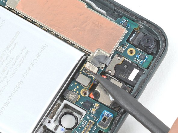
– Now it’s time to gently pry the motherboard loose – insert the flat end of a spudger under the top left corner and carefully lift it away from the frame. If you need help, you can always schedule a repair
Tools Used
Step 37
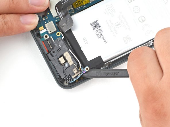

Whoa there, cowboy! Be super gentle when peeling back the speaker cover so you don’t bend that delicate battery. It’s like handling a delicate flower, just happier! 💪😄 If you need help, you can always schedule a repair!
– Gently slide the sharp end of a spudger beneath the screw slot located at the top right of the speaker assembly to carefully pop it loose from the frame.
Tools Used
Step 38

– Gently detach the motherboard along with the speaker assembly. Take your time; they’re just waiting to be set free!