Google Pixel 4 Flash Assembly Replacement Guide: DIY Step-by-Step
Duration: 45 minutes
Steps: 26 Steps
This handy guide was put together by the awesome folks at Salvation Repair, and while we love to help, we’re not endorsed by Google.
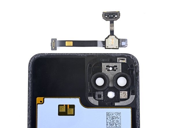
Components involved: LED flash module, spectral and flicker sensor, and back panel microphone.
Heads up!
Just a reminder:
Hey there, tech enthusiast! This clear and easy to follow repair guide will help you swap out the flash assembly in your Google Pixel 4. It’s a little bit of a journey, but we’ve got you covered. This guide is designed to make things a breeze, but remember, we’re not Google. We’re just your friendly neighborhood repair crew at Salvation Repair. This assembly packs a punch with its LED flash module, spectral and flicker sensor, and back panel microphone, so you can capture those awesome pics and videos. Just a heads-up: The microphone section is tucked away with an adhesive gasket, and pulling out the flash module might leave your Pixel a bit vulnerable to water damage. But fear not! We’ll walk you through it step by step. Now, let’s get down to the nitty-gritty. There’s a special insulating/heat-dissipating graphite adhesive layer keeping the flash module snug on the back panel. You’ll need to give it a little TLC to remove it, and make sure to replace it when you’re done. And one more thing: Google advises that disassembling the front laser assembly can be a bit of a hazard with invisible infrared laser emissions. Check out their safety warnings schedule a repair if you’re feeling a little unsure. Alright, ready to rock and roll? Let’s get this repair started! If you need help, you can always schedule a repair.
Step 1
– Grab your trusty SIM eject tool, a bit, or even a straightened paper clip, and gently slide it into the tiny hole on the SIM card tray located on the left edge of your phone.
– Give it a firm press to pop that tray out like a champ.
– Now, go ahead and pull out the SIM card tray with ease.
Step 2
Feeling a little warm under the collar? You can use a hair dryer, heat gun, or hot plate to give your phone a little TLC. But don’t get too carried away, because overheating can be a real buzzkill for your phone’s display and battery. If you need help, you can always schedule a repair
– Get your trusty iOpener nice and warm, and press it against the bottom edge of the back panel for about a minute. You got this!
Tools Used
Step 3
If your back glass is badly cracked, don’t worry – we’ve got you covered. Try slapping a layer of clear packing tape over it, and the suction cup should stick just fine. If that doesn’t work, you can use some seriously strong tape as a substitute. And if all else fails, a tiny bit of superglue can help the suction cup stick to the broken panel. If you need help, you can always schedule a repair
– Grab a suction cup and gently press it onto the warm edge of the back panel. Make sure to push down firmly to create a good seal, getting as close to the edge as you can. You’re doing great!
Step 4
If your phone is older, this might be tricky. If you’re stuck, try giving the edge a bit more heat and give it another go! If you need help, you can always schedule a repair
– Grab that suction cup and give it a good, strong pull! You’re gonna create a tiny opening between the back panel and the frame. No need to be shy!
– Now, take your opening pick and slide it into that gap you just made. We’re getting closer to fixing this!
Step 5
– Gently glide the opening pick along the bottom edge, heading towards the left corner to cut through that sticky adhesive.
– With the pick still snug in place, slide it from the bottom left corner all the way to the bottom right corner to fully slice through the adhesive on the bottom.
– Keep that pick right where it is in the bottom right corner to stop the adhesive from sealing back up.
Step 6
– Grab your trusty iOpener and give it a warm hug on the left edge of your phone for a solid minute. It’s like a cozy blanket for your device!
Tools Used
Step 7
– Let’s get this party started! Insert a second opening pick underneath the back panel right over the charge port.
– Now slide that opening pick down to the bottom left corner of the phone. We’re almost there!
Step 8
That sticky stuff can be a real pain! Don’t worry, just gently push and pull the pick back and forth like you’re sawing through butter. You’ll get through it in no time.
– Gently glide the opening pick around the bottom left corner and along the left side of your phone to cut through that sticky adhesive.
– Pause when you hit the top left corner, close to the camera, and keep that pick in place.
Step 9
– Grab an iOpener and cozy it up to the right edge of your phone for a chill minute. If you need help, you can always schedule a repair.
Tools Used
Step 10
– Now that you’ve got two opening picks in place, it’s time to bring in the third pick to help with the lower part of the right side.
– Gently slide the opening pick upwards, working your way along the right side to break through the adhesive.
– Keep going until you reach the top right corner, then stop and leave that pick right where it is. If you need help, you can always schedule a repair
Step 11
– Now, let’s get that top right corner loosened up! Slide your opening pick around the corner and across the top side of the phone. You’ll be slicing through the last bit of adhesive like a boss!
Step 12
– After you’ve made your way around the phone’s edge, gently lift the right side of the back cover as if you’re opening a book. It’s a delicate dance, so take your time!
– Hold your horses! Don’t yank the panel off just yet; it’s still holding hands with the phone.
Step 13
– Keep swingin’ that back panel open until it’s chillin’ on the left edge of your phone. Just be careful not to stress out that ribbon cable, it’s got a big job to do!
– Now, this is the perfect time to power up your phone and make sure everything is groovin’ before you seal things back up. Don’t forget to power it back down completely before you keep working. You got this!
Step 14
It’s a good idea to keep track of your screws as you go, like a little screw party. Make sure each screw goes back to its original home. It’s like finding the right shoe for each foot, but with screws! If you need help, you can always schedule a repair
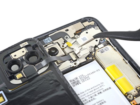
– Let’s get started by removing the five T3 Torx screws that hold the battery connector shield in place:
– You’ll need to take out four 4.0 mm screws
– And one 2.1 mm screw – don’t worry, it’s an easy step! If you need help, you can always schedule a repair
Step 16
Alright, pal, when you’re using the spudger near the battery, be extra careful not to poke a hole in it. We don’t want any unexpected fireworks, ya know? If you need help, you can always schedule a repair.
– Use the pointy end of a spudger to gently pop the battery connector straight up from the motherboard. Battery disconnected!
– To re-attach press connectors like this one, carefully align it and press down on one side until it clicks into place, then do the same on the other side. Avoid pressing down in the middle. Misalignment can bend the pins, causing permanent damage.
Tools Used
Step 18
– Let’s get started! Use a T3 Torx driver to remove the two 4mm screws that hold the back panel connector cover in place. If you need help, you can always schedule a repair
Step 22
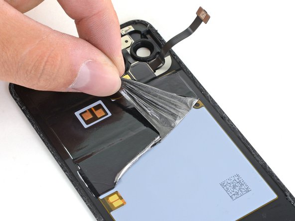
The LED flash module is snugly attached to the back panel, hiding beneath a layer of graphite adhesive that you’ll need to peel away. No worries, you’ve got this!
– Hey there! Want to try something super fun and maybe learn a new skill? Check this out – use those cool tweezers to life up just a tiny bit of the bottom corner adhesive. Then, you can give it a gentle tug with your fingers! If you need a little help, no worries, you can always schedule a repair and we’ll be there in a jiffy!
Tools Used
Step 23
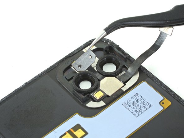
– Time to get started! Carefully peel back the graphite adhesive layer to reveal the wireless charging coil, NFC pads, and LED flash module.
– Now, completely remove the graphite adhesive layer – you’re making great progress! If you need help, you can always schedule a repair
Step 25
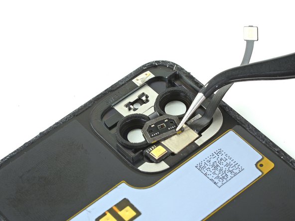
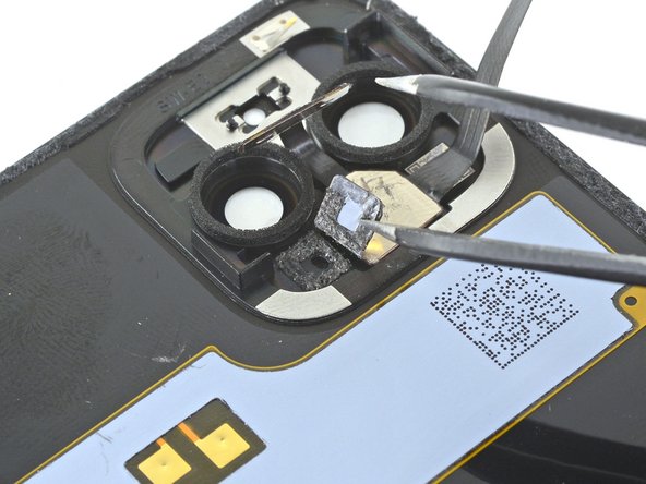
– Grab some tweezers or the sharp end of a spudger to gently lift the microphone off the back panel.
– Before popping in that new LED flash module, give a quick look at the microphone’s adhesive gasket:
– If it looks good as new, feel free to reuse the gasket. Just double-check that it’s not blocking any holes.
– If the gasket seems a bit out of whack, simply remove it and swap in some new adhesive using a pre-cut strip or Tesa tape.
Step 26
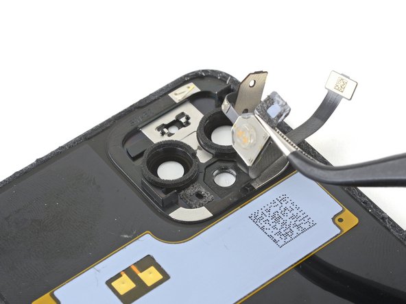
– Let’s get that LED flash housing out of its spot on the back panel. Easy peasy!
– Now, just gently remove that flash module. You got this!


