Google Pixel 3a Daughterboard Replacement Guide – DIY Repair Tutorial
Duration: 45 minutes
Steps: 24 Steps
Hey there! This repair guide was written by the Salvation Repair team, but it hasn’t been checked out by Google. If you want to learn more about our repair guides, you can find them right here.
The Pixel 3a’s display is a bit delicate, so be careful with it. Don’t worry though, we’ll walk you through it step-by-step.
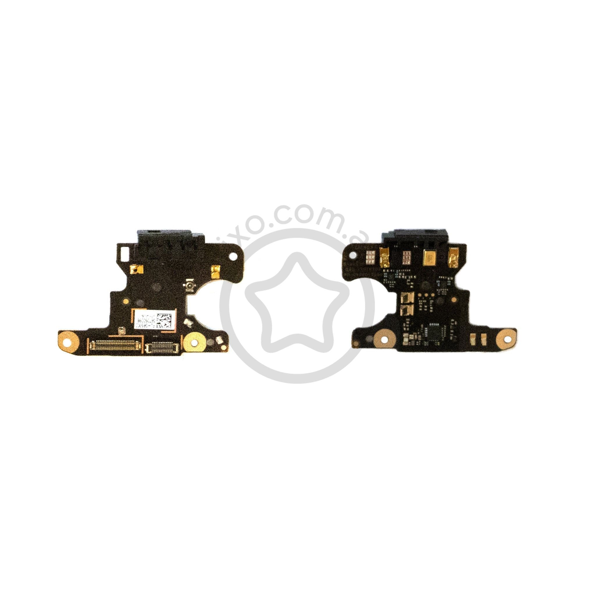
This awesome repair guide is brought to you by the team at Salvation Repair. While Google hasn’t given us a thumbs up, we’re here to help you out! Dive into this guide to swap out the Pixel 3a’s petite daughterboard. This little board is home to the bottom microphone and connects various components like the speaker and the vibration motor. Just a heads up, the Pixel 3a’s display is a bit delicate, so if you’re reusing it, be extra careful with the opening procedure warnings. The most challenging part? Reconnecting the proximity sensor connector—trust us, it takes a bit of patience and a gentle touch. If you need help, you can always schedule a repair.
Step 1


– Keep an eye on those two seams on your phone:
– Before you dive into prying, check out these key spots on the screen:
– Screen seam: This is the line that separates the screen from the rest of the phone. This is your go-to spot for prying.
– Frame seam: This is where the plastic frame meets the back cover. It’s held tight with screws, so let’s not pry here.
– Screen flex cable: Remember, don’t pry deeper than we guide you, or you might end up damaging this cable.
– Adhesive perimeter: Stay within the narrow perimeter while prying, and make sure to angle your pick. Going beyond that could hurt the display panel.
Step 2

You can skip this step if you’re feeling bold! The Pixel 3a’s screen adhesive isn’t super strong, but heating it up will make it a little easier to work with and give your screen the best chance of staying crack-free. If you need help, you can always schedule a repair.
– Let’s get that display warm! Grab your iOpener and give the right edge of the display a nice, hot minute. You got this!
Tools Used

Step 3


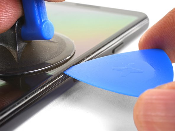
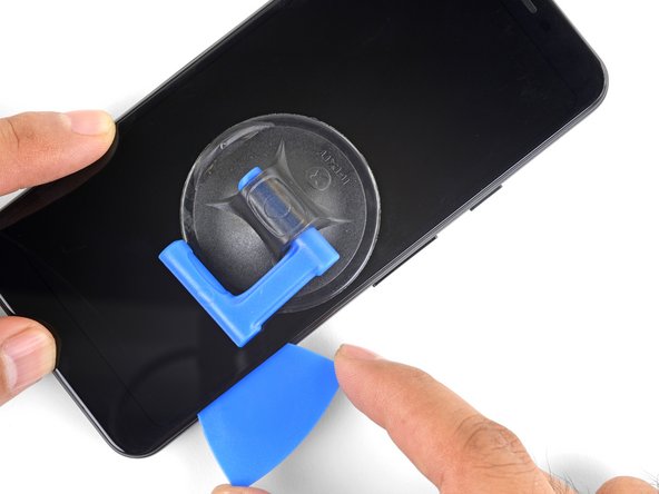
– Get a suction cup and place it near the right edge of your screen.
– Pull on the suction cup with a nice firm grip.
– Now, carefully slide the pick into the gap – don’t go too crazy, just a tiny bit, about 1 mm.
– If you need help, you can always schedule a repair
Step 4

If you feel the pick hitting a ridge, take a break! You might be touching the OLED panel. Just angle the pick a bit and try again. No worries, we’ve all been there.
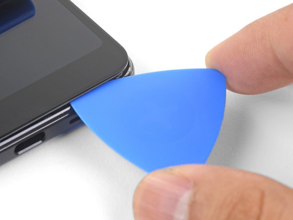
Let’s get started with this step. To avoid damaging the OLED panel, we’ll show you how to carefully insert the pick before slicing either of the phone’s long edges. If you need help, you can always schedule a repair
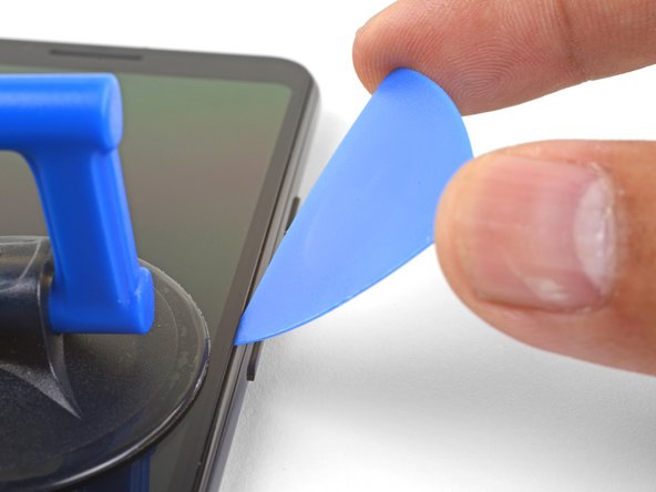
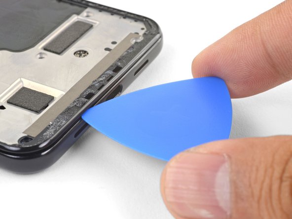
– Slide your pick in the gap, just a millimeter deep, and tilt it up to a sharp angle. You’re doing great!
– Once you’re at that angle, gently nudge the pick into the gap about 1/4″ (6 mm). It should glide right under the OLED panel like a champ!
Step 5


Keep that pick to a cool 1/4″ (6 mm) or less, or you might just give the screen’s flex cable a little too much love and end up with a surprise!
Step 6

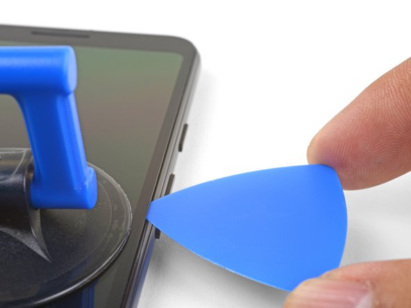
Carefully slice around the bottom edge of your phone, but don’t insert the pick more than 1/4″ (6 mm) – we don’t want any accidents!
Having trouble slicing through a corner? Try applying a heated iOpener to the corner for about a minute, then give it another shot. If you need help, you can always schedule a repair
– Let’s get that pick sliding around the bottom right corner to cut through the adhesive. You got this!
– Keep slicing along the bottom edge of the phone and around the left corner. You’re doing awesome!
Tools Used
Step 7


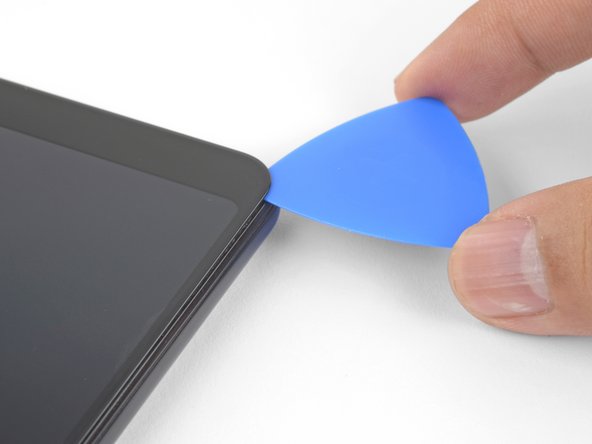
– Gently slice along the left edge of the phone, making sure to angle your pick just right beneath the OLED panel. Aim to insert it no more than 1/4″ (6 mm) for a smooth experience!
– For the best angle under the OLED panel, carefully insert the tip of the pick up to 1 mm in, tilt it upwards, and then gradually push it in 1/4″. You’ve got this!
Step 8


– Gently glide your pick along the top edge, making sure to keep it no deeper than 5/16″ (8 mm) in. You’ve got this!
Step 9


Be careful not to remove the screen just yet – it’s still connected to the phone by a flex cable located near the left edge. If you need help, you can always schedule a repair
– Now that you’ve managed to slice through the edges, gently fold open the right edge of the screen like it’s a fancy book waiting to be read.
– Grab an opening pick and effortlessly glide it along to sever any leftover sticky stuff still holding the screen on.
Step 10


– Now that you’ve cut all the adhesives, it’s time to flip the screen glass over and place it on top of the phone, making sure the screen flex cable is loosely arched. If you need help, you can always schedule a repair
Step 11

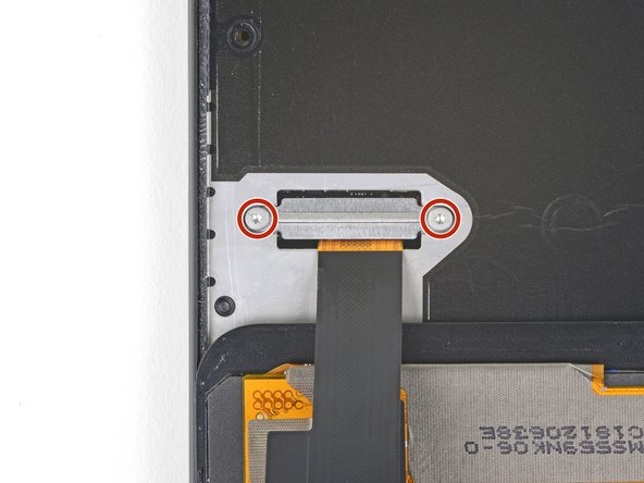

– Gently peel away the black tape that’s keeping the screen connector bracket cozy.
– Unscrew those two T3 screws, each 4.4 mm long, that are holding the screen connector bracket in place.
– Take off the screen connector bracket with care.
– If the tape is still in good shape, feel free to reuse it when putting everything back together. If not, a bit of electrical tape will do the trick!
Step 12


When you’re disconnecting those connectors, keep an eye on those little surface-mounted components around the socket – don’t accidentally nudge them out of place! It’s a delicate operation, but we know you’ve got this. If you need help, you can always schedule a repair.
– Grab your trusty spudger and gently pry up to disconnect that screen flex cable. You’ve got this!
– Now, when it’s time to reconnect, take your connectors and align them carefully. Press down on one side until you hear that satisfying click, then do the same on the other side. Remember, no pressing in the middle! Misalignment can lead to bent pins, and we definitely don’t want any permanent damage. If you need help, you can always schedule a repair.
Tools Used

Step 13


– Let’s kick things off by removing the screen!
– Now, take a moment to compare your shiny new replacement screen with your original one. You might need to move over some extra bits (like the speaker mesh) to the new part, so keep an eye out!
– Ready to put the screen back? Here’s how:
– After you’ve reassembled everything, your screen will go through a calibration dance during the boot-up. Just a friendly reminder: keep your fingers off the screen during this time to avoid any touchy issues later on.
– If you’re using custom-cut adhesives, make sure to follow this guide.
– And if double-sided tape like Tesa tape is your go-to, just stick to this guide as well.
Step 14

– Let’s tackle those fourteen T3 screws that are holding the plastic midframe tight! Here’s what you need to do:
– As you go through this repair, keep a close eye on each screw. Make sure they return to their original homes so they don’t get lost in the shuffle!
– You’ll need twelve shiny 4.3 mm silver T3 screws.
– And don’t forget about the two sleek 4.3 mm black T3 screws!
Step 15


The midframe is still secured by some sneaky plastic clips.
– Gently slide an opening pick into the tiny seam at the bottom of your phone. This little gap is where the plastic midframe meets the back cover, just waiting for your help!
– Now, glide that pick along the seam to pop free the clips that are holding the plastic midframe in place. You’re doing great!
Step 16


– Gently slide the opening pick along the left and right edges of your phone to pop those midframe clips loose.
– Now, lift the bottom edge of the plastic midframe, but hold your horses! Don’t remove it just yet. It’s still connected to the phone by a delicate proximity sensor cable at the top edge.
– When it’s time to put the plastic midframe back, align it with the back cover. Then, give the perimeter a gentle squeeze with your fingers to snap those clips back in place.
Step 17


It’s possible that your proximity sensor connector came loose when you removed the midframe. Don’t worry, it’s an easy fix. If you need help, you can always schedule a repair
– Use the pointy end of a spudger to gently lift and disconnect the proximity sensor connector from the motherboard. It’s like giving the little guy a high five!
– Next, remove the plastic midframe. It’s just like taking off a cozy sweater.
Tools Used
Step 18


Another option is to detach the proximity sensor from the midframe and reconnect it to the motherboard first – a simple step to get you closer to a fully functional device. If you need help, you can always schedule a repair
– Let’s get that proximity sensor back in action during re-assembly! Start by aligning the top edge of the plastic midframe with your phone.
– Now, grab your trusty spudger and gently help the proximity sensor connector make its way onto the motherboard socket. Patience and a little finesse go a long way here!
– Once you’ve got the connector in the right place, feel free to use your finger to give it a gentle nudge to lock it in securely.
– Next up, it’s time to coax the proximity sensor out of its snug little home in the midframe. It’s just a tad sticky, so be careful as you pry it out with the spudger.
– Once liberated, attach the sensor connector back onto its designated motherboard socket.
– Now, thread that sensor cable through the midframe and place the sensor back into its cozy recess. A gentle press with your finger will help it stick back in place like it never left!
Tools Used
Step 19


– Let’s give that battery connector a little nudge! Carefully use the tip of your spudger to gently pry it up and disconnect it from its motherboard socket.
– Now, just bend the battery flex cable a bit so it doesn’t accidentally make contact with the socket. It’s like giving it a little break!
Tools Used
Step 20

– Unscrew those two 3.3 mm T3 screws holding the USB-C port in place and let’s get this party started!
Step 21


– Time to get started. Use your trusty spudger to carefully pry up and disconnect the USB-C port connector from the daughterboard – it’s like freeing a tiny captive.
– Now, let’s remove the USB-C port module. If you need help, you can always schedule a repair
Tools Used
Step 22


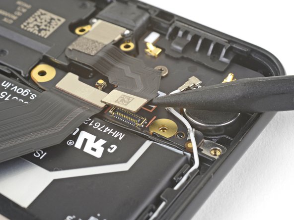
– Time to get connected – or rather, disconnected. Use the point of a spudger to carefully pry up and release the interconnect cable from its daughterboard socket. If you need help, you can always schedule a repair
Tools Used
Step 23
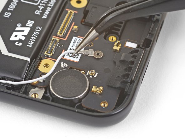

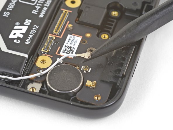
– Alrighty, let’s unhook this little fella! Use your spudger to gently lift and disconnect the white antenna cable from its home on that daughterboard socket. Now, here’s the next step: give those retaining clips a little thrill-ride by carefully de-routing the antenna cable through ’em. Whoo-hoo! If you need help, you can always schedule a repair to get those cables looking like they’re having the time of their lives!
Tools Used
Step 24


– Let’s get started by removing the single 2.7 mm long T3 screw that’s holding the daughterboard in place – it’s time to set it free from the frame.
– Now that the screw is out, you can carefully remove the daughterboard. If you need help, you can always schedule a repair
