How to Replace Google Pixel 3 XL Charging Assembly Guide
Duration: 45 minutes
Steps: 49 Steps
Heads up! This guide was put together by the iFixit crew but isn’t officially backed by Google. Curious? Learn more about our guides here.
Quick safety tip: Discharge the battery below 25% before taking apart your phone. Safety first!
PSA:
Reminder:
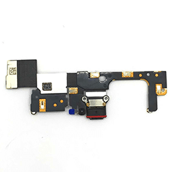
This repair guide was put together by the crew at Salvation Repair, but it hasn’t been officially approved by Google. Want to learn more about how we do things? Check out our other repair guides here. In this guide, we’ll walk you through how to replace the charging assembly on your Google Pixel 3 XL. This includes swapping out the USB-C port and the SIM card reader. Before you dive in, make sure your battery is under 25% to avoid any surprises with a damaged battery. And if your battery is swollen, be extra careful. Pro tip: You don’t have to remove the rear camera from the motherboard, so you can skip that. Oh, and just so you know, the motherboard and loudspeaker can be removed in either order. We do the motherboard first in this guide, but don’t worry—it doesn’t change the repair steps. If you get stuck or need a hand, you can always schedule a repair.
Step 1


– Time to get started. Insert a SIM eject tool, or a trusty paper clip, into the small hole at the bottom of your phone – it’s time to set that SIM tray free.
– Give it a firm press to eject the tray. If you need help, you can always schedule a repair
Step 2

– Pop out the SIM tray from your phone. It’s a quick move that will get you one step closer to a smooth repair.
Step 3


You can use a hair dryer, heat gun, or hot plate to help with the repair, but remember to keep it cool! Overheating your phone can lead to some serious heat damage to the display and internal battery. So, let’s keep things chill while we work on it!
– Warm up your iOpener and gently place it on the right edge of the back cover for about a minute.
– While you let the heat do its thing, take a quick look at the following areas on the back cover:
– Sticky situation—there’s a good amount of adhesive near the bottom of the phone, so keep that in mind.
– Fingerprint sensor cable—be extra careful around this spot to avoid cutting through the cable as you pry.
Tools Used

Step 4


– Get a grip on that back cover by applying a suction cup to the heated edge – the closer to the edge, the better.
– Give the suction cup a firm, steady pull to create some space between the cover and the phone. You got this!
– Next, carefully insert the point of an opening pick into the gap you just created.
– If your phone is a bit older, this might take some extra elbow grease. Don’t worry, just apply some heat to the edge and try again. And if you’re still having trouble, don’t sweat it – you can always schedule a repair with the pros at Salvation Repair.
Step 5


– Gently glide the opening pick along the right edge to cut through that sticky adhesive like a pro.
– Remember, that adhesive can get a bit grumpy and toughen up when it cools down. If it does, just warm it up again to make slicing a breeze.
– Once you’ve made that cut, pop an opening pick into the seam to keep the adhesive from sealing back up on you.
Step 6

– Let’s get this repair started! Apply some heat to the bottom of the back cover using a heated iOpener for about a minute. If you need help, you can always schedule a repair
Tools Used
Step 7


Take your time as you carefully slice around the corner to avoid any cracking of the panel. If things get tough while slicing, don’t hesitate to apply some more heat.
– Grab an opening pick and gently glide it around the bottom right corner, then keep it rolling along the bottom edge of your phone.
– Once you’ve made some progress, pop a pick in the edge to keep that sticky adhesive from sealing back up!
Step 8


– Keep that heat coming and slice away at the rest of the phone’s edges!
– Take it easy as you glide along the left edge. If your pick feels like it’s caught up near the top, you might have bumped into the fingerprint sensor. Just pull back a bit and give it another go.
– Make sure to slice through those thicker adhesive spots near the bottom and right edge of the phone.
Step 9

– Alright, let’s get this party started! Gently pry up the right edge of the back cover. You got this!
– Now, take that trusty opening pick and slice through any remaining adhesive along the edges. Just like butter! You’re doing great! If you need help, you can always schedule a repair.
Step 10


Keep a little wiggle room on that fingerprint sensor cable, and make sure it doesn’t get squished. Your device will thank you later!
– Let’s get started by swinging the right edge of the back cover upwards and resting the flipped panel along the left side of the phone – easy does it!
– Now’s a great time to power on your phone and test all functions before sealing it up. Just remember to power it back down completely before you continue working.
– When you’re reassembling, be sure to follow our guide to install custom-cut adhesives for your back cover – it’s a breeze!
– If you replaced the fingerprint sensor, you’ll need to use a software tool to get your phone to recognize the new sensor. If you need help, you can always schedule a repair with Salvation Repair.
Step 11

– Grab your trusty tweezers and gently lift the yellow tape covering the fingerprint sensor connector. You’ve got this!
Tools Used

Step 12


When working with the flex cable, be extra careful not to touch the metal contacts with your tweezers—those little guys can cause a short if you’re not paying attention. Take it slow, and if you need a hand, you can always schedule a repair.
– Time to get started! Use the point of a spudger to carefully pry up the black lock bar on the fingerprint sensor’s ZIF socket – it’s like opening a little door.
– Now, gently grasp the cable’s tab with your fingers or tweezers and carefully pull the flex cable out of the socket. If you need help, you can always schedule a repair

Step 13

– Pop off that back cover like a champ!
– Check out this guide to make sure you stick on the new back cover adhesive just right.
Step 14

– Time to unscrew! First, take out those four T3 screws holding the metal cover bracket in place:
– As you tackle this repair, keep an eye on each screw and remember where it belongs – it’s like a little puzzle!
– Three screws measuring 4 mm in length
– One screw measuring 3 mm in length


Step 16


– Time to get started – use the point of a spudger to carefully pry up and disconnect the battery connector from its socket. Take your time and be gentle.
– Now, bend the battery cable so the connector won’t accidentally touch the socket. If you need help, you can always schedule a repair
Tools Used
Step 17

– Let’s get those screws out! You’ll have to unscrew the five T3 screws to remove the motherboard shield.
– You’ve got this! Now take out those three 4 mm long screws.
– Keep up the great work! Now remove those two 3 mm long screws.

Step 19

– Time to loosen things up! Unscrew the three 3 mm long T3 screws holding the front camera bracket in place. Get those screws out, and you’re one step closer!
Step 20

– Time to say goodbye to the front camera bracket! Carefully remove it and give yourself a pat on the back for taking this step. You’ve got this!
Step 21


Take extra care not to bump those tiny surface-mounted components around the sockets. They’re like little friends that don’t want to be disturbed!
– Time to get those cameras disconnected. Use the point of a spudger to carefully pry them up from their motherboard sockets. If you’re not feeling confident, don’t worry – you can always schedule a repair and let the pros handle it.
Tools Used
Step 22


The cameras are held in place with a little bit of adhesive, so be gentle when handling them. If you need help, you can always schedule a repair
– Gently use the flat end of a spudger to lift and loosen the camera modules from their slots. No need to rush, just take it slow and steady!
Tools Used
Step 23

– Time to say goodbye to those front-facing cameras! Gently remove them and let the magic happen.
Step 24

Alright, let’s give that motherboard a little more breathing room! Removing this screw will give you a bit more space to work with.
– Unscrew the 4 mm long T3 screw that’s holding down the top-right corner of the loudspeaker. You’ve got this!
Step 25

– Let’s get started by removing the two 3 mm long T3 screws that hold the button array connector bracket in place.
Step 26

– Take off the bracket holding the button array connector. It’s like unwrapping a gift, but the gift is your device getting a little more free!
Step 27


– Grab your trusty spudger and gently use the point to lift and disconnect the earpiece connector from its socket on the motherboard.
– Carefully peel back the connector pad around the earpiece socket to keep everything in tip-top shape.
Tools Used

Step 29

– Let’s get started by using the point of a spudger to carefully pry up and disconnect the following connectors:
– Charging coil connector
– Left squeeze sensor connector
– Display connector
– Right squeeze sensor connector
– Loudspeaker connector
– USB-C port connector. If you need help, you can always schedule a repair
Tools Used
Step 30

– Unscrew those two 3 mm T3 screws holding the motherboard in place and let the magic begin!
Step 31


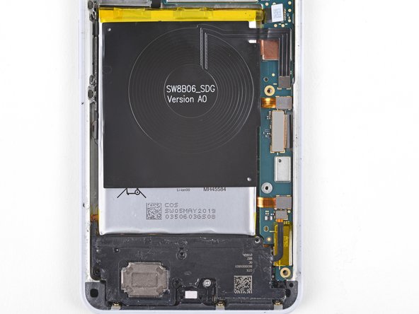
Hey there, tech-savvy friend! If your earpiece speaker decides to take a little break and pops open (like the third photo in this step), don’t panic! Just gently nudge it back into place. Make sure it’s snug and you’re good to go. If you need help, you can always schedule a repair
– Slide the point of a spudger under the motherboard, right by the rear-facing camera module.
– Gently pry it up to free the motherboard from its snug spot.
– The motherboard needs to sneak past the earpiece speaker cable. Just a heads up, if you press too hard on the earpiece cable, the speaker might pop open. To avoid that little mishap, use your finger to hold down the earpiece module while you carefully wiggle the motherboard out.
– If the motherboard seems to be playing hard to get, double-check to ensure all the connectors are unplugged.
Tools Used
Step 32


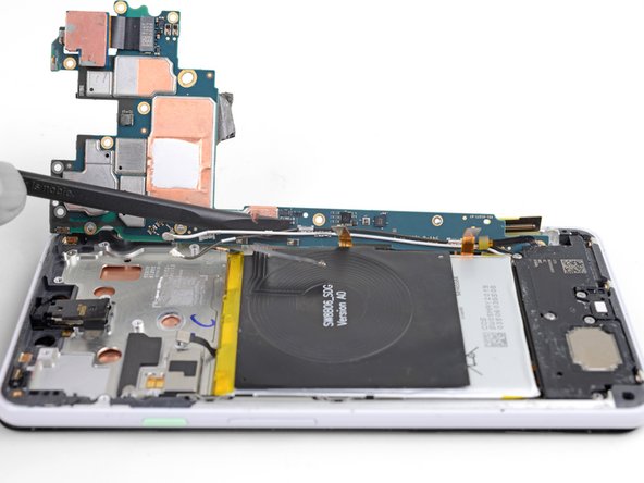
Hey, hold up! We don’t want to go pulling the motherboard out just yet. It’s still hanging out with the phone. Let’s take things slow and steady. If you need a helping hand, you can always schedule a repair.
– As you dive into this step, remember to give those antenna cables a little wiggle room while they’re hanging out at the bottom leg of the motherboard.
– Gently lift the top half of the motherboard just enough to free it from its cozy spot.
– Now, give the left edge of the board a twist to gracefully slide it out of the phone, and let it chill on the right edge for a moment.
Step 33


Be gentle when handling the cables, as they can be delicate. To remove them, carefully pry the clips close to the base – it may take a little patience, but you’ve got this! If you need help, you can always schedule a repair
– Grab your spudger and gently use the flat side to lift and loosen the black and white antenna cables from their clips on the motherboard. No need to rush—just a light touch will do!
Tools Used

Step 35
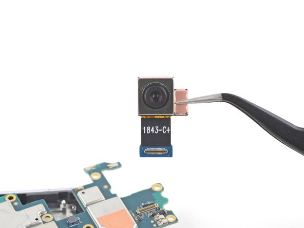

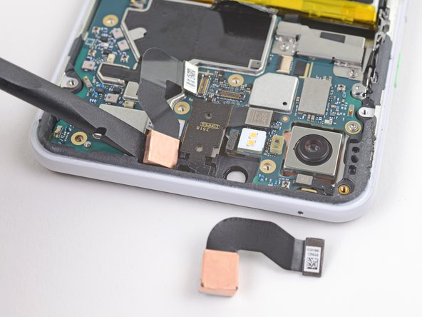
When swapping in a shiny new motherboard, here’s how to smoothly relocate that rear-facing camera:
– First things first! Take a good look at your shiny new replacement part and compare it with the original. If you spot any leftover bits that need to be moved over or if the new part is sticking more than your last vacation souvenir, go ahead and peel off those adhesive backings before diving into installation.
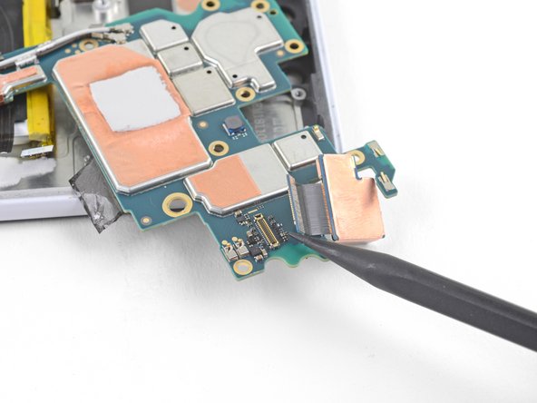
– Now, grab your trusty spudger and carefully use its pointy end to gently pry up and disconnect the rear-facing camera from its cozy socket on the motherboard. We want to be careful here, no need for surprises!
– Once that’s done, it’s time to liberate the rear-facing camera and give it a new home on your replacement motherboard. You’ve got this!
Tools Used
Step 36

If you’ve already taken out the motherboard, then that top right loudspeaker screw is already off the list!
– Let’s get started by unscrewing the four T3 screws that are holding the loudspeaker in place:
– Three screws that are 4 mm long
– One screw that measures 3.9 mm long
Step 37


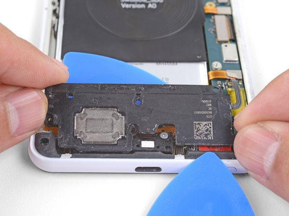
– Let’s get started by slipping the point of an opening pick under the bottom right corner of the loudspeaker – easy does it!
– Now, gently slide the pick in to loosen the right side of the loudspeaker. If you need help, you can always schedule a repair
Step 38


– Time to get this repair started – carefully insert the point of an opening pick under the top edge of the loudspeaker, just below the battery. Take your time and be gentle.
– Now, slide the opening pick in to slice through the adhesive gasket under the loudspeaker. Remember, if you need help, you can always schedule a repair
Step 39
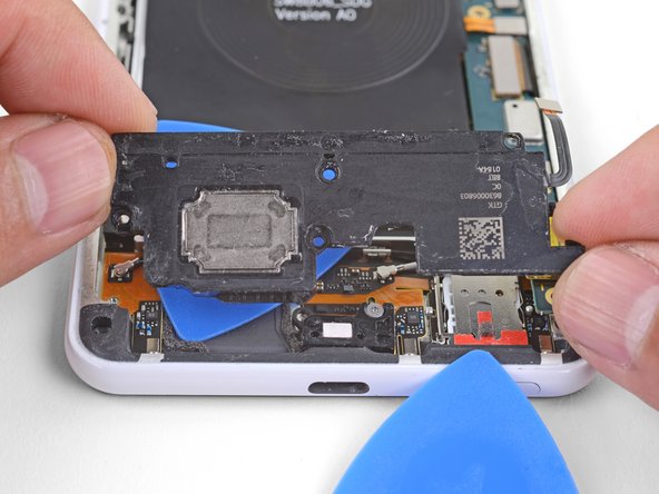
– Gently lift the loudspeaker out and give it a little wiggle to break free from any sticky spots.
– Say goodbye to the loudspeaker as you remove it from its cozy home.
– Before you pop that loudspeaker back in, consider cleaning up any leftover adhesive from the frame and adding some fresh adhesive for a snug fit.


Step 41

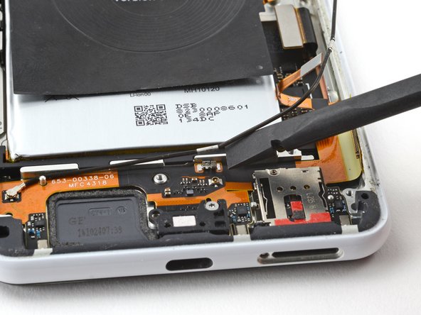
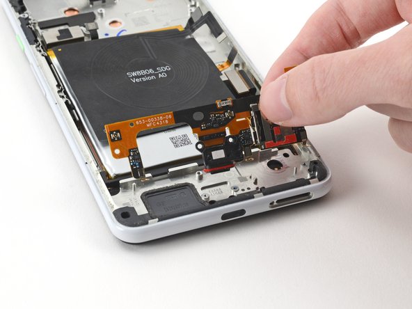
– Let’s get started by removing the white coaxial cable from your phone. This is a simple step to begin the repair process. If you need help, you can always schedule a repair

Step 43
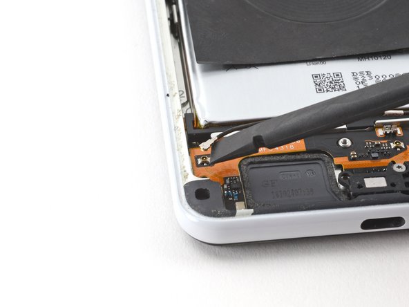

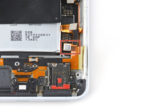
– Now it’s time to carefully disconnect the black coaxial cable connector from the charging assembly. Use the flat end of a spudger to gently pry it up and set it free. If you need help, you can always schedule a repair
Tools Used
Step 44

– Alright, let’s unplug that black coaxial cable from your phone. Easy peasy, right?
Step 45

– Grab your trusty T3 Torx screwdriver and let’s tackle those three 2.4 mm screws that are holding the charging assembly to the frame. You’ve got this!
Tools Used

Step 46

– Let’s get started by using a T3 Torx screwdriver to carefully remove the 3.9 mm screw that’s holding the USB-C port bracket in place. If you need help, you can always schedule a repair
Tools Used
Step 47
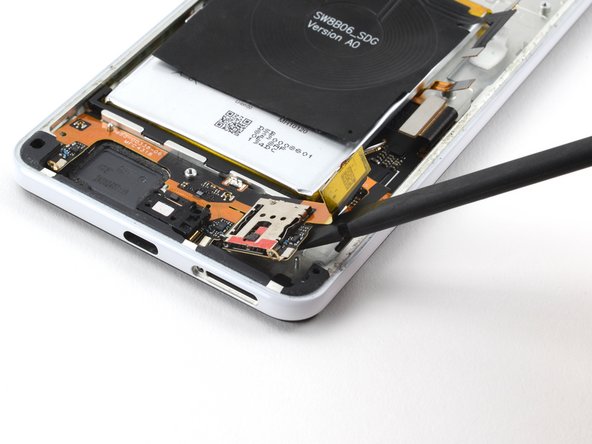

First things first, if you haven’t already popped out the SIM card tray, do that now! You won’t be able to get to the charging assembly until that tray is out of the way.
Now, keep an eye out – the right side of the charging assembly is snugly held in place by a little peg right next to the SIM card reader. Make sure to give it some attention!
– Let’s get that charging assembly out! Use the flat end of your trusty spudger to gently pry it loose from the frame. No need to force it, just slide it under the right side and let it pop free. If you need a little extra help, you can always schedule a repair
Tools Used


Step 49

The USB-C port is held snugly to the frame by a cheerful red gasket. You might have to wiggle the charging assembly a bit to free it from the frame, but don’t worry, you’ve got this!
– Gently detach the charging assembly from the frame—like a hug that’s lasted a little too long!
– As you put things back together, be sure the right squeeze sensor cable is cozy and resting above the USB-C port cable. They like to be neighbors!
– Remember, the right squeeze sensor cable hangs out next to the bottom right corner of the battery, just chilling there.