Samsung Galaxy On5 Motherboard Replacement Guide: DIY Step-by-Step
Duration: 45 minutes
Steps: 16 Steps
Hey there, tech wiz! This guide is here to help you swap out a motherboard in your Samsung Galaxy On5 like a pro. Before diving in, make sure your issue is truly a motherboard problem. Maybe it’s just a wonky screen or a loose wire. If you’re certain it’s the motherboard, this guide will walk you through the process, step by step. Need a helping hand? You can always schedule a repair.
Step 1

– Alright, let’s get this show on the road! Find that little notch on the side of your device. That’s your key to opening up the back casing.
Step 2


– Grab a plastic prying tool or just use your fingernail to snap the back cover off your phone.


Step 4

Hey there, champ! We don’t want to be a buzzkill, but using a metal pry tool on your device can cause some serious damage. It’s best to stay away from those metal dudes. Just a friendly reminder, if you need help, you can always schedule a repair with us. We’re happy to help!
– First things first, let’s give your phone a little breather by popping out the SIM card and microSD card. They deserve a little time off too!
– Grab a trusty plastic pry tool and gently slide out both cards. You’ve got this!
Step 5


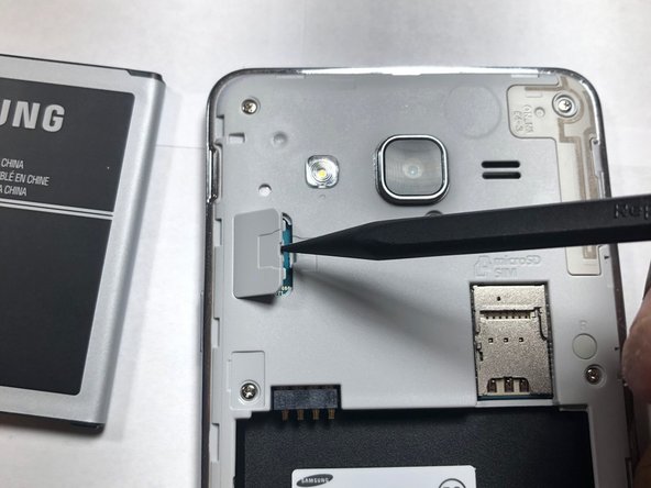
This part might be a bit tricky to open. No worries! Just take your time and be gentle. You don’t want to push too hard – that could make the ribbon unhappy. If you need help, you can always schedule a repair.
– Grab your trusty plastic Spudger tool and gently pry open the cover of the LCD ribbon cable. You’ve got this!
Tools Used

Step 6
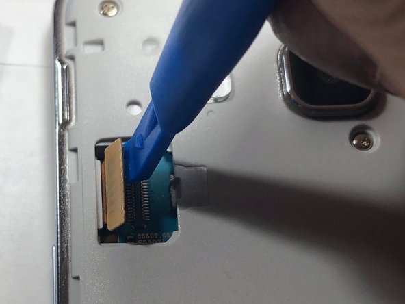

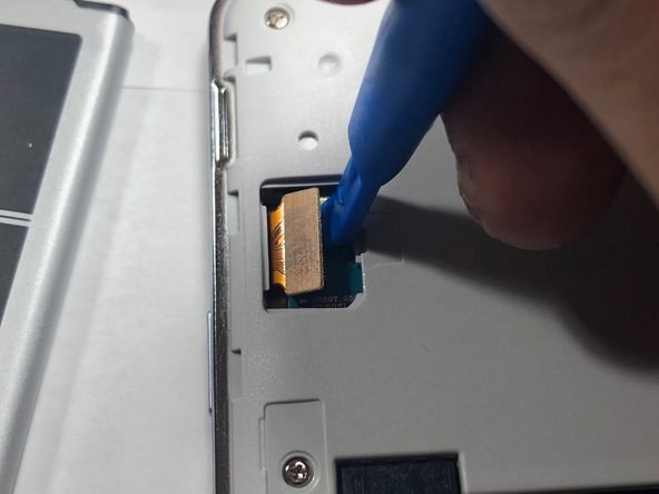
Be careful not to use a metal pry tool, as it can cause damage to the logic board and ribbon cable. If you’re not sure, don’t worry – you can always schedule a repair and let the pros handle it.
The LCD ribbon cable is like a messenger between the logic board and the LCD screen, sending important signals to get your display up and running. If you need help with this step or any other part of the repair, you can always schedule a repair
– Alright, time to give that LCD ribbon cable a little wiggle room! Grab your trusty plastic pry tool (we’re talking gentle here, folks) and carefully pop that cable off the logic board. You got this!
Step 7


All 9 screws are identical in size, so you don’t have to worry about mixing them up!
– Grab your trusty Phillips #00 screwdriver and give those 9 screws the boot! Once they’re out, stash them somewhere safe – you don’t want to lose those little guys. If you need help, you can always schedule a repair
Step 8


This step might take a little while because of the glue that’s keeping the LCD and back assembly snug together. Just take your time and gently work your way around the screen’s edge to loosen that adhesive.
If you’ve got a heat gun handy, feel free to use it to warm up the glue. A little heat goes a long way in making it easier to separate the LCD from the back assembly.
– Now, let’s carefully separate the LCD from the back assembly. Grab that handy iFixit plastic pick and gently pry it apart. Take your time, and if you’re feeling unsure, you can always schedule a repair.
Step 9
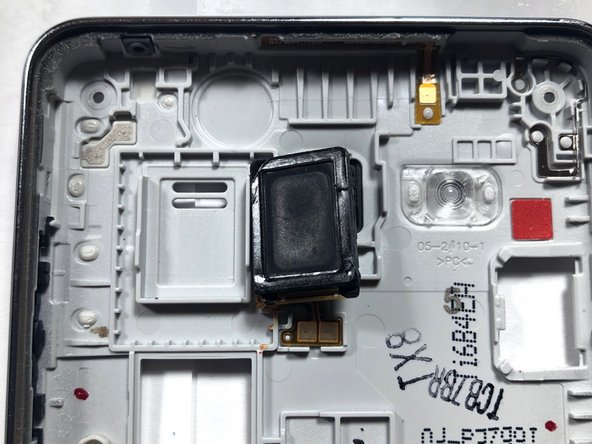

– After you’ve successfully separated the LCD from the back assembly, take a moment to locate the speaker nestled in the back assembly.
– Once you’ve found it, grab your trusty plastic pry tool and gently pop the speaker out of its cozy home. Then, slide in the new speaker like a pro!
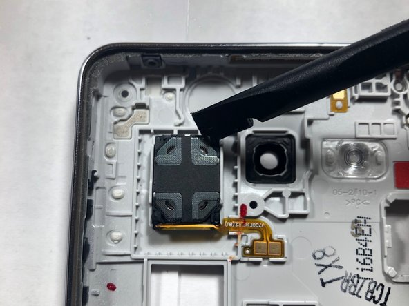
Step 10

When working with sensitive electronics, it’s best to use a plastic pry tool instead of metal tools to avoid any damage. If you need help, you can always schedule a repair
– Time to give that front-facing camera a little lift! Use a plastic pry tool to gently nudge it out of its cozy little home. You’ve got this!
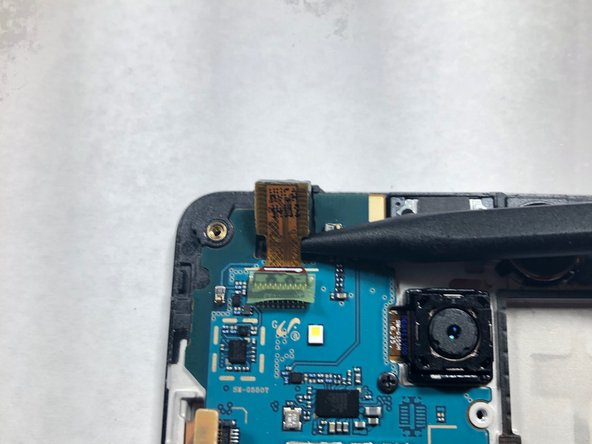
Step 11

– Now that the camera is out of the housing, it’s time to give it a little break from the logic board. Gently disconnect the camera to free it from the board.
Step 12

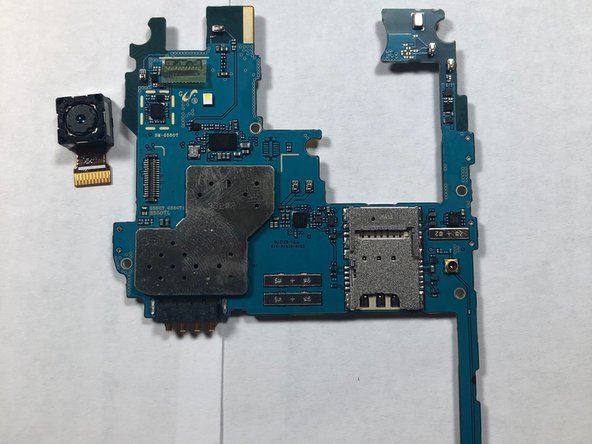
– You’ve successfully removed the front-facing camera – nice work! You’re one step closer to getting your device back in action. If you need help, you can always schedule a repair
Step 13

When reaching for that metal tool, just take a moment to consider where you’re putting that bit. Trust us, the motherboard doesn’t bounce back from damage like other things do!
– Grab your trusty Phillips #00 screwdriver and give that rear-facing camera screw a little twist to the left. It’ll come right off!
Tools Used

Step 14
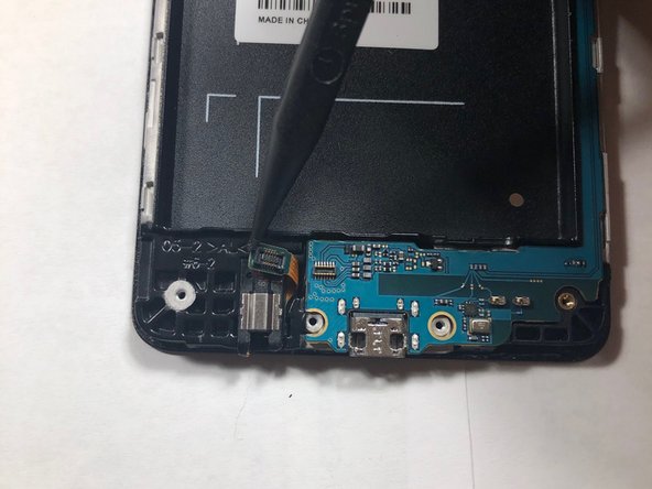

– Grab your trusty plastic pry tool and gently disconnect that headphone ribbon from the motherboard. You’ve got this!
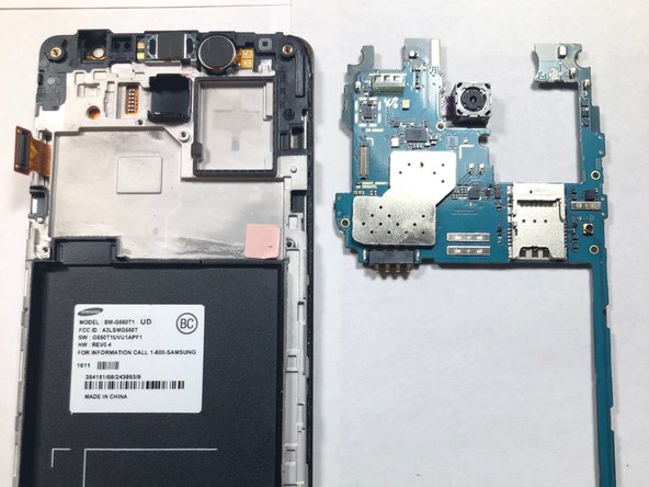
– Now, it’s time to lift the motherboard out of the LCD housing. Just carefully raise it from the ends of the logic board, and you’ll be on your way!
Step 15

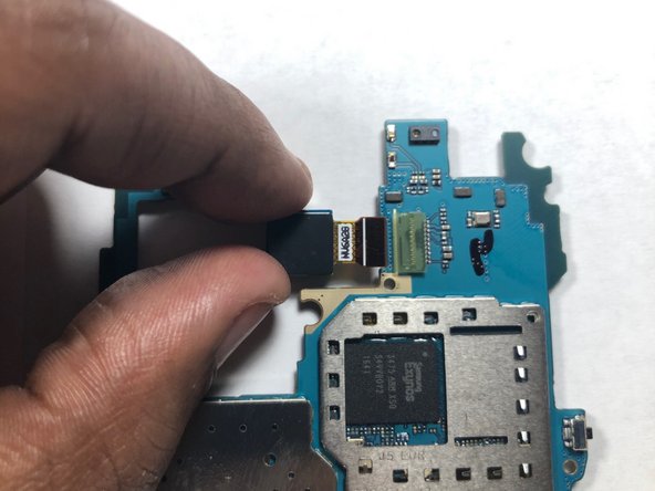
– Time to get hands-on – flip that logic board so the camera lens is facing downwards.
– Gently use your finger to release the camera from its connection on the logic board. If you need help, you can always schedule a repair
Step 16

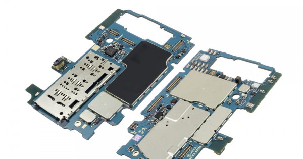
– Now that you’ve removed the cameras from the logic board, it’s time to swap it out with a new one. If you need help, you can always schedule a repair