Samsung Galaxy On5 Camera Replacement Guide
Duration: 45 minutes
Steps: 15 Steps
Ready to give your Samsung Galaxy On5 a little makeover? This nifty guide is here to help you swap out both the front and rear cameras with ease. Let’s get those lenses sparkling again! And remember, if you need help, you can always schedule a repair.
Step 1

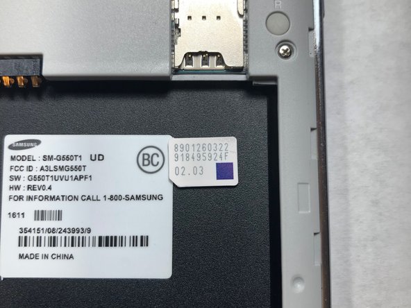
– Find the side notch – it’s the key to unlocking the back casing.
Step 2


– Grab a plastic prying tool or your trusty fingernail and gently nudge the back cover of your phone off. You’re doing great!
Step 3


Hey, let’s be careful around that battery! Lithium-ion batteries can get a little *too* excited if they meet air, so let’s keep them covered up. If you need help, you can always schedule a repair.
Step 4

Be careful not to use a metal pry tool, as it can cause damage to the cards and/or card holder. If you’re not sure about this step, don’t worry – you can always schedule a repair and let the pros handle it.
– First things first, let’s make sure those precious SIM and microSD cards are safe and sound. Grab your handy-dandy plastic pry tool and gently slide those babies out. You got this!
Step 5


Be gentle when opening this part, as it can be a bit tricky. Take a deep breath, go slow, and avoid applying too much pressure – you don’t want to accidentally damage that delicate ribbon. If you need help, you can always schedule a repair
– Grab your trusty plastic Spudger tool and gently work your magic to lift the LCD ribbon cable cover. It’s easier than it sounds!
Tools Used

Step 6
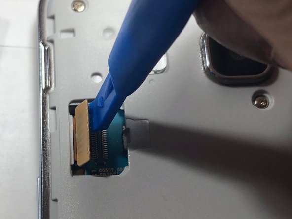

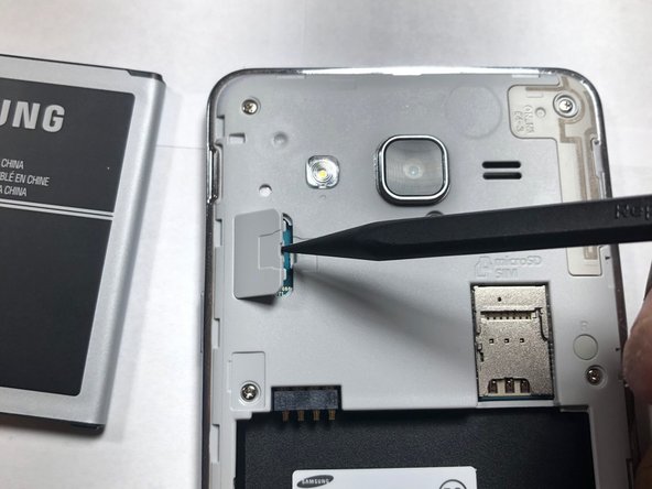
Avoid using a metal pry tool, folks! Those shiny metal gadgets can be a bit too rough and might mess up your logic board and ribbon cable. Keep it gentle and safe!
This nifty little LCD ribbon cable works hard to relay signals from the logic board straight to your screen. It’s a crucial component for keeping your device looking sharp!
– Alrighty then, grab that trusty plastic pry tool of yours and gently wiggle away the LCD ribbon cable from the logic board. This is where being the repair whiz kicks in! If you need help, you can always schedule a repair.
Step 7


No need to worry about remembering different sizes here – all 9 screws are the same!
– Grab your trusty Phillips #00 head and carefully remove all 9 screws. Set them aside in a safe spot where they won’t get lost. If you need help, you can always schedule a repair
Step 8


Hang tight, this might take a little while since the glue is doing its job holding the LCD and back assembly snugly together. Gently work your way around the screen’s edge to start loosening that stubborn glue.
Got a heat gun? Perfect! A little warmth can work wonders on the glue, making it a breeze to separate the LCD from the back assembly.
– Time to get this repair started. Use an iFixit plastic pick to carefully pry the LCD away from the back assembly. If you need help, you can always schedule a repair
Step 9
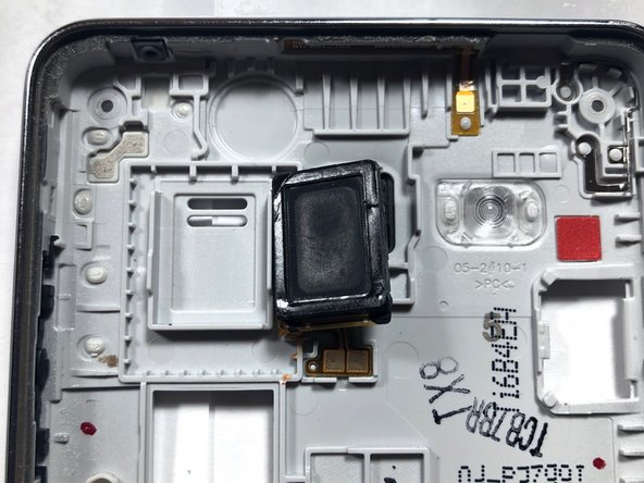

– Alright, buddy, now that the LCD and back assembly are separate, find the back assembly where the speaker is hanging out.
– Grab your trusty plastic pry tool, give that speaker a gentle nudge, and swap it out with a brand new one. You’ve got this!
Step 10

Always opt for a plastic pry tool instead of metal when you’re handling those delicate electronic devices. Your gadgets will thank you for the gentle touch!
– Time to get that front-facing camera out of its housing. Use a plastic pry tool to gently lift it out – easy does it! If you need help, you can always schedule a repair
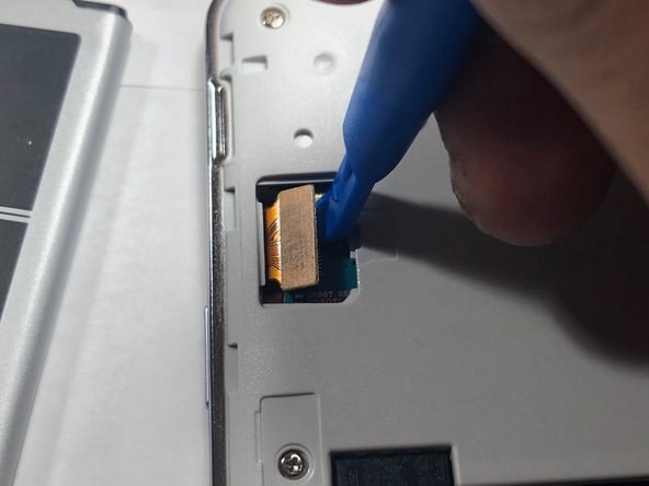
Step 11

– Alrighty, time to get our camera out of its cozy little home! Once you’ve done that, don’t forget to give it a little break from its trusty logic board buddy. If you need help, you can always schedule a repair!
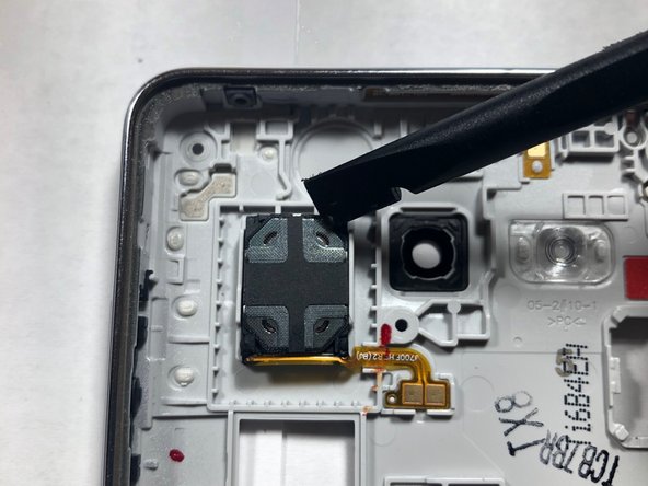
Step 12

– High five! You just popped out that front-facing camera like a champ. Ready to move on to the next step?
Step 13

Hey there, remember those metal tools we talked about? Be super careful about where you put them! A slip of the hand can really put a damper on things. If you need a bit of help, you can always schedule a repair.
– Alright, time to get that camera lens out! Grab your trusty Phillips #00 screwdriver and give that screw securing the rear-facing camera a little twist to loosen it up.
Tools Used

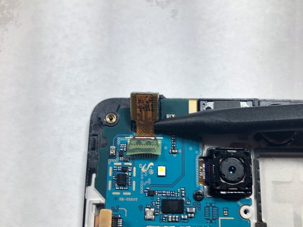
Step 14
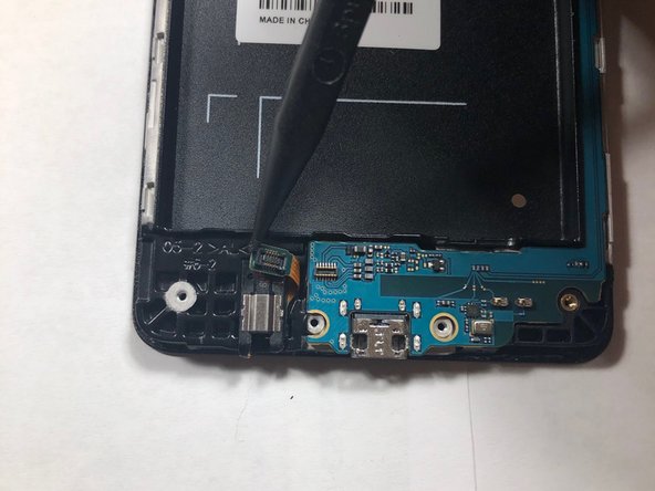

– Let’s get that headphone ribbon disconnected! Use a plastic pry tool to gently separate it from the motherboard.
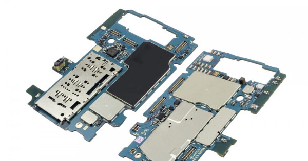
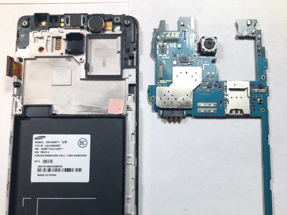
– Time to free the motherboard! Lift it up from the ends and give it a little wiggle to remove it from the LCD housing.
Step 15
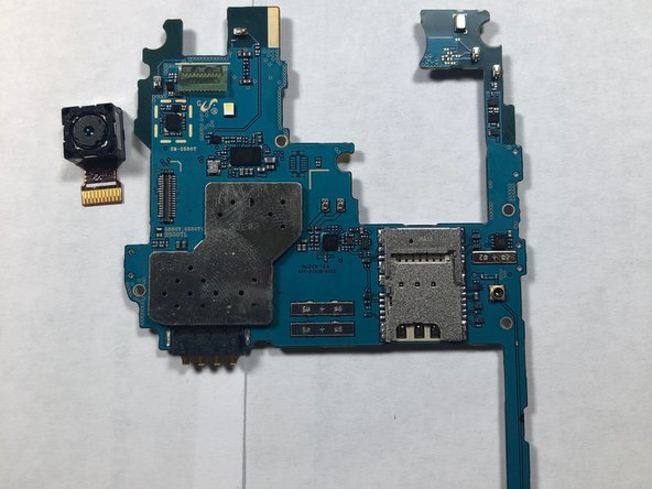

– Flip the logic board over so the camera lens is facing down, like it’s shy and wants to hide.
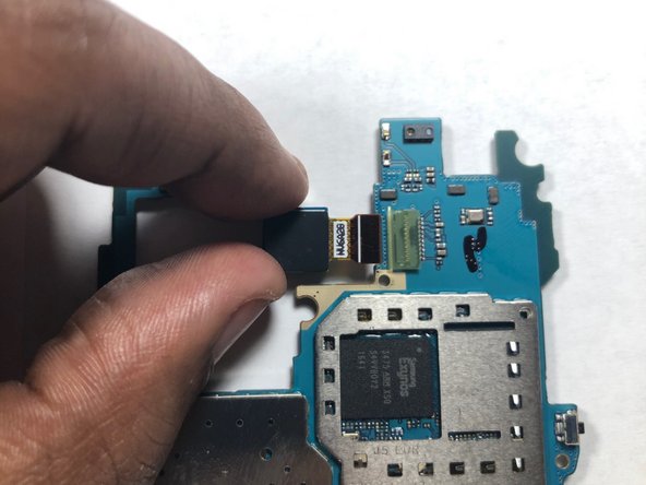
– Give the camera a gentle nudge with your finger to disconnect it from the logic board. It’s like giving it a little high five to say goodbye.