Samsung Galaxy Note20 Motherboard Replacement Guide
Duration: 45 minutes
Steps: 33 Steps
Hey there! Just a friendly reminder to keep things safe: make sure your battery is below 25% before you dive into disassembling your phone. It’s a smart move!
Alright, let’s get this motherboard swap party started! First things first, let’s make sure we’re all safe by chilling out the battery to below 25%. This keeps things cool and calm in case anything goes awry during the swap. You know, just a little safety precaution. If your battery’s feeling a little puffy, be extra careful, okay? Need a hand? No sweat, you can always schedule a repair.
Step 1


No worries if you accidentally poked the SIM eject tool into the microphone hole! Chances are, your microphone is just fine.
– Let’s pop out that SIM card! Grab a SIM eject tool, a bit, or even a straightened paperclip, and gently insert it into the little hole on the top edge of your phone.
– Now give that tool a gentle push and watch as the SIM card tray slides out.
– Sweet! Just lift out the SIM card tray and you’re good to go! If you need help, you can always schedule a repair
Step 2

Make sure to completely turn off your phone before diving into disassembly—safety first, right?
You can use a hair dryer, heat gun, or hot plate to warm things up a bit, but be cautious not to turn your phone into a sauna. Remember, the screen, internal battery, and plastic rear cover can get a bit cranky with too much heat!
– Let’s get this party started! Heat up an iOpener and give the left side of the rear cover a nice warm hug for about a minute.
Tools Used

Step 3


Hey, careful! Don’t push that opening pick more than 5mm into the phone. You might accidentally poke a hole in the phone’s insides. If you need help, you can always schedule a repair.
Don’t worry if this part takes a little effort – especially if your phone has been around for a while. If it’s not budging, try applying some extra heat to the edge and giving it another shot. If you need help, you can always schedule a repair
– Get that suction cup ready and stick it right on the heated edge of the rear cover. Closer to the edge, the better!
– Now, pull up on that suction cup with some good ol’ fashioned strength. You’re aiming to create a tiny little gap between the rear cover and the frame.
– Time to slide in an opening pick. You got this!
Step 4


As you carefully work your way around the phone’s edges, remember to keep your pick no deeper than 5 mm. We want to avoid any accidental run-ins with the delicate internal parts—let’s keep everything intact and happy!
– Gently glide that opening pick along the left edge and make your way down to the bottom left corner to slice through the adhesive like a pro.
– Keep that pick snug in the bottom left corner to stop the adhesive from playing tricks and sealing back up.
Step 5


If the rear cover is still stuck to the frame after cutting through all four sides, no worries! Try giving that adhesive another little slice with your opening pick.
You can insert each new opening pick into the gaps created by the opening picks already in each corner. Keep going, you’re doing great!
– Alright, let’s keep this momentum going! Repeat the heat and cut routine on those remaining three sides of the rear cover. It’s like a dance, trust me.
– As you move along, pop a handy opening pick into each corner to keep that adhesive from getting too cozy. We want those parts to stay separated!


Step 7

If these screws are still in their cozy home, they might be a bit tricky to coax out since they’ve got some threadlocker making themselves comfy in there.
As you go through this repair adventure, keep an eye on each screw and make sure it returns to its original spot when you’re done!
– Alright, time to get those screws out! Grab your trusty Phillips screwdriver and give those six 4.0 mm screws holding the motherboard shield in place a little twist. They’ll be coming out in no time!
Step 8


Hey there, remember to be gentle with the motherboard shield. Those edges are kinda sharp, so don’t go poking yourself, okay?
– Time to get up close and personal with your device’s internals. Use a trusty pair of tweezers to carefully lift and flip back the motherboard shield. If you need help, you can always schedule a repair
Tools Used

Step 9


Don’t be a hero! Just gently pry under the edge of the connector to avoid any mishaps. We want to keep things sweet and safe for the socket and its buddies.
– Grab your trusty tweezers and gently hold that motherboard shield out of the way. Now, take the pointed end of your spudger and carefully pry up the battery press connector. Easy peasy!
– When it’s time to re-attach those press connectors, just align one side and give it a gentle press until you hear that satisfying click. Then do the same on the other side. Just a friendly tip: steer clear of pressing down in the middle. If things get misaligned, those pins can bend, and nobody wants that kind of permanent damage!

Step 10


– Now, get your trusty tweezers and gently hold the motherboard shield out of the way. Next, grab your spudger (that handy little tool!) and use the pointy end to carefully pry up the wireless charging coil press connector. You got this!
Step 11


The wireless charging coil’s got itself a little sticky surprise to hold onto your tech! It’s like a fun, bouncy friendship bracelet for your device!
– Get a good grip on the motherboard shield with your fingers – it’s time to get started!
– Carefully peel the wireless charging coil up and away from the device, taking your time to avoid any damage.
– Now, remove the wireless charging coil completely. If you need help, you can always schedule a repair
Step 12

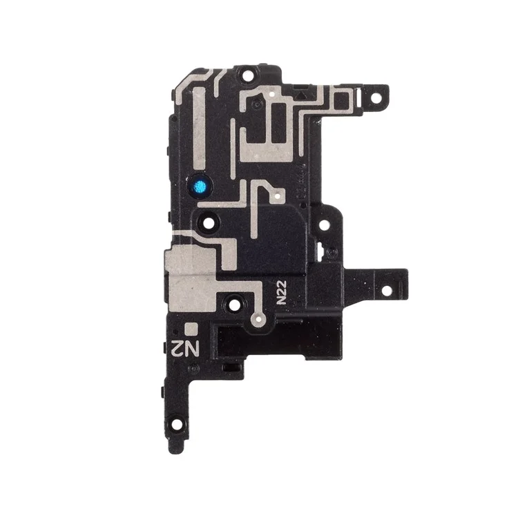
– Grab your trusty Phillips screwdriver and unleash its power by unscrewing the five 4.0 mm screws that are holding the loudspeaker snugly to the frame. You’ve got this!
Step 13


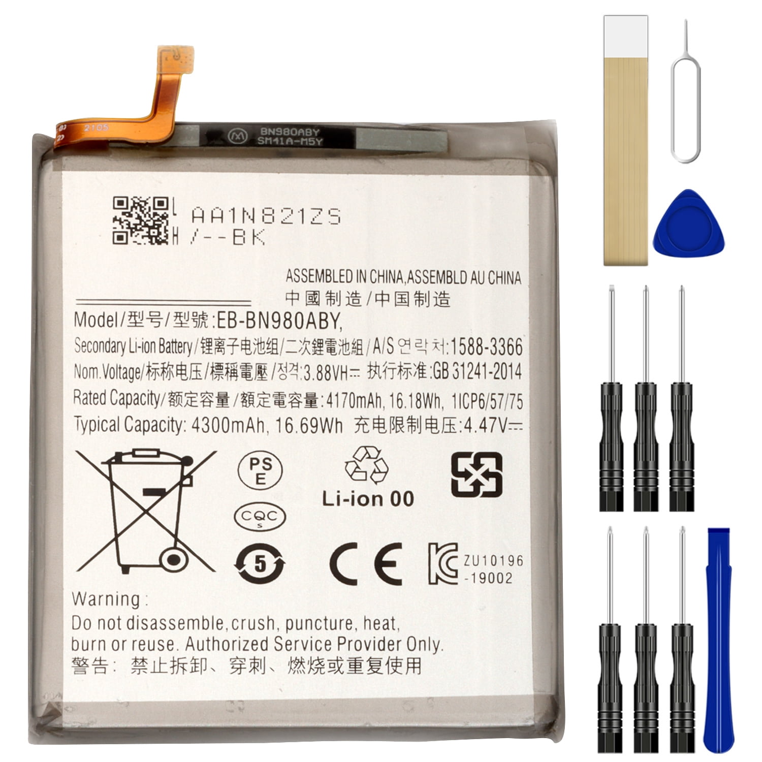
Hey there, be super careful when you’re using those tweezers around the battery. You don’t want to poke or bend it, because a damaged battery could leak some not-so-nice stuff or even get a little too hot. If you’re feeling a little uneasy about it, you can always schedule a repair with our awesome crew.
– Let’s get that loudspeaker out! Gently slip the pointed end of your spudger under the loudspeaker, near the top left screw hole.
– Now, use that spudger to carefully pry the loudspeaker away from the frame. Think of it like giving it a little hug goodbye.
– With a pair of tweezers, carefully lift the loudspeaker right out of there. You got this!
Step 14

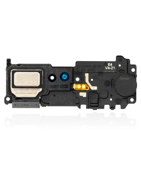
– Alright, time to get those screws out! Using your trusty Phillips screwdriver, give those five 4.0 mm screws holding the earpiece speaker to the frame a good twist and send them packing.
Step 15


The earpiece speaker, that little guy that brings your calls to life, is held onto the frame along the top edge. It’s like a mini party up there!
– Gently slide the flat end of a spudger under the bottom edge of the earpiece speaker. It’s like giving it a little lift!
– Now, carefully pry up the earpiece speaker to detach it from the frame. You’ve got this!
Tools Used


Step 17


Heads up! Since the front-facing camera is just held on by a connector, it might take a little flight when you’re getting things loose. Don’t worry, it’s just a little camera dance party. We’ve got you covered!
– Now it’s time to carefully pry up the front-facing camera press connector – use the pointed end of a spudger to get the job done. If you need help, you can always schedule a repair
Tools Used


Step 19


– Now it’s time to disconnect the secondary interconnect cable from the daughterboard. Use the pointed end of a spudger to gently pry it loose. If you need help, you can always schedule a repair
Tools Used


Step 21


– Grab your spudger and use the pointy end to gently disconnect the display cable from the motherboard. It’s like giving the cable a little high five!
Tools Used
Step 22


– Now it’s time to disconnect the main interconnect cable from the motherboard. Use the pointed end of a spudger to gently pry it loose. If you need help, you can always schedule a repair
Tools Used
Step 23


– Gently use the sharp end of your trusty spudger to unplug that secondary interconnect cable from the motherboard. You’ve got this!
Tools Used
Step 24

– Now it’s time to carefully disconnect the S-Pen press connector from the motherboard – use the pointed end of a spudger to get the job done. If you need help, you can always schedule a repair
Tools Used
Step 25


– Grab your spudger, the pointed end, and gently disconnect that green press connector from the motherboard. It’s like giving the connector a little high five, but don’t get too excited! If you need help, you can always schedule a repair
Tools Used
Step 26


– Now it’s time to get a little tricky – use the pointed end of a spudger to carefully disconnect the touch layer press connector from the motherboard. If you’re not feeling confident, don’t worry, you can always schedule a repair and let the pros handle it.
Tools Used
Step 27

– Grab your trusty Phillips screwdriver and unscrew that 4.0 mm screw holding the motherboard snugly to the frame. You’ve got this!
Step 28


– Let’s get this motherboard out! First, slide that spudger under the bottom left corner of the motherboard. You know the drill, slide it in like you’re opening a treasure chest!
– Now, gently pry upwards to loosen the motherboard from its frame. It’s like giving it a little lift to help it on its way.
– Time to lift that motherboard right out of the phone! It’s like a little dance move, just lift it up with a little care. If you need help, you can always schedule a repair
Tools Used
Step 29

– Flip the motherboard so the rear camera module’s press connectors are facing up – it’s time to get started on this repair
– Now, use the pointed end of a spudger to carefully pry up the upper camera’s press connector from the motherboard. If you need help, you can always schedule a repair
Tools Used
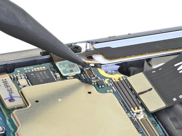
Step 30

– Grab a trusty pair of tweezers and gently lift the upper camera off the motherboard. You’ve got this!
Tools Used
Step 31


– Grab your trusty spudger and gently pry up the lower camera’s connector from the motherboard. It’s like giving it a little nudge to say ‘Hey, it’s time to get disconnected!’
Tools Used
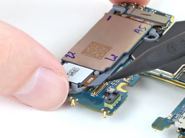
Step 32

– Time to give those lower cameras a little vacation! Gently lift them off the motherboard and set them aside.