Samsung Galaxy Note10+ 5G Rear Camera Replacement Guide
Duration: 45 minutes
Steps: 28 Steps
Alright, gear up for this rad repair sesh! We’re gonna give your Samsung Galaxy Note10+ 5G’s rear camera module a bit of a makeover. It’s a bit of a Behind The Music situation with our buddy, the motherboard. But don’t sweat it! We’ll guide you through every inch of it. Just to let you know, some photos might not align 100% with the steps, but who cares, right? It’s all about the vibe. If you’re struggling, you might want to consider booking a repair with the cool cats at schedule a repair and let ’em handle the magic.
Step 1


– Grab a SIM eject tool, a small screwdriver, or even a straightened paper clip and gently insert it into the tiny hole on the SIM card tray located at the top edge of your phone.
– Give it a good push to pop that tray out!
– Now, carefully pull out the SIM card tray.
Step 2

Make sure your phone is turned off completely before diving into the disassembly fun!
When using heat to loosen things up, be gentle – a hair dryer, heat gun, or hot plate can be super helpful, but don’t overdo it. Your phone’s display and internal battery are sensitive to heat, so keep an eye on the temperature. If you need help, you can always schedule a repair
– Grab your trusty iOpener and give the left edge of that rear cover a warm hug for about a minute. You’re on your way to a smooth repair!
Tools Used

Step 3


If your rear cover is looking a bit worse for wear with some serious cracks, a layer of clear packing tape can work wonders to help the suction cup stick. And hey, if you’re feeling adventurous, you could even swap out the suction cup for some super strong tape. If you’re really in a bind, a dab of superglue can help secure that suction cup to the cracked cover.
Now, if your phone is a bit of a vintage model, this might take a little extra effort. If things are getting tricky, don’t hesitate to apply some extra heat to the edges and give it another go!
– Start by placing a suction cup on the warm edge of the rear cover, keeping it as close to the edge as you can.
– With some strong but steady pulling on the suction cup, create a little opening between the rear cover and the frame.
– Next, slip the point of an opening pick into that gap you just made.
Step 4


Be careful not to slide that opening pick in more than halfway into the phone, or you might accidentally poke something important inside!
– Gently glide the opening pick along the left edge, heading towards the bottom left corner, to carefully cut through that pesky adhesive.
– Keep the pick nestled in the bottom left corner to stop that adhesive from playing tricks and sealing back up!
Step 5


The rear cover will start to pop off as you wrap up working on all sides of the phone.
– Now, let’s repeat the heating and cutting process for the rest of those phone sides. Keep moving! Three more to go!
– Once you’ve cut a side, leave your trusty opening pick there to keep the glue from getting too cozy and re-sticking. You’ve got this!
Step 6


Make sure to power up your device and give your repair a test run before slapping on that new adhesive and sealing everything back up. You’ve got this!
– Time to ditch that back cover! Gently lift it straight up and give it a little wiggle to say goodbye.
– Now that you’re all done, let’s put everything back together. Follow these steps to put that cover back on and swap out that sticky stuff.
– Got Tesa tape on hand? We’ve got you covered. Follow this guide to get your device looking good as new!
Step 7

– Grab your trusty Phillips screwdriver and give those five 4mm screws holding the wireless charging coil in place a little twist. They’ll be happy to come out and say hi! 😄 If you need help, you can always schedule a repair


Step 10


– Let’s get this wireless charging coil unplugged! Grab your spudger, and gently use the pointed end to disconnect the connector from the motherboard. It’s like a little dance – just a tiny wiggle to separate them.
Tools Used
Step 11


That wireless charging coil is stuck to the phone with some light adhesive. It’s like it’s giving the coil a little hug. No worries, we can gently loosen it up. If you need help, you can always schedule a repair.
– Gently lift that metal shield so you can grab hold of it—it’s time to say hello to what’s underneath!
– Carefully peel back the wireless charging coil, giving it a little wiggle as you pull it away from the device.
– Now, go ahead and remove that wireless charging coil with a flourish!
Step 12

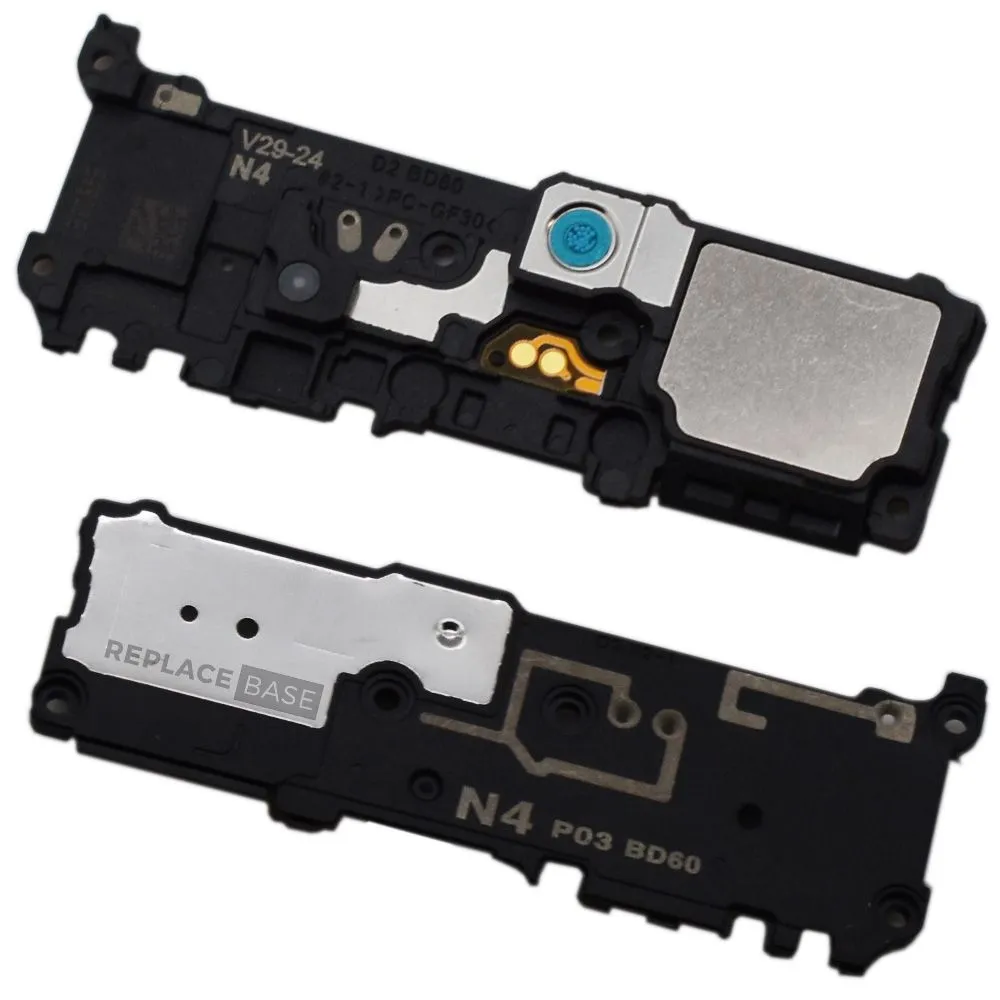
– Grab your trusty Phillips screwdriver and let’s get those five 4 mm screws off the loudspeaker! You got this!


Step 14


– Grab your trusty spudger and gently use the pointed end to unplug the main interconnect cable from the motherboard. You’ve got this!
– Next up, it’s time to disconnect the secondary interconnect cable from the motherboard. Easy peasy!
Tools Used


Step 16

– Let’s get started by removing the main interconnect cable. This is a crucial step, so take your time and make sure it’s done correctly. If you need help, you can always schedule a repair
Step 17


Hey there! Just a friendly reminder: the secondary interconnect cable is best left alone. It’s snugly attached to the side 5G mmWave antenna, and we don’t want any accidental mishaps. Keep up the great work!
– Gently fold the secondary interconnect cable away from the battery using a spudger or your fingers. It’s like giving the cable a little hug, but without the awkwardness! If you need help, you can always schedule a repair
Tools Used
Step 18

– Grab your trusty Phillips screwdriver and go to town on those four 4 mm screws holding the top plastic cover in place. You’ve got this!
Step 19


– Time to get started. Use a pair of tweezers to carefully pry the top plastic cover up and off your phone. If you need help, you can always schedule a repair
Tools Used
Step 20


– Grab your trusty spudger and gently use the pointed end to free the touch layer connector from the motherboard. It’s like giving it a little nudge to say, ‘Time to disconnect!’
– Now, let’s give the side button connector a break and disconnect it from the motherboard. Just a little tug and you’re on your way!
Tools Used
Step 21


– Time to get started! Use the point of a spudger to carefully pry up and disconnect the 5G mmWave antenna connector from the motherboard – it’s like freeing a tiny captive.
– Now, gently bend the cable away from the motherboard, making sure not to put too much stress on it. If you need help, you can always schedule a repair
Tools Used
Step 22


– Grab your spudger and use the pointy end to gently disconnect the S-Pen charging coil connector from the motherboard. It’s like a little dance!
Tools Used
Step 23


– Grab your trusty spudger and use its pointed end to gently pop that display cable off the motherboard. You’ve got this!
Tools Used
Step 24


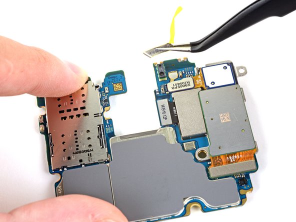
If the motherboard seems a bit stubborn, double-check that you’ve popped out the SIM tray.
– Time to get a grip on that motherboard. Use the pointed end of a spudger to carefully pry it up until you can get a good hold of it with your fingers.
– Now that you’ve got a grip, go ahead and remove the motherboard. If you need help, you can always schedule a repair
Tools Used
Step 25
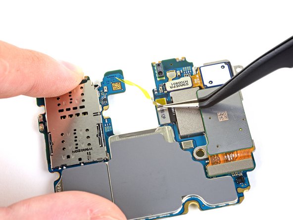

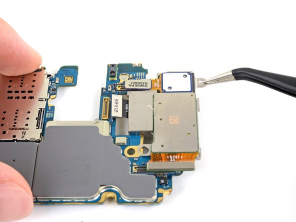
– Time to get up close and personal with that middle camera connector. Use a trusty pair of tweezers to gently remove the small piece of tape covering it. If you need help, you can always schedule a repair
Tools Used
Step 26
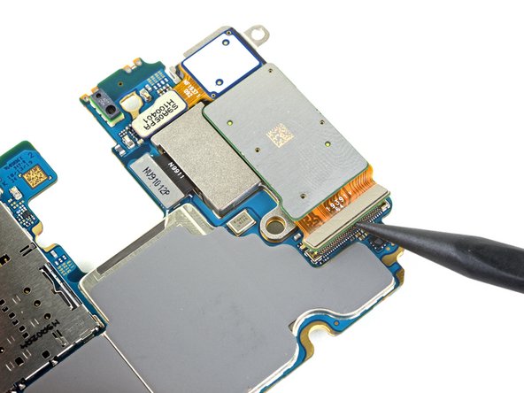

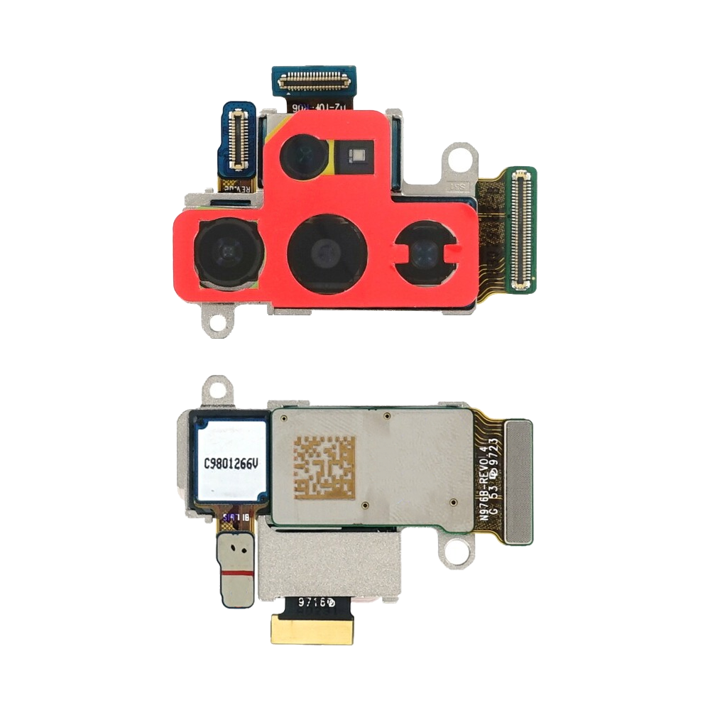
– Time to get started – use the pointed end of a spudger to carefully disconnect the bottom camera connector.
– Next up, disconnect the middle camera connector. If you need help, you can always schedule a repair
Tools Used
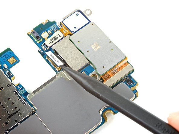
Step 27


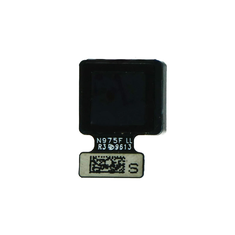
– Now it’s time to disconnect the top camera connector – use the pointed end of a spudger to gently pry it loose. If you need help, you can always schedule a repair
Tools Used
Step 28
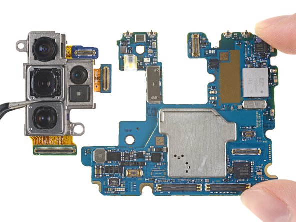

– Grab a trusty pair of tweezers or just your fingers to gently lift out the rear camera module. You’ve got this!
Tools Used