Samsung Galaxy Note10 Rear Camera Replacement Guide
Duration: 45 minutes
Steps: 25 Steps
Ready to give your Samsung Galaxy Note10 a little makeover? Follow this guide to easily take out or swap the rear camera module. If you need help, you can always schedule a repair.
Step 1

Make sure to power down your phone completely before diving into disassembly.
Hey there, techie! You can also use a hair dryer, heat gun, or hot plate to warm things up. Just be careful not to roast your phone—the display and internal battery are sensitive to heat. If you need help, you can always schedule a repair.
– Grab your trusty iOpener and give the left edge of the back panel a nice warm hug for about a minute.
Tools Used

Step 2


If your back glass is looking like a jigsaw puzzle, don’t worry! A quick fix is to slap on a layer of clear packing tape—it might just help that suction cup stick like it’s meant to be there. In a pinch, super strong tape can take the place of the suction cup altogether. And if you’re really in a bind, a little superglue can anchor that suction cup to the cracked panel. You’ve got this!
Now, if your phone is a little on the older side, getting that glass off may be a bit of a challenge. If you’re struggling, don’t be afraid to apply a little more heat to the edge and give it another go. You’re one step closer!
– Grab a suction cup and stick it to the warm edge of the back panel, getting as close to the edge as you can.
– Give that suction cup a solid pull with steady strength to open up a little gap between the back panel and the frame.
– Slide the tip of an opening pick into that gap you’ve just created.
Step 3


Alright, cool cat, just a heads up! Don’t go sticking that opening pick too deep into the phone. You might end up hurting some of those delicate bits and pieces inside. Keep it chill and slide it in halfway, and we’ll be good to go!
– Gently glide the opening pick along the left edge, making your way to the bottom left corner to deftly cut through that adhesive.
– Keep the pick snugly in the bottom left corner to stop the adhesive from getting all clingy again.
Step 4


– Now it’s time to bring in some extra help – insert a second opening pick and gently slide it across the left side, making your way towards the top left corner. This will help you slice through the adhesive with ease.
– Leave that pick right where it is, nestled in the top left corner, to keep the adhesive from re-sealing and making your job more difficult. If you need help, you can always schedule a repair
Step 5

– Grab your trusty iOpener and heat up that top edge of the phone for a minute. It’s gonna be a warm welcome for the phone’s guts!
Tools Used
Step 6


– Let’s get this phone open! First, slide a third opening pick into the gap along the top edge of the phone.
– Now, slide the pick to the top right corner, gently cutting through the adhesive holding it shut.
– Leave the pick in place in the top right corner, keeping the adhesive from sealing back up. You got this!
Step 7

– Grab your trusty iOpener and give it a warm hug on the right edge of the phone for a solid minute. You’re doing great!
Tools Used
Step 8


As you make your way to the bottom edge of the phone, the back panel will start to separate. It’s like magic!
– Pop in that fourth and final opening pick into the gap on the right side of your phone, and slide it down towards the bottom right corner to cut through that pesky adhesive.
– Now, take that opening pick and gently glide it back and forth around the entire edge of the phone to free any stubborn adhesive that might have been missed. If you encounter some extra-stubborn spots, don’t hesitate to give it a little heat!
Step 9


– Gently pop off the back panel and set it aside like a pro.
Step 10

– Alright, let’s get those screws out! Use a Phillips screwdriver to remove the five 4 mm screws holding the wireless charging coil in place. If you need help, you can always schedule a repair


Step 13


– Grab your trusty spudger and gently use its pointed end to unplug the wireless charging coil connector from the motherboard. You’ve got this!
Tools Used
Step 14


The wireless charging coil is gently held in place with a bit of light adhesive, making it super easy to work with!
– Gently tilt the metal shield upward so you can easily grab it with your fingers.
– Carefully peel the wireless charging coil away from the device, just like taking off a cozy blanket.
– Time to say goodbye! Remove the wireless charging coil and set it aside.
Step 15

– Grab your trusty Phillips screwdriver and get ready to tackle those five 4 mm screws holding the loudspeaker in place. You’ve got this!


Step 17
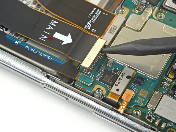


– Grab your trusty spudger and gently use the pointed end to unplug the main interconnect cable from the motherboard. You’ve got this!
– Next up, it’s time to disconnect the secondary interconnect cable from the motherboard. Just a little tug and you’re on your way!
Tools Used
Step 18


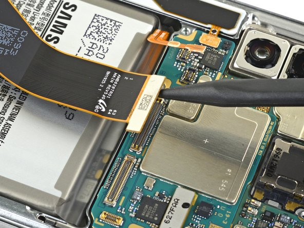
– Now, let’s give those cables a little break! Grab your trusty spudger and gently disconnect the main interconnect cable from the daughterboard.
– Don’t forget about the secondary interconnect cable! Give it a little nudge with the spudger and disconnect it from the daughterboard too.
Tools Used
Step 19


– Disconnect both interconnect cables with care.
Step 20

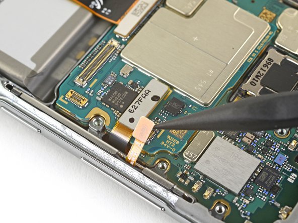
– Grab the pointed end of your trusty spudger and gently pry away the display cable from the motherboard. You’ve got this!
Tools Used
Step 21


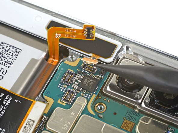
– Grab your trusty spudger and gently use its pointed end to pop off the side button connector from the motherboard. Easy peasy!
– Next up, let’s disconnect the touch layer connector from the motherboard. You’re doing great!
Tools Used
Step 22

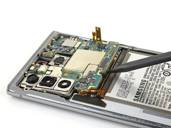
– Grab your spudger, the pointed end, and gently disconnect the S-Pen charging coil connector from the motherboard. It’s like giving the connector a little high five! Don’t worry, it’s a super easy step. If you need help, you can always schedule a repair
Tools Used
Step 23

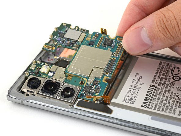
– Grab that spudger and use its pointy end to gently lift the motherboard just enough so you can get a good grip on it with your fingers.
– Now, go ahead and remove the motherboard!
Tools Used
Step 24
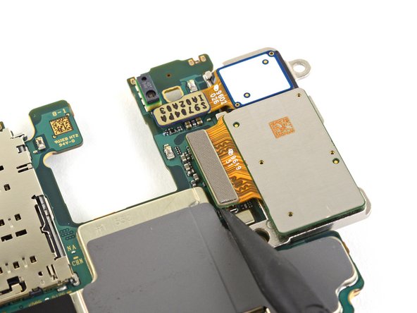
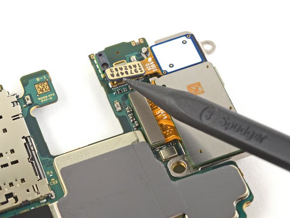

– Let’s gently unplug the top camera connector from the motherboard using the pointy end of a spudger.
– Now, give that bottom camera connector the same treatment!
Tools Used
Step 25

– Time to say goodbye to that old camera module! Carefully remove it, and don’t worry, we’re here to help every step of the way. If you need a helping hand, you can always schedule a repair.