DIY Samsung Galaxy Note9 Rear Camera Replacement Guide
Duration: 45 minutes
Steps: 33 Steps
Get ready to give your Samsung Galaxy Note9 a brand new rear camera. This step-by-step repair guide from Salvation Repair will walk you through the process. If you need help, you can always schedule a repair.
Step 1


– Grab your trusty SIM card eject tool and slide it straight into the little hole on the SIM card tray.
– Give it a gentle press to pop that SIM card tray out like a pro.
Tools Used

Step 2

The SIM card will pop right out of the tray with ease!
– Pop out that SIM card tray like a pro! You’ve got this!


Step 4


Hang in there, buddy! If the adhesive is being stubborn, try a little more heat. But be careful, you don’t want to go too crazy and crack the glass. If you’re feeling a little lost, you can always schedule a repair.
If your glass is looking like it’s been through a rough day, don’t fret! Just wrap it up in some packing tape to give the suction cup a solid grip. You’ve got this!
– Grab your trusty suction handle and give the back cover a big hug.
– Now, gently lift that handle to create a teeny tiny gap between the back cover and the phone’s frame.
– Slide an opening pick into that gap – just enough to make a friend with the inside.
Tools Used

Step 5

If the adhesive gets tough, don’t force it—just add some more heat, my friend!
– Alright, there’s a bit more sticky stuff along the top and around the camera than the rest of the phone. Don’t worry, it’s all part of the plan!
– Now, get ready to carefully cut around the left edge near the fingerprint sensor. Be super gentle here, you don’t wanna nick the ribbon cable inside. Take your time! If you need help, you can always schedule a repair
Step 6


Hey there! When using the pick near the fingerprint sensor or cameras, don’t go crazy and jam it in all the way. Just a little peek is all you need. Go too deep and you might accidentally make friends with the internal components. 😉 If you need help, you can always schedule a repair.
– Begin at the center and gently slice through the adhesive vertically along the right side using an opening pick.
Step 7


Watch out near the corners, as the glass is super fragile. If the adhesive gets a bit stubborn, feel free to add more heat anytime!
– Pop an opening pick into the upper-right corner to give yourself a little wiggle room.
– Grab another opening pick and gently slice through the adhesive around the bottom-right corner.
– Keep that opening pick snugly in place while you work your magic!
Step 8

– Grab your trusty heat gun, hair dryer, or a cozy heated iOpener and warm up the left side of the rear panel for about three minutes. This will help loosen that stubborn adhesive lurking underneath. Remember, a little heat goes a long way!
Tools Used
Step 9


Hang loose around the corners – that’s where the glass is a little more sensitive.
Don’t get too comfy with that opening pick on the left edge near the fingerprint sensor, you might bump into a ribbon cable. If you need help, you can always schedule a repair
Don’t worry if your opening picks fall out as you separate the back cover – it’s all part of the process. If you need help, you can always schedule a repair
– Let’s get started by inserting an opening pick into the lower-left corner of the rear panel – easy does it!
– Now, grab another opening pick and carefully cut the adhesive along the left edge of the rear panel. If you need help, you can always schedule a repair
Step 10


Grab your trusty iOpener, hair dryer, or heat gun and give it a little love where you’re slicing through that adhesive. A bit more warmth can work wonders!
– Now it’s time to get a little tricky – use that opening pick you inserted to carefully slice through the adhesive around the upper-left corner of the rear panel. Take your time, you’re doing great!
– Almost there! Use your pick to cut through the last bit of adhesive along the top of the phone. If you need help, you can always schedule a repair
Tools Used
Step 11


Be careful not to pull out the fingerprint sensor ribbon cable just yet, let’s take it one step at a time.
The fingerprint sensor cover might stick to the midframe, but don’t worry, it’s an easy fix. If you need help, you can always schedule a repair
– Let’s start by getting the right side of the rear cover loose. It’s like a little dance move!
– Now, gently tilt the cover up along the left edge. You’ll see the fingerprint sensor ribbon cable, which is just waiting to say hello!
Step 12


– Now, let’s get that fingerprint sensor ribbon cable out of its socket! Grab your trusty spudger and use the tip to gently pry it up. It’s like giving it a little high-five, but with a tool instead of your hand.
Tools Used

Step 13

– Let’s get that back cover off!
– To put the back cover back on, first we gotta clean up a bit. You can use tweezers to pick off any remaining adhesive, then give the phone chassis a good scrub with some high-concentration isopropyl alcohol (at least 90%) and a lint-free cloth. That’ll make sure the surface is ready for new adhesive. Don’t worry about getting every last bit of old adhesive off, but make sure you remove the bigger chunks.
– Time for a test drive! Power up your phone and make sure everything is working fine before you get all glued up.
– Now, it’s time to apply the new adhesive to the back cover, and then carefully line up one edge of the glass with the phone chassis. Press the glass firmly onto the phone. You got this!
Tools Used

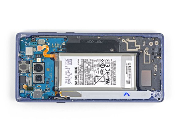
Step 14


– Let’s get started by removing the nine 4mm screws that hold the upper midframe in place – grab your trusty Phillips screwdriver and get to work. If you need help, you can always schedule a repair


Step 16


The adhesive might be taking a little nap, but don’t worry! You can totally use an opening pick to cut through it if you need to.
– Gently peel away the wireless charging coil from the battery, starting from the left side. Take your time—it’s like unwrapping a present!
– When it’s time to put things back together, start by snapping the midframe into place before you stick down that wireless charging coil. It’s all about getting the foundation right!
Step 17


– Grab your trusty spudger and gently pry apart that cheerful orange ribbon cable connecting the battery to the motherboard. You’ve got this!
Tools Used
Step 18

– Time to unscrew! Carefully take out the nine 4 mm Phillips screws holding the plastic cover next to the battery. You’ve got this!
Step 19

– Pop off the plastic cover next to the battery like you’re peeling a sticker off your favorite notebook.
Step 20


That lower midframe pops right in and out! Easy peasy, right?
– Time to get started – insert the tip of a spudger into the top of the lower midframe, it’s the first step to freeing it up.
– Gently pry the lower midframe out from the phone, taking your time to avoid any damage.
– You’re making progress – remove the lower midframe and set it aside, you’re one step closer to a fully functional device. If you need help, you can always schedule a repair
Tools Used
Step 21


– Time to get that front camera out – use the tip of a spudger to carefully pry the connector straight up and out of its socket. Take your time, it’s easier than you think!
– Now, grab those tweezers and gently remove the front camera. If you need help, you can always schedule a repair
Step 22


– Now, let’s gently disconnect that iris scanner from the motherboard. Grab your spudger and use the tip to carefully pry it loose.
– Time to say goodbye to the iris scanner! Use your trusty tweezers to remove it. You’re doing great!


Step 24


– Grab your trusty spudger and gently use its flat end to unhook that display cable from the motherboard. You’re doing great, keep it up!
Tools Used
Step 25


– Now, let’s gently disconnect that touchscreen cable from the motherboard. Using the flat end of your spudger, give it a little nudge. Easy peasy!
Tools Used
Step 26


– Grab your trusty spudger and gently nudge the flat end to disconnect the charging assembly from the motherboard. You’re almost there!
Tools Used
Step 27


– Time to remove those three little Phillips screws holding the motherboard in place! They’re 4 mm, just a heads up.
– Look for the triangles next to the screw holes – they’re like little guides to help you find the motherboard screw spots. Easy peasy!
Step 28


Buddy, be careful with those ribbon cables! Don’t yank that motherboard out if it’s caught on one. Keep ’em clear and you’ll be golden!
– Use a spudger to gently lift the motherboard from the upper-left corner. It’s like giving it a little high five, but with a tool!
– Carefully remove the motherboard. You got this! Remember, if you need help, you can always schedule a repair.
Tools Used
Step 29

– Now it’s time to carefully disconnect the rear camera – use the tip of a spudger to gently pry the connector straight up and out from the motherboard. If you need help, you can always schedule a repair
Tools Used
Step 30

– Grab a heat gun, a hair dryer, or a warm iOpener and give it a go on that rear camera area for about a minute. This will help soften up the sticky stuff holding the camera in place, making your repair a breeze! Remember, if you need help, you can always schedule a repair.
Tools Used
Step 31

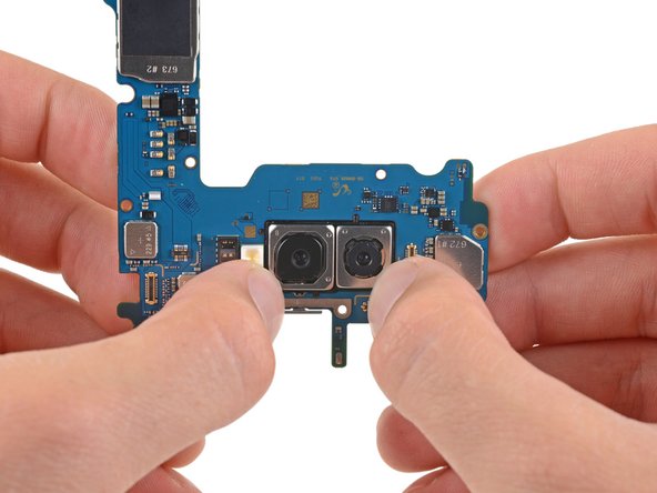
For your rear camera’s sake, steer clear of the lenses! This means don’t press ’em straight, y’know what I mean?
– Gently lift the motherboard with care.
– Using your thumbnails, nudge those metal bezels to loosen the rear camera from the motherboard.
– Pause when you notice the rear camera starting to come away from the motherboard. No need to completely remove it just yet!
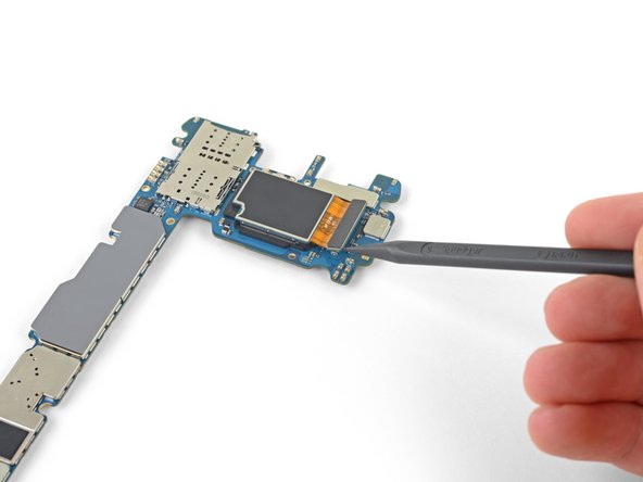
Step 32
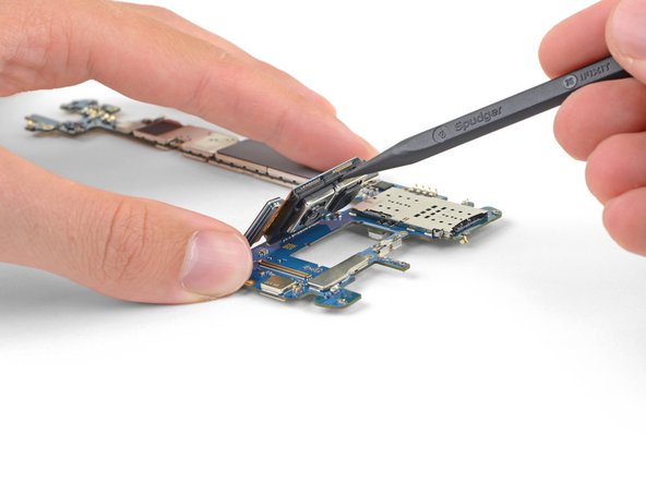

– Gently slide the flat end of your spudger into the tiny gap between the rear camera and the motherboard. No pressure, just a light touch!
– Give it a little lift to cheerfully detach the rear camera from its cozy spot on the motherboard.
Tools Used
Step 33

– Time to give that rear camera some freedom! Gently remove it from the motherboard. If you need help, you can always schedule a repair