How to Replace Samsung Galaxy Note II Display – DIY Guide
Duration: 45 minutes
Steps: 36 Steps
Ready to give your Samsung Galaxy Note II a fresh new look? This guide will walk you through the steps to swap out that front panel display assembly like a pro! If you need help, you can always schedule a repair.
Step 1


– Let’s get started by carefully pulling out the stylus from its midframe slot. Simply grasp the end of the stylus and gently remove it.
Step 2


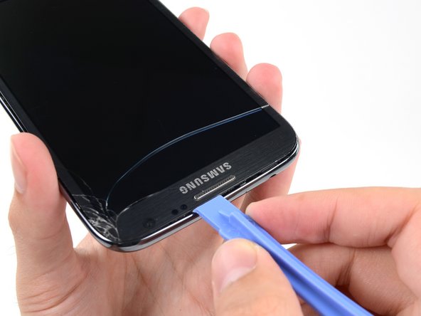
– Let’s get started by carefully prying with a plastic opening tool, or even your trusty fingernail, in the divot to the left of the rear-facing camera – it’s located near the power button. If you need help, you can always schedule a repair
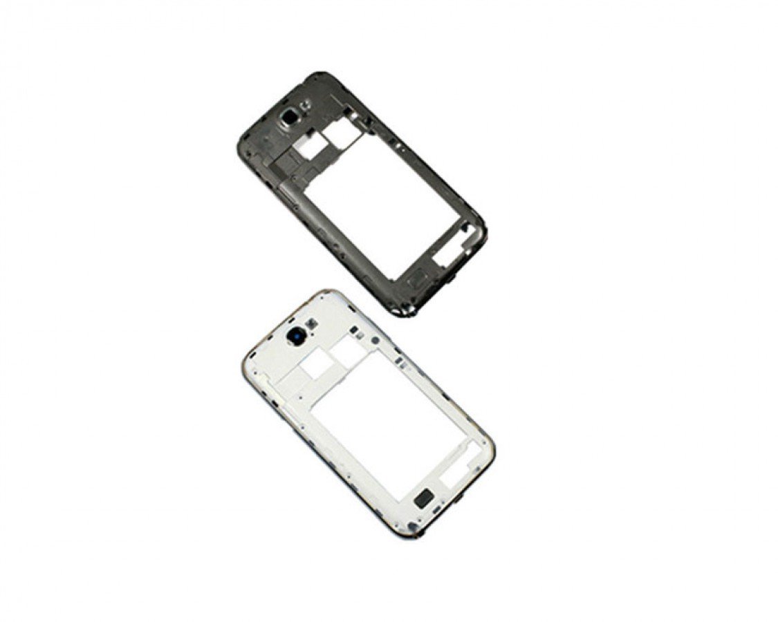
Step 3


– Grab the rear case by the corner closest to the little groove and gently lift it off the phone. Let’s get this show on the road!
Step 4


– If you have an SD card inserted, you can gently nudge it out by pressing the flat end of a spudger, or even your fingernail, on the microSD card until you hear a click. It’s like giving it a little push!
– Once you hear that click, the card will pop out of its slot!
– Now you can remove the microSD card. You’re doing great!
– To put it back in, just slide the microSD card into its slot until it clicks in place. Easy peasy!
Tools Used

Step 5


– Now, grab your trusty plastic opening tool (or even your finger if you’re feeling bold!) and gently slide it into the notch on the battery compartment. Give that battery a little lift, and she’ll pop right out. Easy peasy!
Step 6

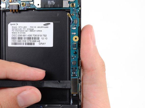
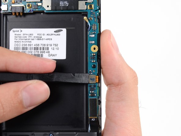
– Let’s get started by removing the battery from the midframe. This is a crucial step, so take your time and make sure it’s done correctly. If you need help, you can always schedule a repair
Step 7

– Let’s get started by removing the eleven 4.0 mm Phillips #00 screws that hold the midframe in place on the display assembly. If you need help, you can always schedule a repair
Step 8


– Let’s get this party started! Gently slide your plastic opening tool between the midframe and front panel assembly on the side of the phone. You got this!
– Now, just slide that tool down the seam. You’re doing great!
Step 9


– Now, keep sliding that plastic opening tool along the seam to make progress with your repair. If you need help, you can always schedule a repair
Step 10


– Gently work your way around the corner with a plastic opening tool – it’s time to set that phone free.
Step 11

– Let’s get started by carefully prying along the top of the phone with a plastic opening tool. If you need help, you can always schedule a repair
Step 12


– Time to free that corner! Push the plastic opening tool down to gently separate the midframe from the display assembly. Don’t worry, it’s just a little wiggle and it’ll come loose. If you need help, you can always schedule a repair.
Step 13


– First, let’s get started by freeing the clips along the power button side of the phone – it’s an easy step to get you moving.
– Lastly, carefully release the two clips along the top and bottom edge of the battery compartment. If you need help, you can always schedule a repair
Step 14


– Alrighty, it’s time to lift the display assembly out of the midframe. It’s a breeze – just make sure to be gentle with those delicate components. If you need help, you can always schedule a repair!
Step 15


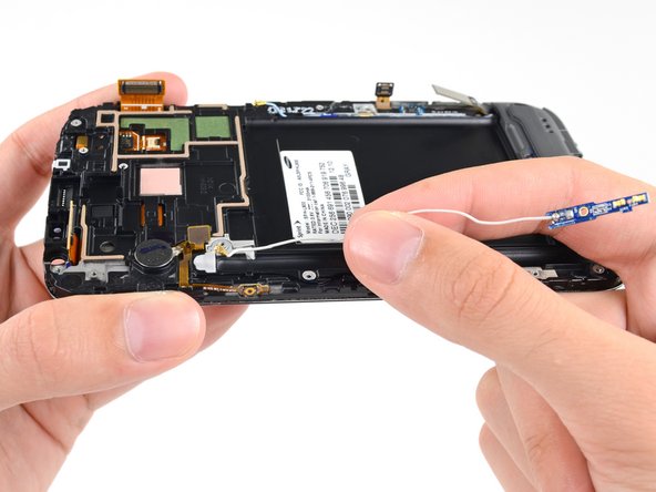
– Let’s get started – use a spudger to carefully disconnect the vibrator/power button assembly cable connector.
– Next, locate and disconnect the antenna cable connector to move forward with your repair.
– Now, gently disconnect the display cable connector to make some progress on your device’s repair. If you need help, you can always schedule a repair
Tools Used
Step 16


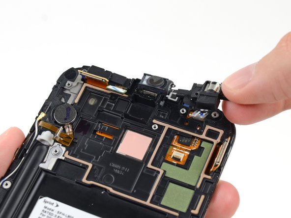
– Time to unplug the front-facing camera cable connector. Let’s keep that camera safe!
– Next up, gently disconnect the headphone jack cable connector. Music to our ears, right?
– Now, it’s the digitizer cable connector’s turn to be unplugged. You’re doing great!
Step 17

– Let’s get those cables unplugged! First, use your trusty spudger to gently disconnect the antenna cable connector from the motherboard. It’s like a little dance, just slide it off.
– Now, let’s tackle that soft button cable connector. Give it a little wiggle and it’ll come right off.
– Finally, time to disconnect the USB board cable connector. Easy peasy, just pull it apart.
Tools Used
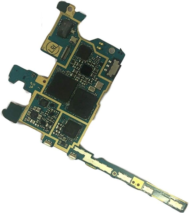
Step 18

– Unscrew the 3 mm Phillips #00 screw that’s holding the motherboard snugly to the display assembly. You’ve got this!
Step 19


Alright, you’re almost there! Just grab the motherboard by its edges (you know, like a pro) and carefully pull it out of the display assembly. Make sure you’re not snagging any cables along the way. If you need help, you can always schedule a repair.
– Now it’s time to carefully take out the motherboard. Take your time and be gentle, we’ve got this! If you need help, you can always schedule a repair
Step 20

– Let’s get this party started! Remove that little 3 mm Phillips #00 screw holding the headphone jack assembly to the display assembly. You got this!
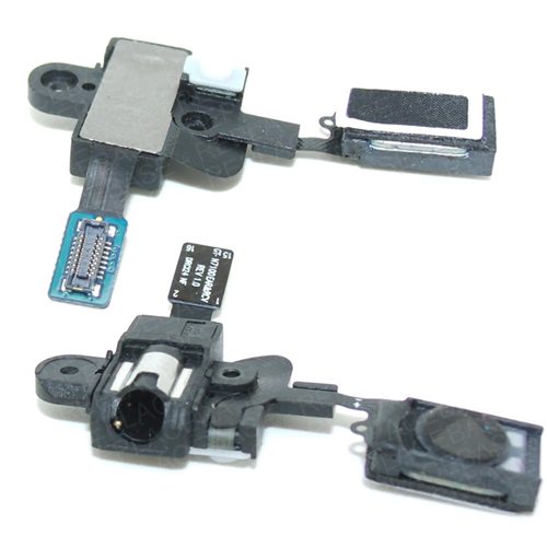
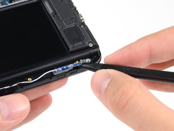
Step 21

– Gently grab the headphone jack part of the assembly and lift it out of its cozy spot in the display assembly.
Step 22

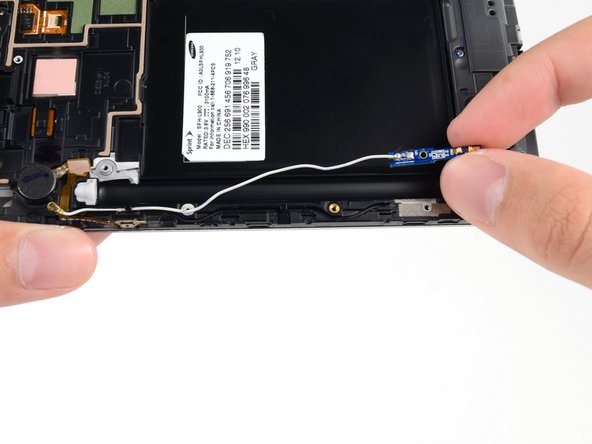
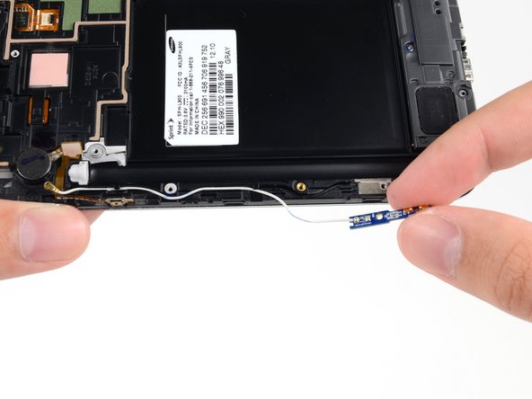
Twisting or yanking the cable unevenly can wreck it. Take your time and carefully extract the assembly. If you need help, you can always schedule a repair.
– Carefully lift the headphone jack straight up, avoiding any twisting of the cable, to free the earpiece speaker from its snug little home.
Step 23

– Let’s get this party started! First things first, remove that little 3mm Phillips #00 screw holding the front-facing camera bracket in place. Don’t worry, it’s easy peasy.
Step 24

– Let’s get started by removing the front-facing camera bracket. This is a crucial step, so take your time and make sure it’s done correctly. If you need help, you can always schedule a repair
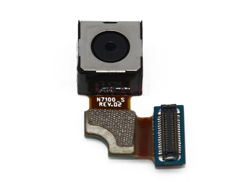
Step 25

– Take out the front-facing camera with care.
Step 26

– Unscrew the 3 mm Phillips #00 screw that’s holding the antenna board snug against the display assembly. You’ve got this!
Step 27

– Let’s get that antenna board free! Use your spudger to gently lift it away from the display assembly. Just a little wiggle and it’ll pop right off. If you’re not feeling super confident, you can always schedule a repair.
Tools Used
Step 28

– Carefully guide the antenna cable out of its groove in the display assembly. Let’s keep things smooth and easy!
Step 29

– First, carefully remove the antenna cable from the display assembly – it’s a breeze.
– When putting everything back together, make sure to install the USB board and attach the antenna connector before routing it into the channel. This ensures the antenna cable connectors are properly in place. If you need help, you can always schedule a repair
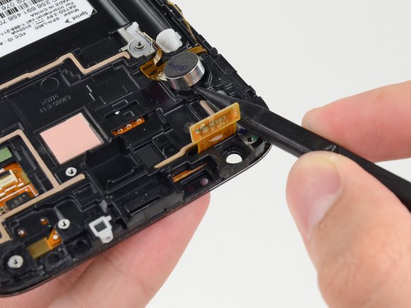
Step 30

Hey there! Just a friendly reminder: don’t try to take out the vibrator completely since it’s still connected to the vibrator/power button assembly. Keep it together for a smooth repair journey!
– Now, let’s gently free that little vibration motor! Use the tip of your spudger to carefully pry it loose from the sticky grip of the display assembly. Take your time and be careful, we don’t want any drama here. If you need help, you can always schedule a repair
Tools Used
Step 31

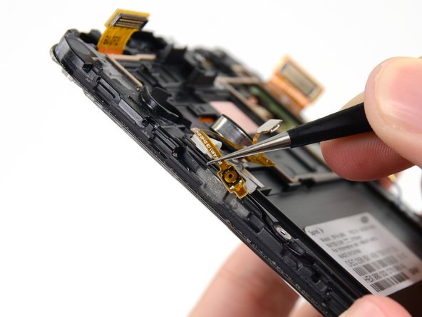
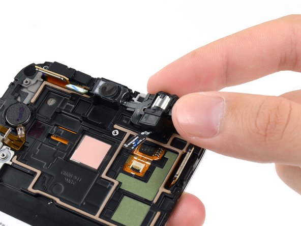
– Grab your trusty tweezers and gently pry the power button away from the sticky adhesive that’s holding it to the display assembly. You’ve got this!
– Now, carefully lift out the vibrator/power button assembly from the display assembly. Easy peasy!
Tools Used

Step 32

– Let’s get started by removing the 3 mm Phillips #00 screw from the speaker enclosure. If you need help, you can always schedule a repair
Step 33

– Let’s get started by removing the speaker enclosure. This is the first step in giving your device a brand new sound system. If you need help, you can always schedule a repair

Step 35
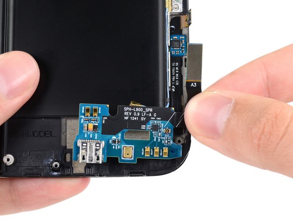
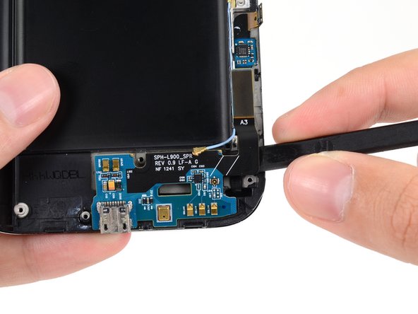

Okay, here’s the deal, to avoid any drama (like bending that USB board!), slide the spudger in at a slight angle. You’ll be a pro in no time!
– Time to get this repair started – use the flat end of a spudger to carefully pry the USB board away from the display assembly.
– Now that it’s loose, go ahead and remove the USB board from the display assembly. If you need help, you can always schedule a repair
Tools Used
Step 36

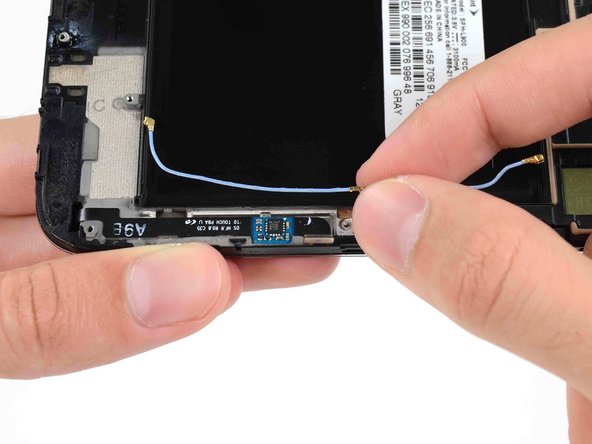
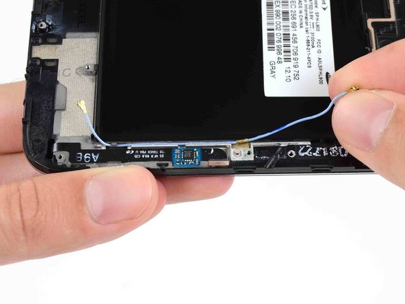
– Carefully unhook the antenna cable from its slot in the display assembly.
– Take out the antenna cable.