Samsung Galaxy S24 Plus Rear Cameras Replacement Guide
Duration: 45 minutes
Steps: 36 Steps
Hey there! This guide’s gonna help you swap out those rear cameras on your Samsung Galaxy S24+ like a pro. Don’t worry, it’s easier than you think. We’ll walk you through it step by step. If you need help, you can always schedule a repair.
Step 1


– First things first, let’s disconnect any cables hanging out of your phone. Give it some space!
– Next up, press and hold the side key along with the volume down button, then tap ‘Power off’ to send your phone into a well-deserved nap.
Step 2

If you’re feeling extra adventurous, you can also try using a hairdryer, heat gun, or hot plate to loosen things up. But be careful! Overheating your phone is a major no-no—it could fry the display or battery. If you’re feeling hesitant, you can always schedule a repair with us. We’ll take care of it!
– Heat up an iOpener and place it on the right edge of the back cover for two minutes.
Tools Used


Step 3

If you’re having a tough time creating a gap, don’t sweat it! Just add a bit more heat to loosen up that sticky adhesive. And hey, be sure to check out the iOpener instructions to keep things from getting too toasty.
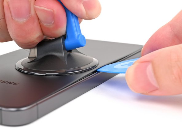
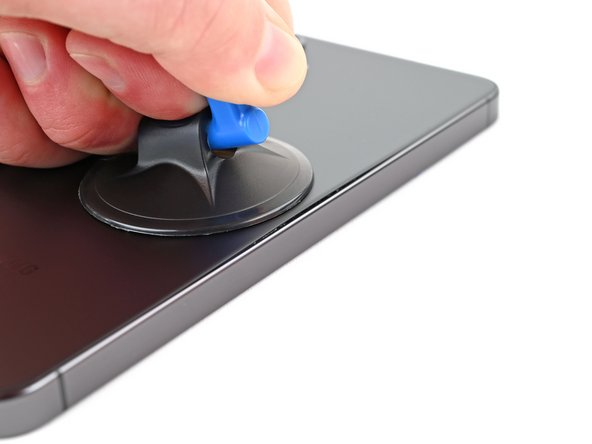
– Alright, time to get this party started! Grab your trusty suction handle and stick it to the back cover, aiming for the center of the right edge. Make sure it’s nice and secure.
– Now, give that suction handle a good pull! You want to create a little gap between the cover and the frame. Think of it like opening a door with a little help from your friend (the suction handle).
– Time to sneak in! Carefully insert an opening pick into the gap you just made. This is where the real fun begins.
Tools Used


Step 5

– Let’s get this party started! Warm up the back cover with a heated iOpener for about two minutes. This will make it easier to loosen things up.
Tools Used
Step 6


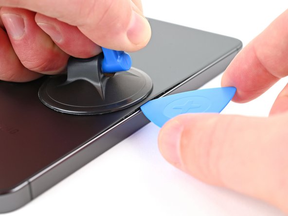
– Now, let’s get that bottom right corner separated! Give the opening pick a little spin to loosen up the adhesive. You got this!
Step 7

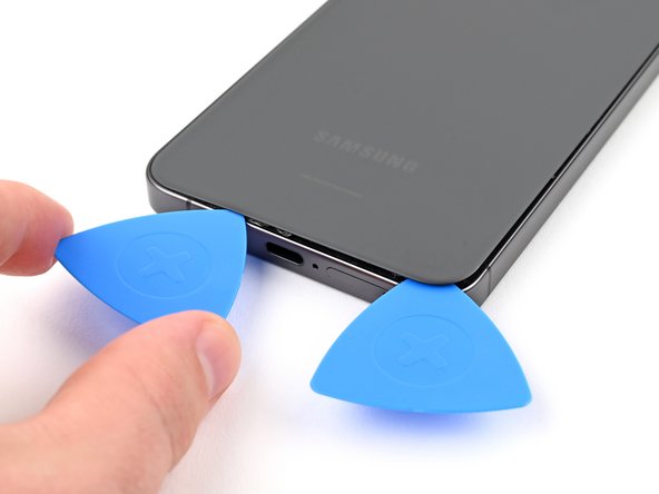
– Now it’s time to bring in some backup – insert a second pick at the bottom right corner to help loosen things up.
– Gently slide the opening pick over to the bottom left corner to break the adhesive’s hold.
– Leave that pick right where it is, in the bottom left corner, to keep the adhesive from sneaking back into place. If you need help, you can always schedule a repair
Step 8

– Warm up that trusty iOpener and gently press it against the left edge of the back cover for about two minutes. You’re doing great!
Tools Used
Step 9


– Twist the opening pick around the bottom left corner to peel back that adhesive like a pro!
Step 10


– Let’s get this party started! Insert a third opening pick at the bottom left corner.
– Now, slide the pick towards the top left corner, gently separating the adhesive.
– Leave the pick near the top left corner to keep that pesky adhesive from sealing itself back up. Don’t worry, we’ve got this!
Step 11

– Time to get this repair started. Apply a heated iOpener to the top edge of the back cover for about two minutes. If you need help, you can always schedule a repair
Tools Used
Step 12


– Now it’s time to get this repair started – gently rotate the opening pick around the top left corner to loosen the adhesive and get things moving.
Step 13


– Let’s loosen things up! Take your fourth opening pick and slide it into that top left corner.
– Slide the pick toward the top right corner, gently separating the adhesive. It’s like giving the phone a little hug, but with a tool!
– Keep that pick in place near the top right corner. You don’t want that adhesive getting cozy again, do you?
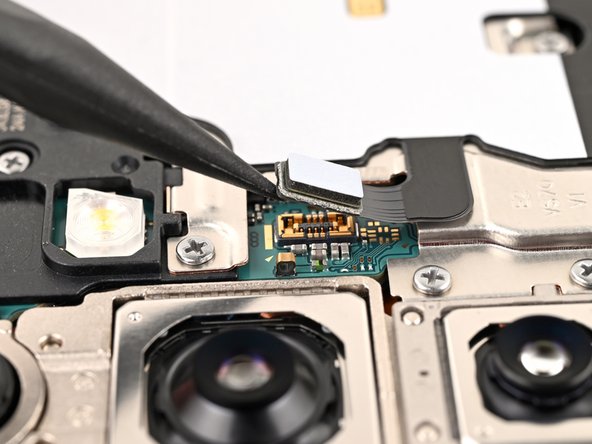
Step 14


You’ll find a little square of adhesive around the rear microphone, right above the flash. It’s like a tiny sticker that helps keep everything in place.
– Align the tip of your trusty opening pick with the flash.
– Gently slide the pick beneath the top edge of the back cover until you feel it catch on the adhesive.
– Continue to glide the pick down towards the bottom of the phone while carefully lifting the cover until it pops free from the sticky stuff.
Step 15


If you’re struggling to get the back cover off, use an opening pick to loosen up any sticky bits that might be holding it down.
Now’s the perfect time to power up your phone and make sure everything’s working like a charm before you button it all back up. Just remember to give your phone a power nap before you keep going.
You can always try to get that back cover adhesive back in place like a boss, but just remember – your phone won’t be waterproof after the repair, so you might want to keep it away from the pool. If you’re not sure what to do, you can always schedule a repair
– Start by popping off that back cover like a champ!
– Now, as you get ready to put everything back together:
– Break out those tweezers or just use your fingers to tackle any leftover adhesive on the back cover and the phone itself. If you’re having a tough time, a little heat or some isopropyl alcohol (at least 90%) along with a coffee filter or lint-free cloth can make it a breeze!
– And hey, if you’ve got custom-cut adhesives, don’t forget to check out the guide!
Tools Used


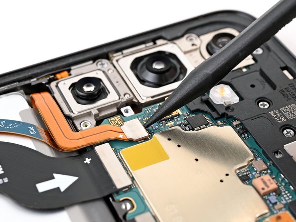
Step 16

Take a closer look at the board near each press connector – you’ll spot an arrow that shows you the best spot to pry it open. If you need help, you can always schedule a repair
– Time to get those nimble fingers working! Use a spudger to gently pry up and disconnect the wireless charging coil press connector from the motherboard.
– Now, let’s reconnect those connectors with a little finesse! Line up the connector carefully over its socket, and give it a little press with your fingertip—one side at a time—until it clicks into place. Don’t force it; just be patient. If things get tricky, reposition it and try again. You got this!
Tools Used

Step 17


– Grab your trusty Phillips screwdriver and remove the thirteen 3.5mm-long screws that hold the wireless charging coil and loudspeaker in place:
– You’ll find six screws securing the wireless charging coil – take those out first
– Next, remove the seven screws that keep the loudspeaker locked down. If you need help, you can always schedule a repair
Step 18


– Time to get started. Insert the point of a spudger into the notch at the top left corner of the loudspeaker – it’s marked with an arrow to help you out.
– Gently pry up to unclip the loudspeaker from the frame. If you need help, you can always schedule a repair
Tools Used
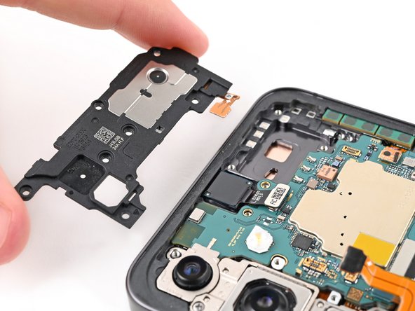
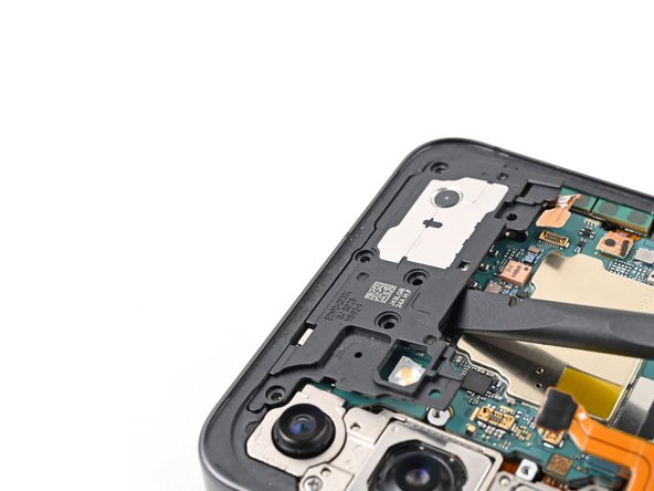
Step 19


– Give that loudspeaker a gentle lift with your fingers, separating it from the frame.
– Now, let’s detach the wireless charging coil and loudspeaker from the frame – they’re ready for a new adventure!
– Time to reassemble! Give the loudspeaker’s edges a little squeeze to clip it back into the frame before screwing it back in place. You’ve got this!
Step 20

– Let’s get that battery connector unplugged! Use a spudger to gently pry it up and disconnect it. If you need help, you can always schedule a repair.
Tools Used
Step 21


– Time to get those connectors unhooked! Use a spudger to carefully pry up and disconnect both interconnect cable press connectors from the daughterboard. Don’t worry, it’s just like unplugging a phone charger. If you need help, you can always schedule a repair.
Tools Used
Step 22


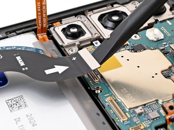
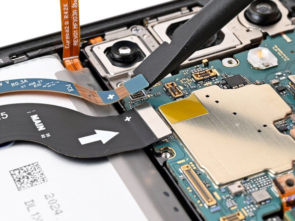
– Time to get connected – or rather, disconnected. Use a spudger to carefully pry up and release both interconnect cable press connectors from the motherboard. If you need help, you can always schedule a repair
Tools Used
Step 23


– Let’s get started by carefully removing the interconnect cables from your phone. Take your time and gently pull them out.
Step 24


– Grab your trusty spudger and gently wiggle it to lift up and disconnect that earpiece speaker press connector. You’ve got this!
Tools Used
Step 25


– Let’s get this earpiece speaker out! Grab your trusty Phillips screwdriver and give those five 3.5 mm screws a spin to loosen them up. You got this!
Step 26

– Gently slide the flat end of your spudger between the bottom edge of the earpiece speaker and the metal plate on the motherboard. You’re doing great!
– Twist that spudger like you mean it to unclip the earpiece speaker from the frame and pop it out. You’re making progress!
– When it’s time to put everything back together, start by inserting the top edge of the earpiece speaker into the frame before pressing down to clip it back in. You’ve got this!
Tools Used
Step 27

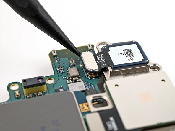
Hey, keep the spudger in its lane! It’s like the dance floor – stay on your designated area to avoid tripping over those tiny components. You know you’re gonna be a rockstar at this, though!
– Let’s get that upper antenna connector unplugged! Slide the tip of your trusty spudger under the top left corner of that connector.
– Now, gently pry it up and give it a little wiggle to disconnect the upper antenna connector from the motherboard. You’ve got this!
Tools Used
Step 28

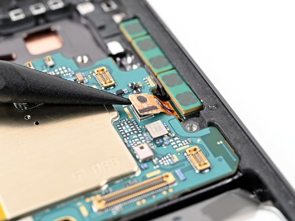
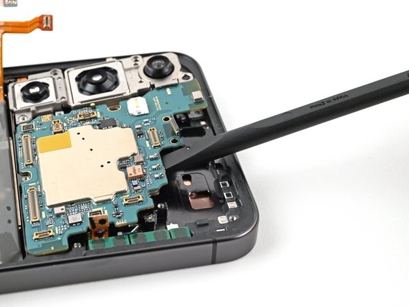
Be careful not to insert the spudger in any other spot, or you might accidentally damage those fancy surface-mounted components. If you need help, you can always schedule a repair
– Time to get started – carefully insert the tip of a spudger under the bottom right corner of the front camera press connector, making sure not to damage any surrounding components.
– Gently pry up and disconnect the front camera press connector from the motherboard. If you’re not feeling confident, don’t worry – you can always schedule a repair with Salvation Repair for some expert help.
Tools Used
Step 29

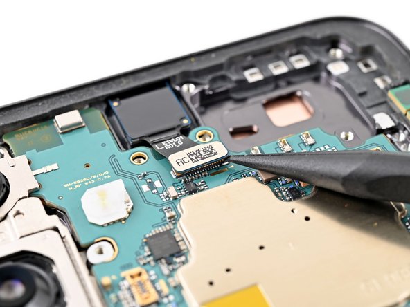
– Grab your trusty spudger and gently pry up those display and lower antenna cable connectors from the motherboard. It’s easier than it sounds, and you’ve got this!
Tools Used
Step 30

– Grab your trusty Phillips screwdriver and let’s tackle those two 3.5 mm-long screws holding the motherboard in place. You’ve got this!
Step 31

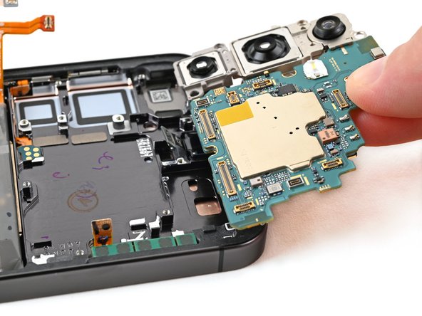
– Slide the flat end of a spudger between the top edge of the motherboard and the phone frame, right near the earpiece speaker cutout.
– Gently pry against the frame to lift the motherboard out of its slot. Go ahead and remove it!
– When you put things back together, make sure all the cables are out of the way before you drop that motherboard back into the frame.
Tools Used
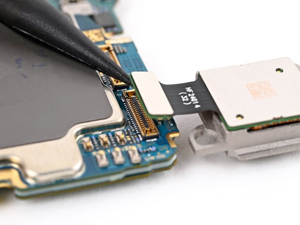
Step 32

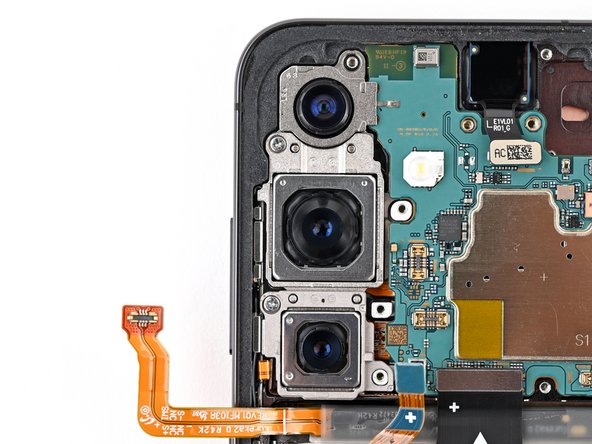
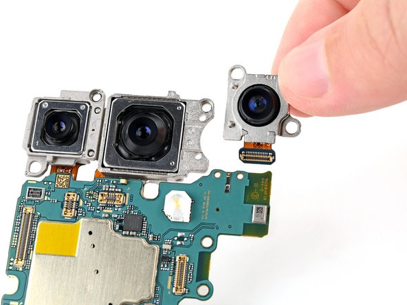
To tackle those three rear cameras, think of them as a little family stacked together. Start by gently removing the ultrawide camera first, then the main one, and finally, the telephoto. Easy peasy!
Remember, the ultrawide camera is the topmost member of this camera crew when it’s all set up.
– Flip that motherboard over, let’s give that rear camera connector a peek!
– Grab your trusty spudger and gently pry up that ultrawide camera connector. We’re going to give it a little break, just like you deserve after this repair!
Tools Used
Step 33

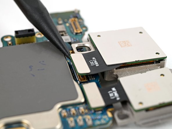
Alright, this ultrawide camera is a little sassy and held onto the motherboard with two metal pegs. Don’t worry, we’ve got this!
– Gently slide those pegs on the ultrawide camera out of their cozy spots on the motherboard to set it free.
Step 34

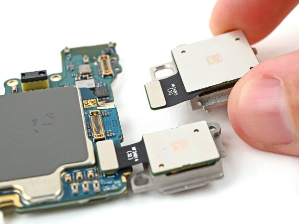
The main camera is located right in the center.
– Let’s free that camera! Use a spudger to gently pry up and disconnect the main camera press connector.
– Now that it’s unplugged, carefully lift the main camera off the motherboard. You got this!
Tools Used
Step 35

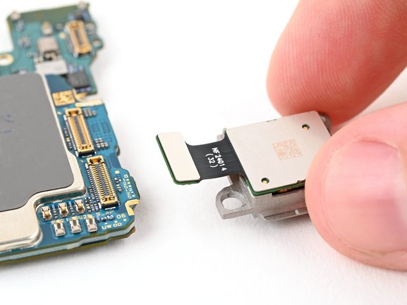
The telephoto camera is located at the bottom when it’s all put together and ready to snap those awesome pics!
– Let’s get started by using a spudger to carefully pry up and disconnect the telephoto camera press connector.
– Next, gently lift the telephoto camera off the motherboard and remove it – you’re making great progress!
– When it’s time to put everything back together, make sure to install the rear cameras in the correct order so they fit together seamlessly:
– Start with the Telephoto camera (it’s the small one with a metal back)
– Then add the Main camera (the large one with a metal back)
– Finally, install the Ultrawide camera (it’s the one with a plastic back) – you’re almost done!
– If you need help or get stuck along the way, don’t worry – you can always schedule a repair with Salvation Repair for some expert assistance.
Tools Used