Samsung Galaxy S23+ Motherboard Replacement Guide
Duration: 45 minutes
Steps: 37 Steps
Let’s swap out that motherboard and bring your Samsung Galaxy S23+ back to life! Heads up, though, the water resistance might not be the same after this swap. It all depends on how well you stick that back cover back on. But hey, no worries! You’ll get your device working again, and if you need help, you can always schedule a repair.
Step 1


Alright, buddy, let’s make sure your phone’s battery chills out a bit before we get started! Let that battery juice drop below 25%, and we’ll be good to go. A fully charged battery can be a bit of a safety hero, so we wanna make sure things are nice and calm. If you see a battery that’s looking a little puffy, it’s time to call in the pros. If you need help, you can always schedule a repair
– Let’s power down that phone, champ! Unplug all cables and give those side keys a squeeze with the volume down button. Then, select “Power off” to give your phone a little nap time.
Step 2

When using heat to loosen things up, remember that a hair dryer, heat gun, or hot plate can be your best friend – just be gentle and don’t overdo it. Your phone’s display and internal battery are sensitive to heat, so keep an eye on the temperature. If you need help, you can always schedule a repair
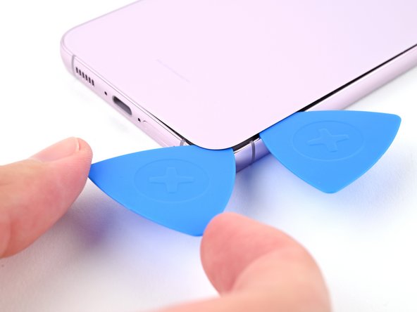
– Warm up your trusty iOpener and gently press it against the right edge of the back cover for a cozy two minutes to get that adhesive nice and soft.
Tools Used


Step 3


If you’re having a tough time making a gap, don’t sweat it! Just add a bit more heat to help loosen that adhesive up. Remember to check out the iOpener instructions to keep things from getting too hot to handle.
– Grab your trusty suction handle and stick it to the back cover. Aim for the center of the right edge – right smack dab in the middle!
– Now, pull up on that handle with some serious strength. We’re talkin’ steady, consistent force to create a little space between the cover and the frame.
– With that gap open, slide in your opening pick like a pro. You’re gettin’ this!
Tools Used

Step 4


– Slide that pick back and forth along the right edge, like a little dance, to separate the adhesive.
– Leave the pick hanging out near the bottom right corner, so that adhesive doesn’t get any funny ideas about sealing itself back up. If you need help, you can always schedule a repair
Step 5

– Time to warm things up! Apply a heated iOpener to the bottom edge of the back cover for two minutes. This will help loosen the adhesive holding it in place.
Tools Used
Step 6

– Now it’s time to bring in some extra help – insert a second pick at the bottom right corner to get this repair going.
– Gently rotate the opening pick around the bottom right corner to loosen the adhesive and make progress on your repair. If you need help, you can always schedule a repair
Step 7


– Slide the opening pick to the bottom left corner to get that adhesive separated. You’re doing great!
– Leave the pick in that corner to keep the adhesive from sticking back together. You’re almost there!
Step 8

– Time to get this repair started. Apply a heated iOpener to the left edge of the back cover for about two minutes. If you need help, you can always schedule a repair
Tools Used
Step 9


– Now it’s time to get this repair started – gently rotate the opening pick around the bottom left corner to loosen the adhesive and get things moving.
Step 10


– Hey there, let’s rock this corner! Slide in a cool third pick at the bottom left, okay?
– Now, rock n’ roll your pick up towards that top left corner. Time to separate those adhesive buddies!
– Don’t forget, leave your trusty pick in that top corner. We don’t want those adhesives closing the door on us, right?
Step 11

– Let’s get this party started! Grab an iOpener, heat it up, and give the top edge of that back cover a nice, two-minute warm-up. It’s like a spa day for your phone!
Tools Used
Step 12


– Let’s get this party started! Insert a fourth opening pick at the top left corner.
– Now, we’re gonna rotate it around the top left corner to separate the adhesive. You got this!
Step 13


– Slide your opening pick to the top right corner to get that adhesive parting like the Red Sea!
– Leave the pick in the top right corner to stop the adhesive from getting cozy and sticking back together. If you need help, you can always schedule a repair
Step 14


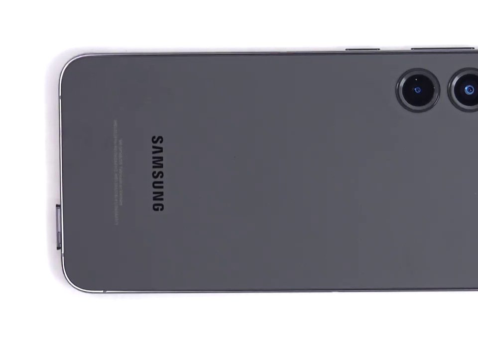
Hey, be careful around those rear cameras. Don’t get too close with your pick, you don’t want to accidentally scratch them! If you need help, you can always schedule a repair.
There’s a little leftover adhesive snugly hiding right beneath the flash.
Keep an eye out, you should be able to spot the opening pick peeking through the flash cutout.
– Let’s get started by aligning the tip of your opening pick with the flash cutout – it’s the perfect spot to begin.
– Gently slide the opening pick under the top of the back cover until you feel it catch on the adhesive. Don’t worry, it’s supposed to do that!
– Keep sliding the pick down toward the bottom of the phone. You’ll know you’re making progress when the adhesive starts to release from the back cover. If you need help, you can always schedule a repair
Step 15


If that cover is still stuck to the frame, don’t worry! Just slide an opening pick around the edges until it pops right off. You got this!
– Start by gently prying off the back cover—it’s like peeling a banana, but way more rewarding!
– Now, during the reassembly phase:
– Here’s a pro tip: power on your device and check that everything’s working before sealing it up tight. Just remember to switch it off completely before diving back in.
– Got some stubborn adhesive bits hanging around? Use tweezers or your fingers to remove them. If they’re being particularly clingy, a bit of heat and some isopropyl alcohol (90% or higher) should do the trick.
– Using custom-cut adhesives? Follow this guide for a flawless fit.
– If double-sided tape is your adhesive of choice, check out this guide for some handy tips.
Tools Used


Step 16


– Time to get that wireless charging coil press connector disconnected from the motherboard. Use the pointy end of your trusty spudger to gently pry it up and set it free.
– Re-attaching the press connectors is a breeze. Just carefully line them up and press down on one side until you hear that satisfying click. Then, repeat the process on the other side. Remember, don’t press down on the middle or you might end up bending those pins and causing some damage. If you need help, you can always schedule a repair with the pros at Salvation Repair.
Tools Used

Step 17


– Time to get that NFC antenna press connector disconnected. Use the point of a spudger to carefully pry it up and release it. If you need help, you can always schedule a repair
Tools Used
Step 18


– Grab your trusty Phillips screwdriver and remove the thirteen 3.5mm-long screws that hold the wireless charging coil and loudspeaker in place:
– You’ll find six screws securing the wireless charging coil – take those out first
– Next, remove the seven screws that keep the loudspeaker locked down. If you need help, you can always schedule a repair


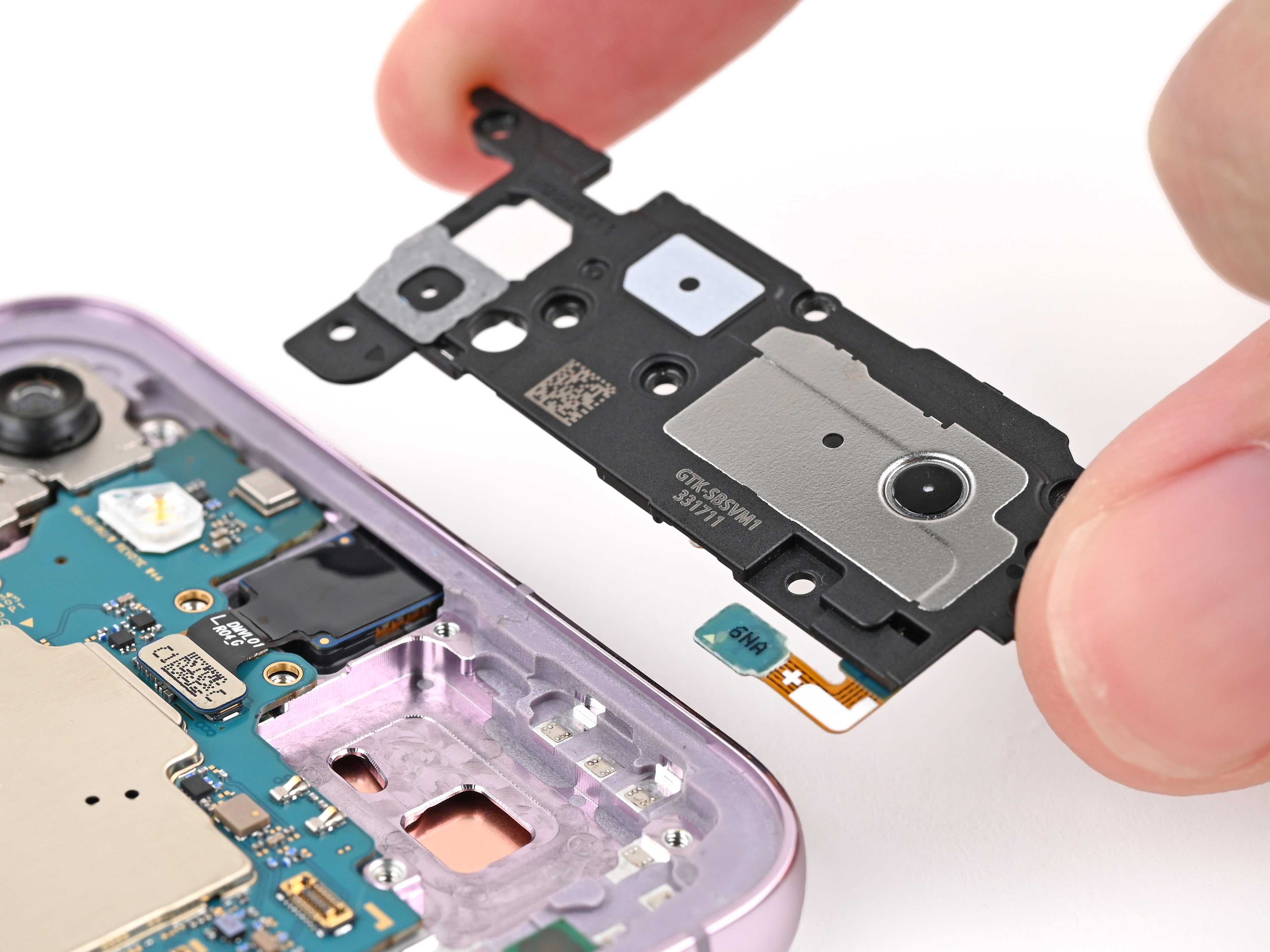
Step 20
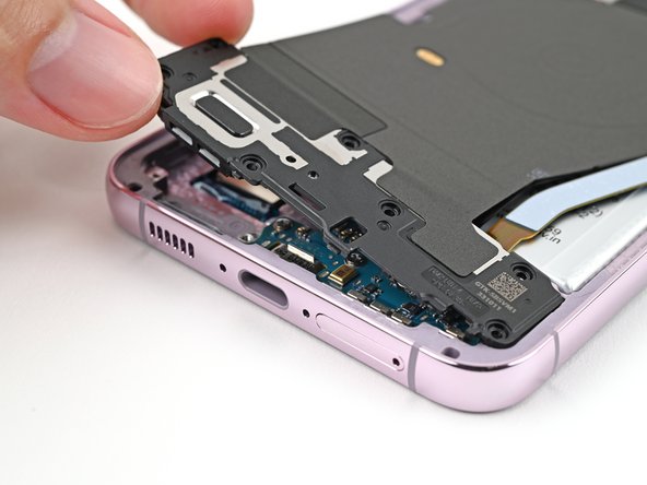

– Gently lift the loudspeaker away from the frame using your fingers—let it break free!
– Carefully take out the wireless charging coil along with the loudspeaker from the frame.
– When putting it all back together, give a little press around the edges of the loudspeaker to snap it snugly into the frame.


Step 22


– Grab your trusty spudger and gently nudge up the earpiece speaker press connector to disconnect it. You’re doing great!
Tools Used
Step 23


– Let’s get started by removing the five 3.5mm-long screws that hold the earpiece speaker in place – just grab a Phillips screwdriver and you’re all set. If you need help, you can always schedule a repair
Step 24


Be careful not to insert your spudger in the wrong spot, or you might accidentally dislodge some of the phone’s delicate surface-mounted components. If you need help, you can always schedule a repair
– Alrighty, friends! Let’s rock this repair journey together. Step 1: Gently slide that trusty spudger in between those handy dandy speaker and motherboard parts. Twist and ta-da! Your speaker is now free! For reassembly, just pop that speaker back in the wrong way, then smoosh it down and clip it. Boom! You did it! Need help at any stage? No worries! You can always schedule a repair with the awesome folks at Salvation Repair.
Tools Used
Step 25


– Now, let’s take a peek at those cables connecting the daughterboard. Gently use your trusty spudger to separate the primary and secondary interconnect cable press connectors. You got this!
Tools Used
Step 26

– Now, let’s do a little dance with those primary and secondary interconnect cable connectors on the motherboard. Repeat the previous step for those guys, too!
Step 27


– Let’s disconnect those interconnect cables. It’s like giving the device a break from its busy day!
Step 28


This connector is surrounded by some pretty delicate components. So, if you’re prying on the connector, be careful not to accidentally bump those little guys! They can be easily knocked loose. If you’re not sure, you can always schedule a repair.
– Carefully slide the tip of your trusty spudger between the left edge of the antenna press connector and the shiny silver plate on the motherboard – it’s a tight spot, but you’ve got this!
– Gently pry up and disconnect the antenna press connector. If you need help, you can always schedule a repair
Tools Used
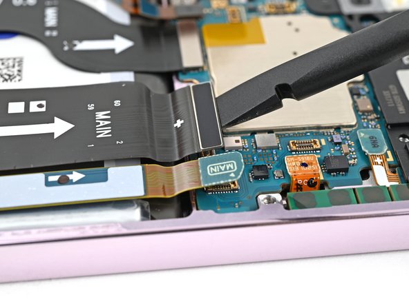
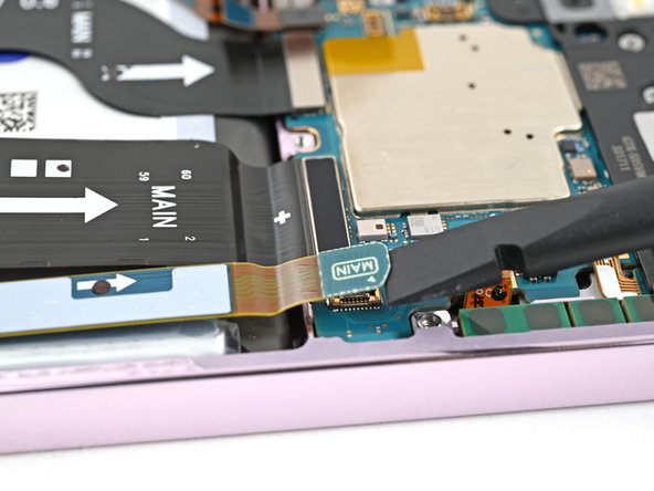
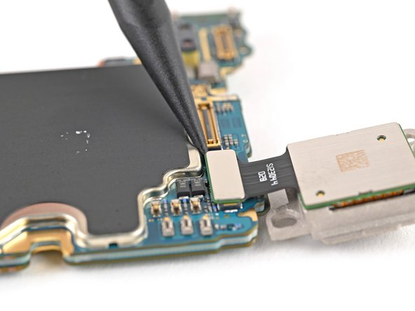
Step 29


– Alright, let’s get this party started! Use your spudger to give those display and 5G mmWave cable press connectors a little nudge and disconnect them from the motherboard. It’s like giving them a high five, but with a tool! If you need help, you can always schedule a repair.
Tools Used
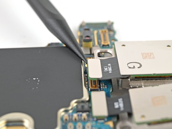
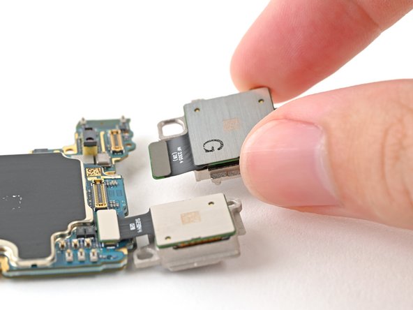
Step 30


– Now, grab your trusty spudger and give that front camera press connector a gentle nudge. It’s time to disconnect it!
Tools Used
Step 31


– Let’s get started by removing the two 3.5mm-long screws that hold the motherboard in place – simply use a Phillips screwdriver to take them out. If you need help, you can always schedule a repair
Step 32


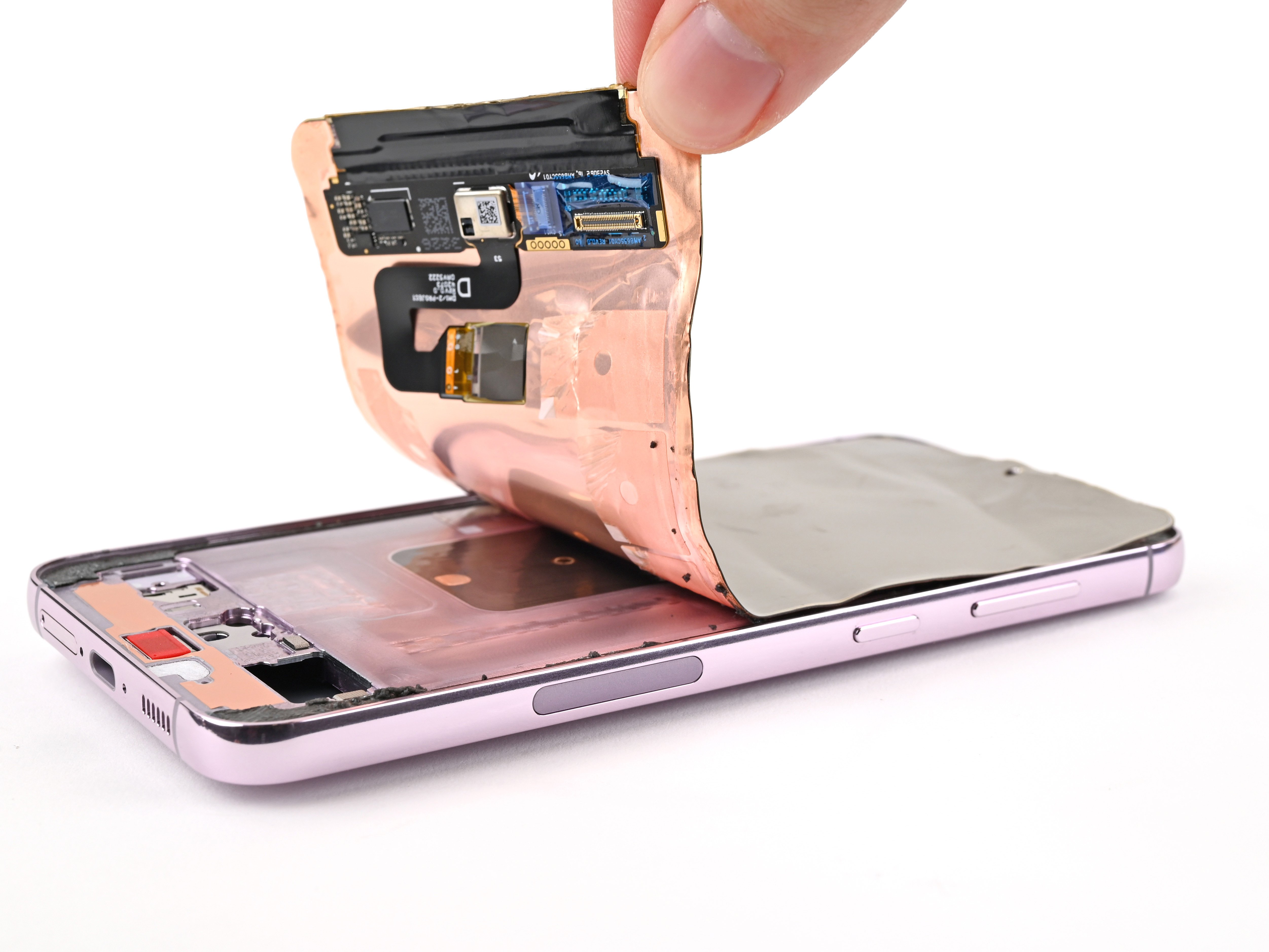
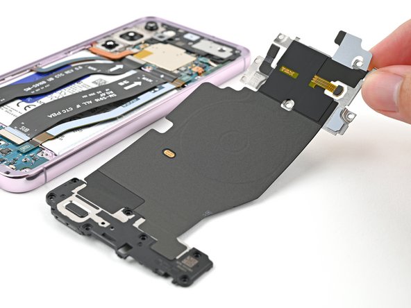
– Let’s get that motherboard out! Gently slide the flat end of your spudger between the top edge of the motherboard and the frame, right near the earpiece speaker cutout.
– Now, give that spudger a little twist to lift the motherboard up and out of the frame. Keep going until you can get a good grip on it with your fingers.
– Time to free that motherboard! Carefully remove it from the frame.
– When you’re putting everything back together, make sure all the cables are out of the way before you slide that motherboard back in. You want a smooth reunion!
Tools Used
Step 33


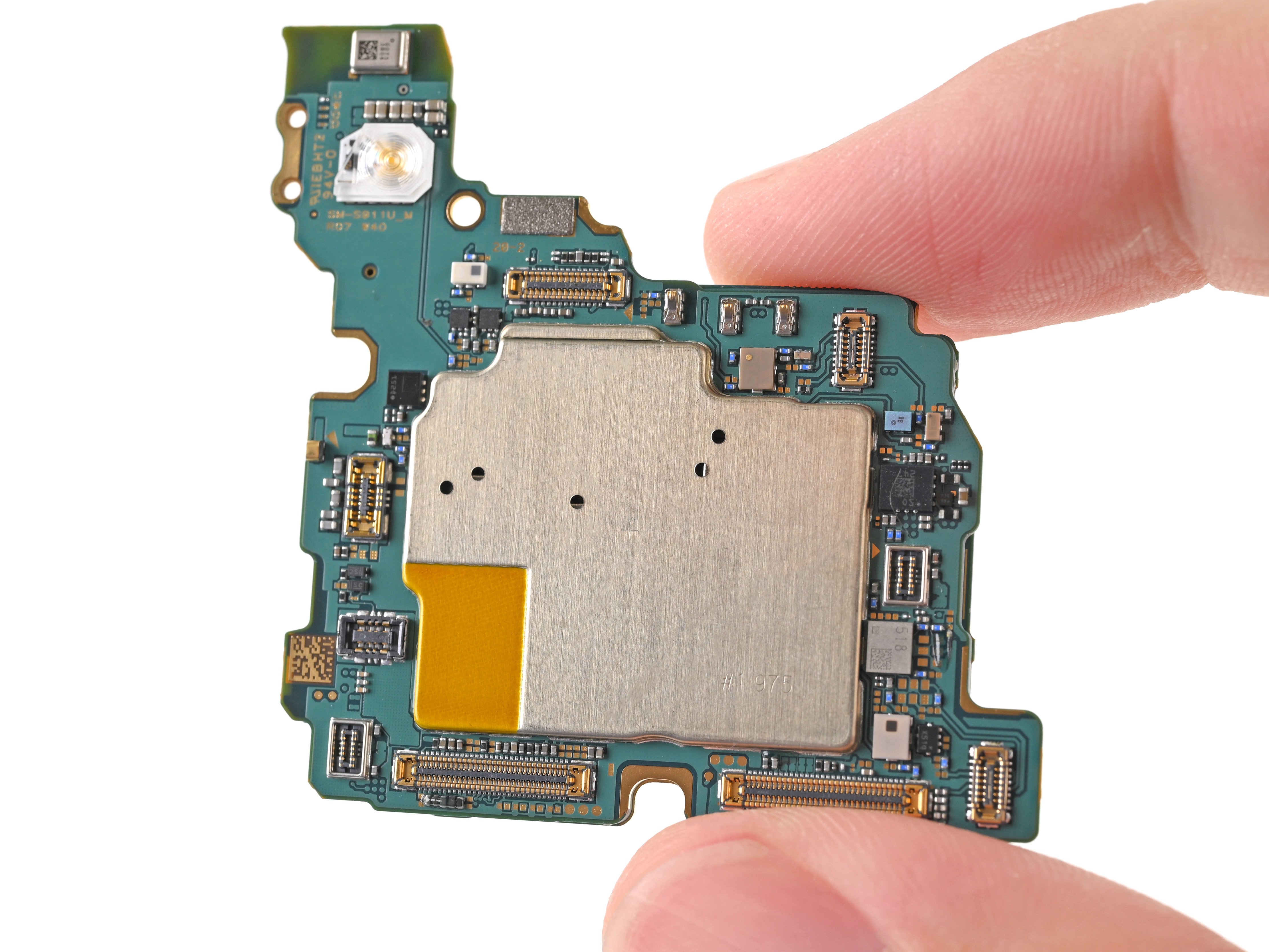
To tackle those three rear cameras, you’ll want to cleverly remove them one at a time, starting from the top and working your way down!
– Flip that motherboard over and say hello to the rear camera press connectors. They’re waiting for you!
– Now, take your trusty spudger, give that ultrawide camera press connector a little nudge, and pop it right off. Easy peasy!
Tools Used
Step 34


– The ultrawide camera is hooked into the motherboard and the main camera by metal pegs. It’s like a little party, with the camera being the guest of honor!
– While holding the motherboard, lift the ultrawide camera out of its peg holes and remove it. Don’t be shy, give it a little wiggle to get it out. You got this!
Step 35

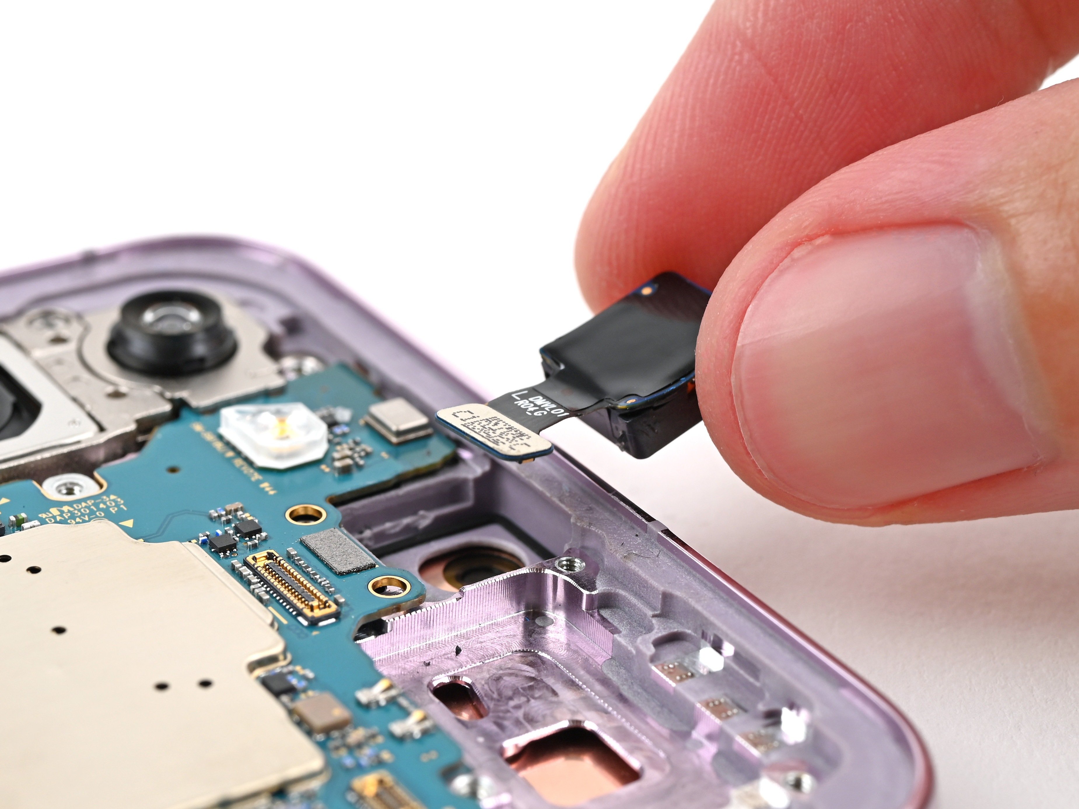
– Grab your trusty spudger and gently pry up the main camera’s press connector to disconnect it. You’ve got this!
– Now, carefully lift the main camera off the motherboard and set it aside. Easy peasy!
Tools Used
Step 36


– Time to get started – use the point of a spudger to carefully pry up and disconnect the telephoto camera press connector. Take your time and work gently to avoid any damage.
– Now it’s time to lift the telephoto camera off the motherboard and remove it. This is a great opportunity to get a closer look at the inner workings of your device.
– When you’re reassembling, don’t forget to reinstall the rear cameras in the opposite order – it’s like a little puzzle (Telephoto → Main → Ultrawide). If you need help or get stuck, you can always schedule a repair with Salvation Repair.
Tools Used