DIY Guide: Replace Samsung Galaxy Attain 4G Front Camera
Duration: 45 minutes
Steps: 15 Steps
Step 1

– Start by flipping the device over so the screen is facing down. Let’s get this party started!


Step 3


– Set the battery door aside for now, you won’t be needing it at the moment.
– Next, use a pry tool or your trusty fingernail to carefully pry the battery up and out of its compartment.
– You’ve successfully removed the battery – nice job! If you need help with the next steps or anything else, you can always schedule a repair
Step 4

– Alright, so this is gonna sound a little weird, but when you pop in that fresh battery, make sure the arrow on the bottom is pointing down. It’s like giving your device a little direction! Don’t worry, it’s easy peasy. If you get stuck, you can always schedule a repair with us, and we’ll get you back up and running in no time!
Step 5

– Time to unscrew! Grab your trusty Phillips head screwdriver and carefully take out the 6 screws holding that rear housing snug. You’re almost there!
Step 6

– Using a spudger or plastic pry tool, carefully work your way around the phone, easing it out from between the display and rear housing. Take your time and gently release the clips – you’re making great progress! If you need help, you can always schedule a repair
Tools Used

Step 7

– Time to get this repair started – gently lift the rear housing away from the display assembly.
Step 8

– Time to get started! Use your trusty spudger or plastic pry tool to carefully disconnect the headphone jack flex cable. If you need help, you can always schedule a repair
Tools Used
Step 9

– Time to get started with your repair. Using your trusty spudger or plastic pry tool, carefully disconnect the rear speaker flex cable. If you need help, you can always schedule a repair
Tools Used

Step 11

Hey there! Just a quick heads up: don’t go yanking out the logic board completely just yet, because you still need to unhook that display assembly flex cable!
– Once you’ve gracefully detached both flex cables, gently slide the logic board to the left side of the screen assembly. Keep it cool and steady!
Step 12

– Time to give that flex cable a little break! Carefully disconnect the LCD/Digitizer flex cable using your trusty spudger or plastic pry tool. You got this!
Tools Used
Step 13

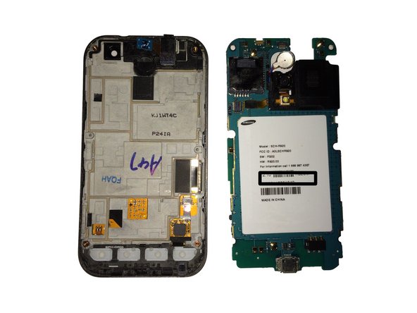
– Congratulations! You’ve successfully liberated the logic board from the display assembly. Way to go!
Step 14

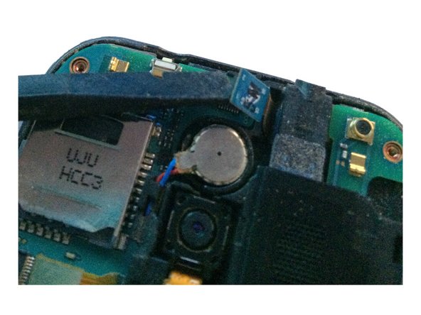
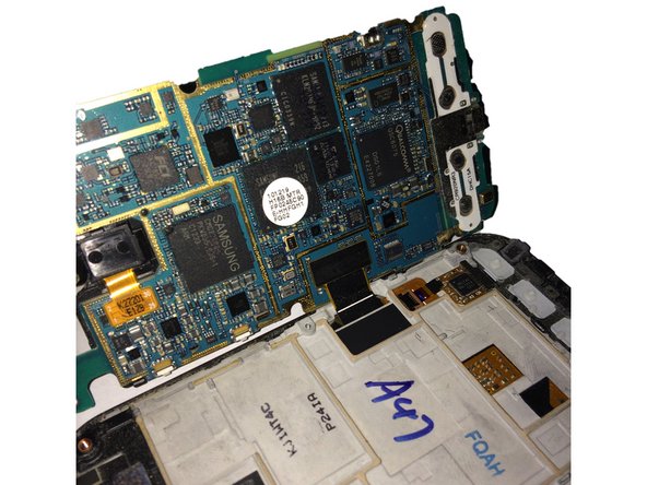
Alright, cool cat, don’t go poking at the black part, it’s kinda like a super important brain connector for the board. You know, the whole thing that makes everything work. Let’s keep those connections happy, right? If you need help, you can always schedule a repair.
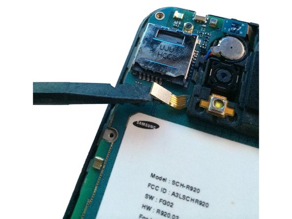
– Grab your trusty spudger or a plastic pry tool and gently lift the brown ZIF tab on the front-facing camera connector. You’ve got this!
Tools Used
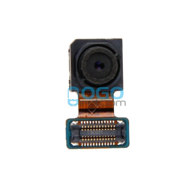
Step 15

– Alright, let’s gently coax that camera out of its cozy connector. Set it aside for now, we’ll need it later!