DIY Guide: Replace Samsung Galaxy Note10+ 5G Motherboard
Duration: 45 minutes
Steps: 24 Steps
Alright, techie! This guide’s gonna walk you through swapping out that motherboard in your Samsung Galaxy Note10+ 5G. We’re using the steps from the Note10+ guide (the one without 5G), so don’t sweat the minor differences in the pics. They won’t trip you up. Need a hand? You can always schedule a repair.
Step 1


– Grab a SIM eject tool, a bit, or even a straightened paper clip, and gently slide it into the tiny hole on the SIM card tray located at the top edge of your phone.
– Give it a firm push to pop that tray out.
– Carefully pull out the SIM card tray and set it aside.
Step 2

Make sure to power down your phone completely before diving into the disassembly process. We’ve got this!
A hair dryer, heat gun, or hot plate can be used to help loosen the adhesive, but just remember to be cool—don’t overheat the phone! The display and battery are kinda sensitive to high heat. If you need help, you can always schedule a repair.
– Get ready to unlock your device’s full potential. Start by heating up an iOpener and applying it to the left edge of the rear cover for about a minute. If you need help, you can always schedule a repair
Tools Used

Step 3


If your rear cover is lookin’ a little rough, don’t sweat it! A layer of clear packing tape might be just the trick to help the suction cup stick. Or, if you’re feeling extra strong, you can use some extra heavy-duty tape instead. And if you’re still struggling, you can always superglue the suction cup to the broken cover. It’s all good!
Hey, depending on how old your phone is, this step might be a little bit tricky. Don’t worry! If you’re having trouble, just heat up the edge a bit more and give it another go. You got this!
– Grab your trusty suction cup and stick it to the warm edge of the rear cover, getting as close to the edge as you can.
– Give that suction cup a solid, steady pull to start creating a sweet little gap between the rear cover and the frame.
– Now, slide the point of an opening pick into that gap you’ve just made.
Step 4


Be careful not to slide the opening pick in too deep—doing so might tangle with internal parts and cause a ruckus!
– Slide the opening pick along the left edge, then shimmy it towards the bottom left corner to loosen up the adhesive.
– Keep the pick in place in the bottom left corner so that adhesive doesn’t stick back together. You’re doing great!
Step 5


As you finish off the last corners of the phone, you’ll notice the rear cover starting to pop off. It’s like a little surprise party for your device!
– Let’s keep the heat going! Repeat the heating and cutting steps for the other three sides of your phone. Like a pro, leave an opening pick on each side as you move to the next to stop the adhesive from getting too cozy.
– If you need help, you can always schedule a repair.
Step 6


Remember to power up your device and give your repair a quick test drive before you go all in with the new adhesive and seal it up. You’ve got this!
– Gently lift the rear cover straight up to free it from the device.
– Ready to seal things up? Check out this guide to properly reinstall the rear cover and swap in some fresh adhesive.
– If you’re using Tesa tape for reattaching components, make sure to follow this guide for a smooth finish.
Step 7

– Alright, time to loosen up those screws holding the wireless charging coil in place! Grab your trusty Phillips screwdriver and give those five 4 mm screws a little twist to the left. You got this! If you need help, you can always schedule a repair
Step 8


– Time for a little adventure under the hood! Gently use a pair of tweezers to carefully lift and flip back the metal shield that protects the battery connector. If you need help, you can always schedule a repair!
Tools Used


Step 10


– Now it’s time to carefully disconnect the wireless charging coil connector from the motherboard – simply use the pointed end of a spudger to gently release it. If you need help, you can always schedule a repair
Tools Used
Step 11


Alright, so that wireless charging coil is stuck on there with some sticky stuff. Don’t worry, it’s not a super strong bond. We’ll get it off with a little care.
– Give that metal shield a little lift! You’ll be able to get a good grip on it with your fingers.
– Now, let’s give that wireless charging coil a gentle peel away from the device.
– You got this! Now you can remove the wireless charging coil. If you need help, you can always schedule a repair
Step 12

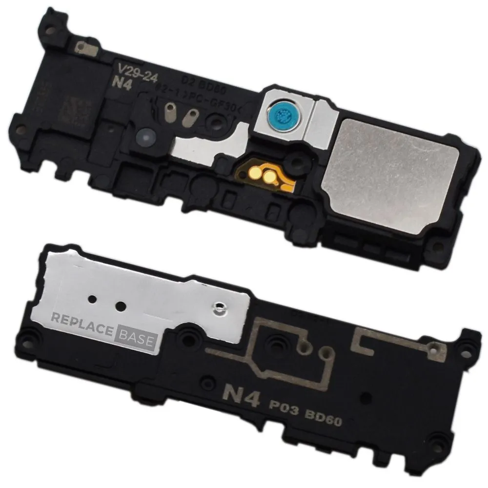
– Let’s get those speakers out! Grab your trusty Phillips screwdriver and take out the five 4 mm screws holding the loudspeaker in place. You got this! If you need help, you can always schedule a repair.


Step 14


– Grab your trusty spudger and gently use the pointed end to unplug the main interconnect cable from the motherboard. You’ve got this!
– Next up, it’s time to disconnect the secondary interconnect cable from the motherboard. Just a little tug and you’re on your way!
Tools Used


Step 16

– Let’s get started by removing the main interconnect cable. This is a crucial step, so take your time and make sure it’s done correctly. If you need help, you can always schedule a repair
Step 17


Hey there! Don’t go messing with that secondary interconnect cable. It’s connected to the side 5G mmWave antenna and if you mess with it, well, we might not be able to fix it. If you need help, you can always schedule a repair.
– Carefully pry the secondary interconnect cable away from the battery using a spudger or your fingers – don’t worry, it’s easier than it sounds. If you need help, you can always schedule a repair
Tools Used
Step 18

– Grab your trusty Phillips screwdriver and get ready to tackle those four 4 mm screws holding down the top plastic cover. You’ve got this!


Step 20


– Let’s connect! Use the tip of your trusty spudger to gently unplug the touch layer connection from the motherboard’s port. Then, let’s team up again to disconnect the side button connector from the motherboard’s home base!
Tools Used
Step 21


– Grab your trusty spudger and carefully wiggle it under the 5G mmWave antenna connector to pop it off the motherboard. Easy peasy!
– Now, with a gentle touch, bend that cable away from the motherboard like you’re giving it a little stretch.
Tools Used
Step 22


– Grab your trusty spudger and gently use its pointed end to unplug the S-Pen charging coil connector from the motherboard. You’re doing great!
Tools Used
Step 23


– Grab your trusty spudger and gently use the pointed end to unplug the display cable from the motherboard. You’ve got this!
Tools Used
Step 24


Hey, don’t forget to give your SIM tray a little tug if it seems like it’s got a case of the stuckies! Need some help? You can always schedule a repair!
– Grab your trusty spudger and gently nudge the motherboard up just enough so you can get a good grip on it with your fingers.
– Now, go ahead and lift that motherboard out!
Tools Used